M3N-65981413VDO Transmitter
Continental Automotive Systems, Inc.
Click to zoom
Application Details
- Equipment Class
- DCD - Part 15 Low Power Transmitter Below 1705 kHz
- Date of Grant
- Feb 03, 2004
- Application Purpose
- Original Equipment
- Date of Application
- Feb 03, 2004
- Equipment Note
- VDO Transmitter
- Frequency Range
- 0.12500000 - 0.12500000
- Country
- United States
Documents & Files
Document Text
Text extracted from the exhibit documents filed with the FCC. Open a document above to read the original.
Users Manual
Re: Certification for Siemens 5WY7280 Transmitter Model: 5WY7280 FCC ID: M3N-65981413 IC: 267F-65981413 USER'S MANUAL INFORMATION (PRELIMINARY) The User's Manual is in preparation. The following material will be contained in the manual: FCC ID: M3N-65981413 IC: 267F-65981413 This device complies with Part 15 of the FCC Rules and with RSS-210 of Industry Canada. Operation is subject to the following two conditions: (1) This device may not cause harmful interference, and (2) This device must accept any interference received, including interference that may cause undesired operation. WARNING: Changes or modifications not expressively approved by the party responsible for compliance could void the user's authority to operate the equipment. The term “IC:” before the radio certification number only signifies that Industry Canada technical specifications were met.
Attestation Statements
Re: Certification for Siemens 5WY7280 Transmitter Model: 5WY7280 FCC ID: M3N-65981413 IC: 267F-65981413 POWER OF ATTORNEY A letter granting Valdis V. Liepa the Power of Attorney is on file and can be provided when so requested. Re: Certification for Siemens 5WY7280 Transmitter Model: 5WY7280 FCC ID: M3N-65981413 IC: 267F-65981413 REQUEST FOR CONFIDENTIALITY Pursuant to 47 CRF 0.459, Siemens requests that a part of the subject application be held confidential. This comprises Exhibits (5) Schematics (10) Parts List (Part of Exhibit only) Siemens has spent substantial effort in developing this product and it is one of the first of its kind in industry. Having the subject information easily available to "competition" would negate the advantage they have achieved by developing this product. Not protecting the details of the design will result in financial hardship. If there are any questions regarding this request, please contact me at the above address or call 734-483-4211, fax 734-647-2106 or e-mail [email protected]. Sincerely, Valdis V. Liepa Research Scientist University of Michigan February 1, 2004 Re: Certification for Siemens 5WY7280 Transmitter Model: 5WY7280 FCC ID: M3N-65981413 IC: 267F-65981413 STATEMENT OF MODIFICATIONS There were no modifications made to the DUT by this test laboratory. (Also see Section 3.1 of the attached Test Report). _____________________ Valdis V. Liepa Research Scientist Re: Certification for Siemens 5WY7280 Transmitter Model: 5WY7280 FCC ID: M3N-65981413 IC: 267F-65981413 GENERAL PRODUCT INFORMATION The device, for which certification is pursued, has been designed by: Siemens Automotive Corporation 2400 Executive Hills Drive Auburn Hills, Michigan 48326-2980 USA Matthew Doyle Tel: 248.764.6724 Fax: 248.764.7124 It will be manufactured by: Siemens VDO S.A. de C.V. Camino a la Tijera # 3, Km 3.5 Carretera Guadalajara-Morelia C.P. 45640 Mpio. Tlajomulco de Zúñiga, Jalisco Mexico Matthew Doyle Tel: 248.764.6724 Fax: 248.764.7124 Canadian Contact: Siemens Automotive Ltd. 2775 St. Etienne Boulevard Windsor ,ON N8W 5B1 Kurt Van Drus [email protected] 1(519)974-5400 1(519)974-5401
Cover Letter(s)
February 1, 2004 American Telecommunications Certification Body, Inc. 6731 Whittier Avenue Suite C110 McLean, VA 22101 RE: Certification Application FCC ID: M3N-65981413 Please find enclosed application materials for certification of Siemens 5WY7280 Transmitter. Note: 1) portions of this submittal are filed Confidential 2) a list of the modifications made is provided in Attestations. If there are any questions regarding the application or testing performed, please contact me at the above address or call 734-483-4211, fax 734-647-2106, or e-mail [email protected]. Sincerely, Valdis V. Liepa Research Scientist
Cover Letter(s)
February 1, 2004 Federal Communications Commission Equipment Approval Services P.O. Box 358315 Pittsburgh, PA 15251-5315 Re: Certification for Siemens 5WY7280 Transmitter Model: 5WY7280 FCC ID: M3N-65981413 IC: 267F-65981413 Please find enclosed application materials for certification of Siemens 5WY7280 Transmitter. We tested it and found it to comply with FCC Part 15. If there are any questions regarding the application or testing performed, please contact me at the above address or call 734-483-4211, fax 734-647-2106, or e-mail [email protected]. Sincerely, Valdis V. Liepa Research Scientist February 1, 2004 Certification and Engineering Bureau Industry Canada 3701 Carling Avenue, Bldg. 94 Ottawa, Ontario K2H 8S2 Re: Certification for Siemens 5WY7280 Transmitter Model: 5WY7280 FCC ID: M3N-65981413 IC: 267F-65981413 Please find enclosed application materials for certification of Siemens 5WY7280 Transmitter. We tested the device and found it to comply with RSS-210. The product is identified by: IC: 267F-65981413 If there are any questions, suggestions, etc., regarding the application or testing performed, please contact me at the above address or call 734-483-4211, fax 734-647- 2106; e-mail: [email protected]. Sincerely, Valdis V. Liepa Research Scientist
Operational Description
Technical Information Siemens VDO PASE/RKE Module GM Easy Key 295 ECU General Product Information Design Location: Siemens VDO Automotive 4685 Investment Drive Troy, MI 48098 Manufactured Location: Siemens VDO S.A. de C.V. Camino a la Tijera # 3 Km 3.5 Carretera Guadalajara-Morelia C.P. 45640 Mpio. Tlajomulco de Zúñiga, Jalisco Mexico Device ID: GM Easy Key 295 ECU ID: 5WY7280 GM Easy Key Active Antenna ID: 5WY7155 General Description The Easy Key PASE system consists of a CID (Customer Identification Device), an ECU (Electronic Control Unit), 7 passive ferrite antennas, and an Active Antenna. The ECU transmits information to the CID through a 125kHz ASK carrier and the CID transmits information to the ECU through a 315MHz ASK carrier. The passive antennas are used to transmit the 125kHz. The system allows for PASE (Passive Start and Entry) and well as RKE (Remote Keyless Entry). Passive entry is initiated by lifting the door handle. The ECU will then generate a 125kHz field, which the CID will read and respond back to the ECU via 315MHz. The keypad on the CID can be used for RKE, where pushing a button transmits a command at 315MHz. Passive start is initiated by pressing the start button inside the vehicle. As with passive entry, the ECU generates a 125kHz signal and the CID responds back with a 315MHz signal. A backup for instances where RF is not possible is through limphome mode with the CID. In this case, the CID is placed near the Active Antenna (certified under different FCC/IC grant application). The ECU sends a command to the Active Antenna to generate a 125kHz field. The CID will respond back by dampening the field through absorption modulation. Power Supply The ECU is powered by the vehicle battery. Typical Usage Pattern 110 PASE operations in 24 hours with a total transmission length of 5.5 seconds Transmitter ON 0.23 seconds/hour Transmitter OFF 3599.77 seconds/hour Duty Cycle: T ON / T (ON+OFF) X100% = 0.23/3599.77X100% = 0.006% Immobilizer Protection The immobilizer section of the ECU is powered by a regulated 5-volt supply. This supply has an absolute maximum current capability of 500mA, with a typical maximum capability of 200mA. The supply can operate up to 45V maximum and has a thermal shut-off should the power dissipation exceed the device’s limits. Therefore the immobilizer is limited to a 5V supply with a maximum of 500mA (200mA typical maximum). The immobilizer IC performs antenna diagnostics each time the antenna is activated. These diagnostics check for an open or shorted antenna. The ECU will shut down the antenna driver should a continuous open or short exist.
Test Report
The University of Michigan Radiation Laboratory 3228 EECS Building Ann Arbor, MI 48109-2122 Tel: (734) 764-0500 Measured Radio Frequency Emissions From Siemens Transmitter Model: 5WY7280 Report No. 415031-187 February 1, 2004 Copyright © 2004 For: Siemens VDO 2400 Executive Hills Drive Auburn Hills, MI 48326-2980 Contact: Kevin Cotton Tel: (248) 764-6771 Fax: (248) 764-7171 Tests supervised by: Measurements made by: Valdis V. Liepa Report approved by: _____________________ Valdis V. Liepa Research Scientist Summary Tests for compliance with FCC Regulations, Part 15, Subpart C, and for compliance with Industry Canada RSS-210, were performed on Siemens VDO transmitter, model 5WY7280. This device is subject to Rules and Regulations as a transmitter. In testing completed October 27, 2003, the device tested in the worst case met the allowed specifications for transmitter radiated emissions by 7.9 dB (see p. 7); digital emissions, Class B, were met by at least 20 dB. The conducted emissions tests do not apply, since the device is powered from a 12 VDC system. 2 1. Introduction Siemens model 5WY7280 was tested for compliance with FCC Regulations, Part 15, adopted under Docket 87-389, April 18, 1989, and with Industry Canada RSS-210, Issue 5, November, 2001. The tests were performed at the University of Michigan Radiation Laboratory Willow Run Test Range following the procedures described in ANSI C63.4-1992 "Methods of Measurement of Radio-Noise Emissions from Low-Voltage Electrical and Electronic Equipment in the Range of 9 kHz to 40 GHz". The Site description and attenuation characteristics of the Open Site facility are on file with FCC Laboratory, Columbia, Maryland (FCC Reg. No: 91050) and with Industry Canada, Ottawa, ON (File Ref. No: IC 2057). 2. Test Procedures and Equipment Used The pertinent test equipment commonly used in our facility for measurements is listed in Table 2.1 below. The middle column identifies the specific equipment used in these tests. Table 2.1 Test Equipment. Test Instrument Eqpt. Used Manufacturer/Model Spectrum Analyzer (0.1-1500 MHz) Hewlett-Packard, 182T/8558B Spectrum Analyzer (9kHz-22GHz) X Hewlett-Packard 8593A SN: 3107A01358 Spectrum Analyzer (9kHz-26GHz) X Hewlett-Packard 8593E, SN: 3412A01131 Spectrum Analyzer (9kHz-26GHz) Hewlett-Packard 8563E, SN: 3310A01174 Spectrum Analyzer (9kHz-40GHz) Hewlett-Packard 8564E, SN: 3745A01031 Power Meter Hewlett-Packard, 432A Power Meter Anritsu, ML4803A/MP Harmonic Mixer (26-40 GHz) Hewlett-Packard 11970A, SN: 3003A08327 Harmonic Mixer (40-60 GHz) Hewlett-Packard 11970U, SN: 2332A00500 Harmonic Mixer (75-110 GHz) Hewlett-Packard 11970W, SN: 2521A00179 Harmonic Mixer (140-220 GHz) Pacific Millimeter Prod., GMA, SN: 26 S-Band Std. Gain Horn S/A, Model SGH-2.6 C-Band Std. Gain Horn University of Michigan, NRL design XN-Band Std. Gain Horn University of Michigan, NRL design X-Band Std. Gain Horn S/A, Model 12-8.2 X-band horn (8.2- 12.4 GHz) Narda 640 X-band horn (8.2- 12.4 GHz) Scientific Atlanta , 12-8.2, SN: 730 K-band horn (18-26.5 GHz) FXR, Inc., K638KF Ka-band horn (26.5-40 GHz) FXR, Inc., U638A U-band horn (40-60 GHz) Custom Microwave, HO19 W-band horn(75-110 GHz) Custom Microwave, HO10 G-band horn (140-220 GHz) Custom Microwave, HO5R Bicone Antenna (30-250 MHz) X University of Michigan, RLBC-1 Bicone Antenna (200-1000 MHz) X University of Michigan, RLBC-2 Dipole Antenna Set (30-1000 MHz) X University of Michigan, RLDP-1,-2,-3 Dipole Antenna Set (30-1000 MHz) EMCO 2131C, SN: 992 Active Rod Antenna (30 Hz-50 MHz) EMCO 3301B, SN: 3223 Active Loop Antenna (30 Hz-50 MHz) X EMCO 6502, SN:2855 Ridge-horn Antenna (300-5000 MHz) X University of Michigan Amplifier (5-1000 MHz) X Avantek, A11-1, A25-1S Amplifier (5-4500 MHz) X Avantek Amplifier (4.5-13 GHz) Avantek, AFT-12665 Amplifier (6-16 GHz) Trek Amplifier (16-26 GHz) Avantek LISN Box University of Michigan Signal Generator Hewlett-Packard 8657B 3 3. Configurations and Identification of Device Under Test The DUT is a 125 kHz LF transmitter designed for an onboard automobile RFID system, and as such, it is powered from an automotive 12 VDC source. It is housed in a plastic case approximately 4 by 5 by 1.5 inches. The coils are external. For testing, a generic harness was provided by the manufacturer. The DUT was designed and manufactured by Siemens VDO, 2400 Executive Hills Drive, Auburn Hills, MI 48326-2980. It is identified as: Siemens VDO Transmitter Model: 5WY7280 FCC ID: M3N-65981413 CANADA: 267F-65981413 3.1 EMI Relevant Modifications No EMI Relevant Modifications were performed by this test laboratory. 4. Emission Limits 4.1 Radiated Emission Limits The DUT tested falls under the category of an Intentional Radiators and the Digital Devices, subject to Subpart C, Section 15.209; and Subpart B, Section 15.109 (transmitter generated signals excluded); and Subpart A, Section 15.33. The applicable testing frequencies with corresponding emission limits are given in Tables 4.1 and 4.2 below. As a digital device, it is exempt. Table 4.1. Radiated Emission Limits (FCC: 15.205, 15.35; IC: RSS-210 (6.2.2(r), 6.3)). (Transmitter) Frequency (MHz) Fundamental and Spurious* (μV/m) 0.009-0.490 0.490-1.705 2400/F(kHz), 300m 24,000/F(kHz), 30m 0.090-0.110 0.49-0.51 Restricted Bands * Harmonics must be below the fundamental. For extrapolation to other distances, see Section 6.6. 4 Table 4.2. Radiated Emission Limits (FCC: 15.33, 15.35, 15.109; IC: RSS-210, 6.2.2(r)). (Digital Class B) Freq. (MHz) E lim (3m) μV/m E lim dB(μV/m) 30-88 100 40.0 88-216 150 43.5 216-960 200 46.0 960-2000 500 54.0 Note: Average readings apply above 1000 MHz (1 MHz BW) Quasi-Peak readings apply to 1000 MHz (120 kHz BW) 4.2 Conductive Emission Limits Table 4.3 Conducted Emission Limits (FCC:15.107 (CISPR); IC: RSS-210, 6.6). Frequency Class A (dBμV) Class B (dBμV) MHz Quasi-peak Average Quasi-peak Average .150 - 0.50 79 66 66 - 56* 56 - 46* 0.50 - 5 73 60 56 46 5 - 30 73 60 60 50 Notes: 1. The lower limit shal…
Text truncated - open the document above for the full version.
Contact Information
Applicant
Mark Kenney
Technical Contact
University of Michigan/EECSValdis V Liepa
[email protected]734-483-4211
1301 Beal Avenue · Ann Arbor, Michigan · United States
Test Firm
University of MichiganValdis Liepa
Technical Specifications
| # | Rule Parts | Frequency Range | Power Output |
|---|---|---|---|
| 1 | 15C | 0.125 MHz - 0.125 MHz | - |
Other Applications from Continental Automotive Systems, Inc.
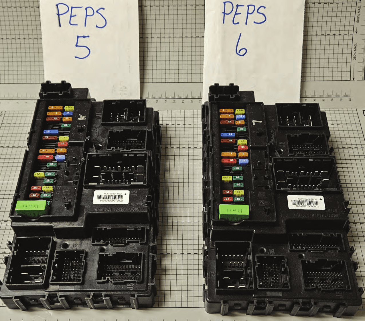
M3NA2C786860
Dec 03, 2023LF Transmitter
Equipment Class
DCD - Part 15 Low Power Transmitter Below 1705 kHz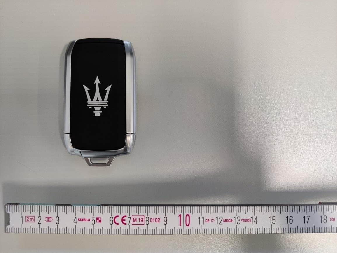
M3NRHT433
Jul 04, 2022KeyFob
Equipment Class
DSC - Part 15 Security/Remote Control Transmitter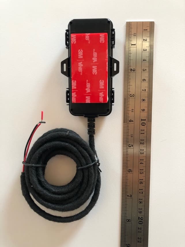
M3NRCKF2B
Apr 25, 2021RCKF2B
Equipment Class
DSC - Part 15 Security/Remote Control Transmitter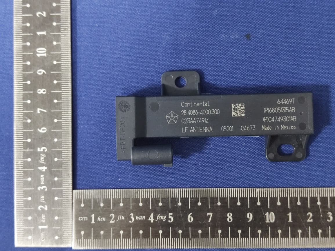
M3NWXRFHM1
Jan 28, 2021FCA WL/WS PASE System MY 2021
Equipment Class
DCD - Part 15 Low Power Transmitter Below 1705 kHz
M3NMAS433
Jan 20, 2021Car Key
Equipment Class
DSR - Part 15 Remote Control/Security Device Transceiver