M3N-IMMOBILISER2TSentry Key Immobilizer System
Continental Automotive Systems, Inc.
Click to zoom
Application Details
- Equipment Class
- DCD - Part 15 Low Power Transmitter Below 1705 kHz
- Date of Grant
- Feb 23, 2000
- Application Purpose
- Original Equipment
- Date of Application
- Feb 08, 2000
- Equipment Note
- Sentry Key Immobilizer System
- Frequency Range
- 0.13400000 - 0.13400000
- Country
- United States
Documents & Files
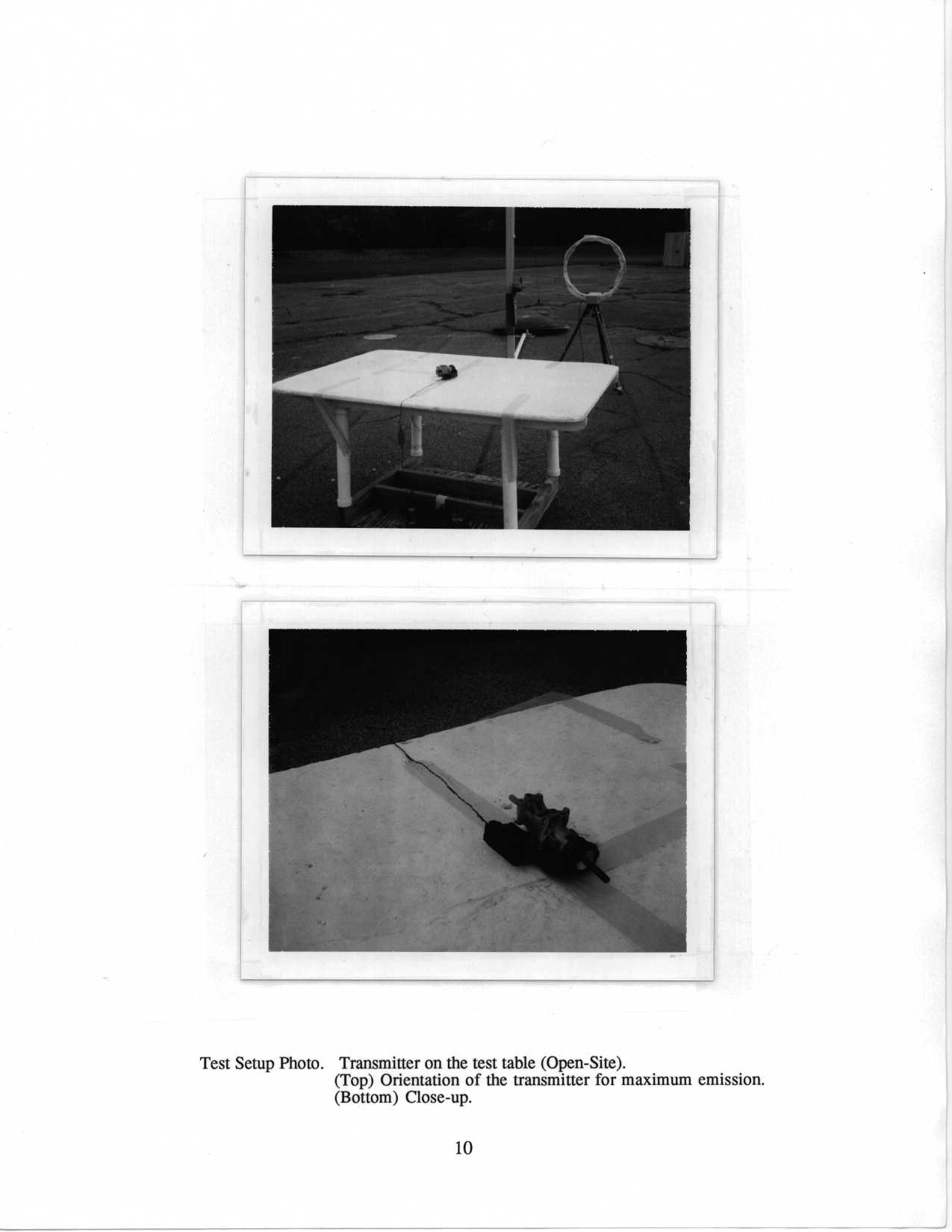
Document Text
Text extracted from the exhibit documents filed with the FCC. Open a document above to read the original.
Block Diagram
DaimlerChrysler SKIM Internal Block Diagram Ignition Battery J1850 Bus Ground Antenna X1-6 X1-1 X1-2 X1-5 X1-3 X1-4 X2-1 RF ASIC SKIM Data RF Rx RF Tx Digital Tx/Rx Filter DriverX2-2 Microprocessor Power Supply & I/O Logic Control Status Serial Bus, Control, & Status Bus Interface Transponder Magnetic Field EXHIBIT 04 Page 1 0f 1 U of Mich file 415031 – 013
Operational Description
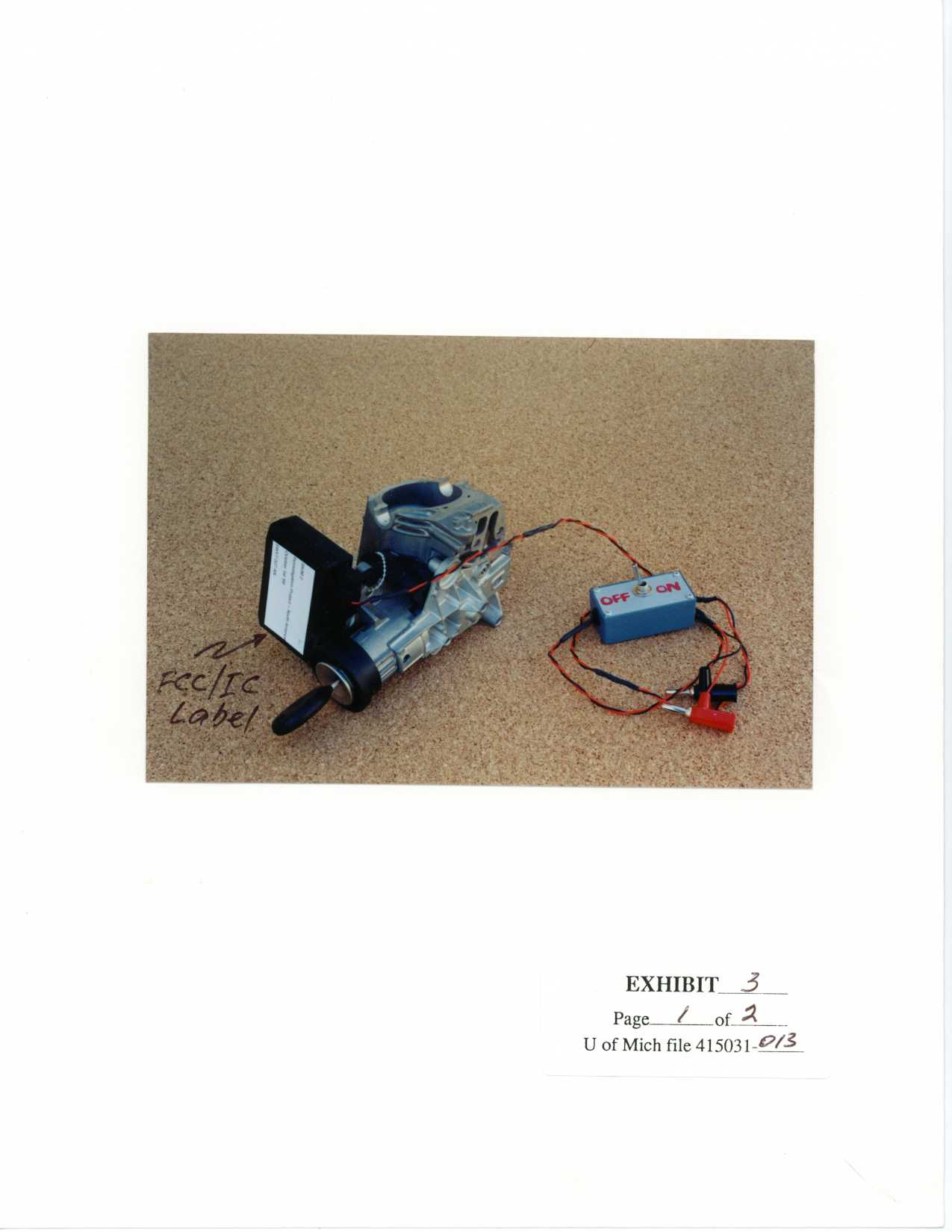
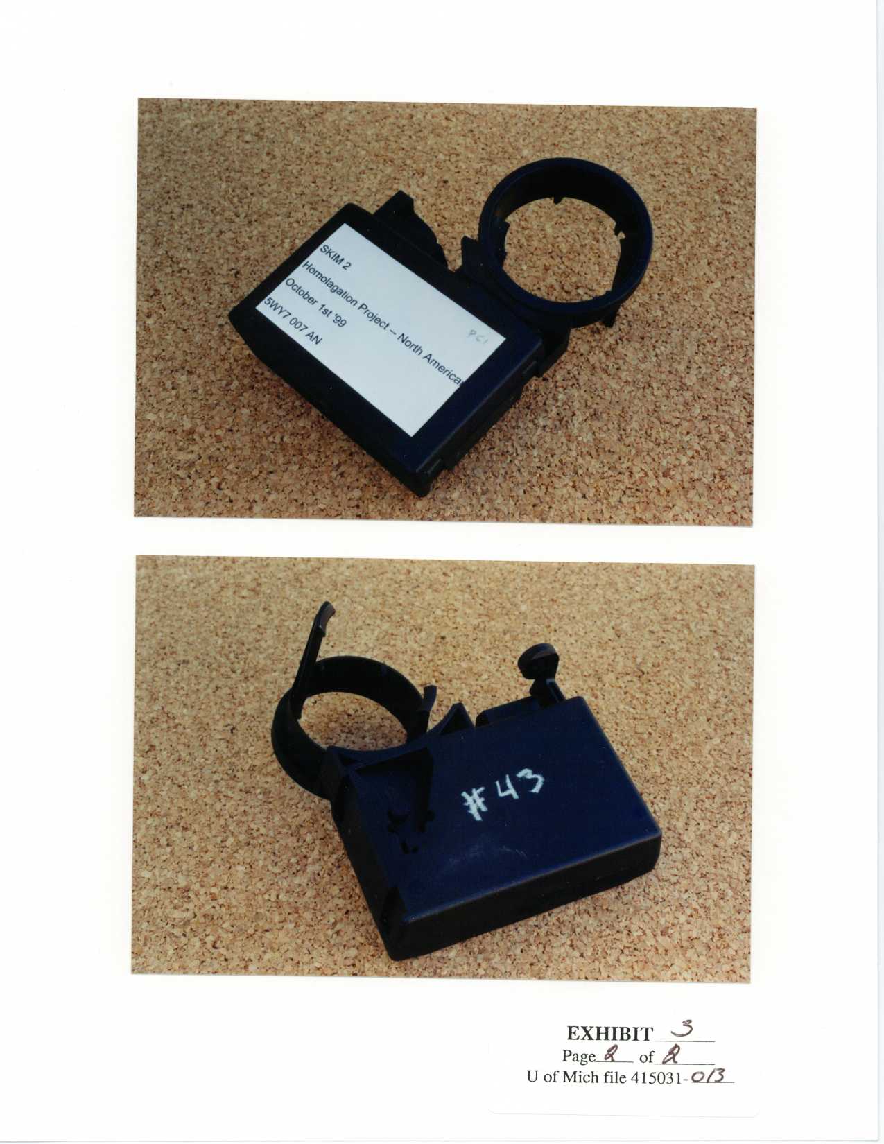
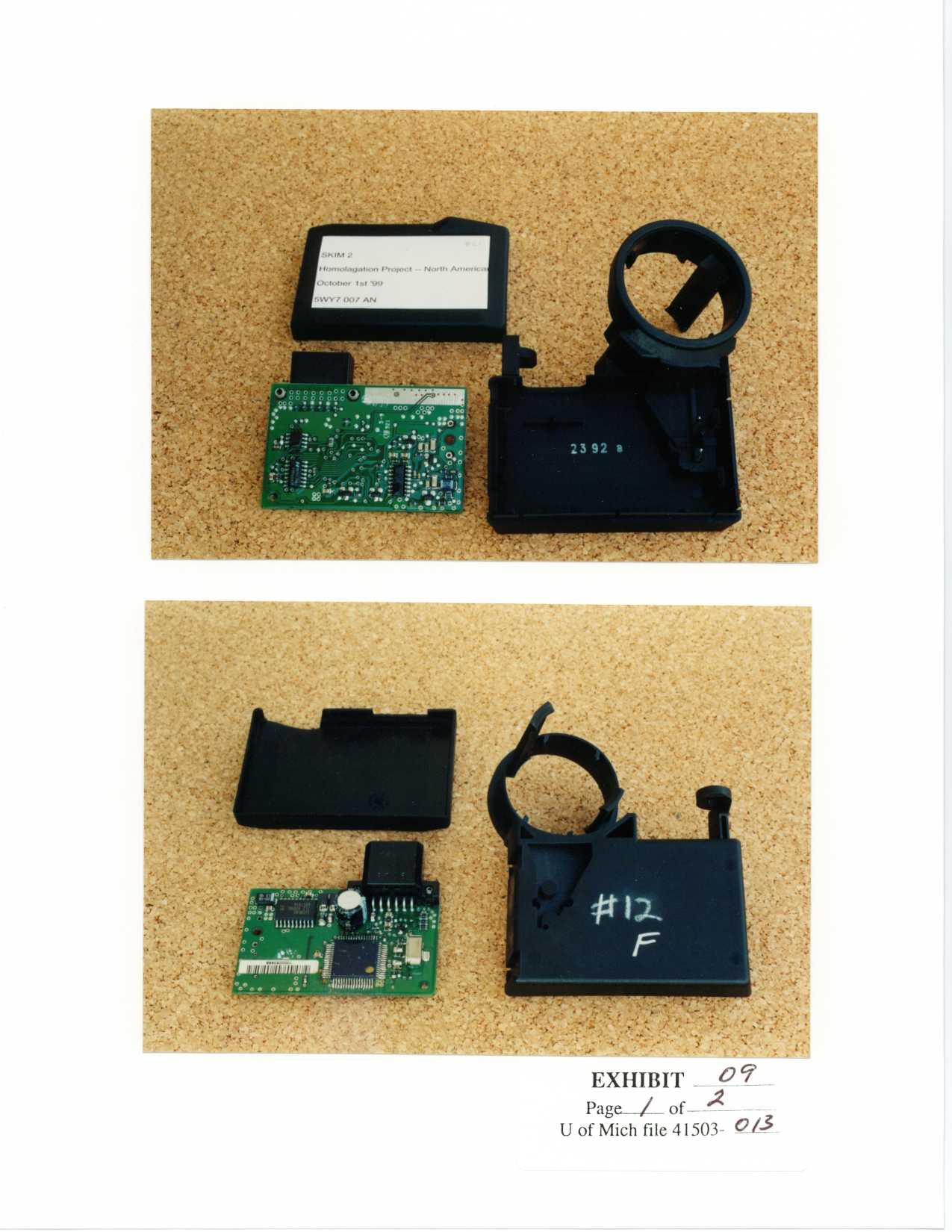
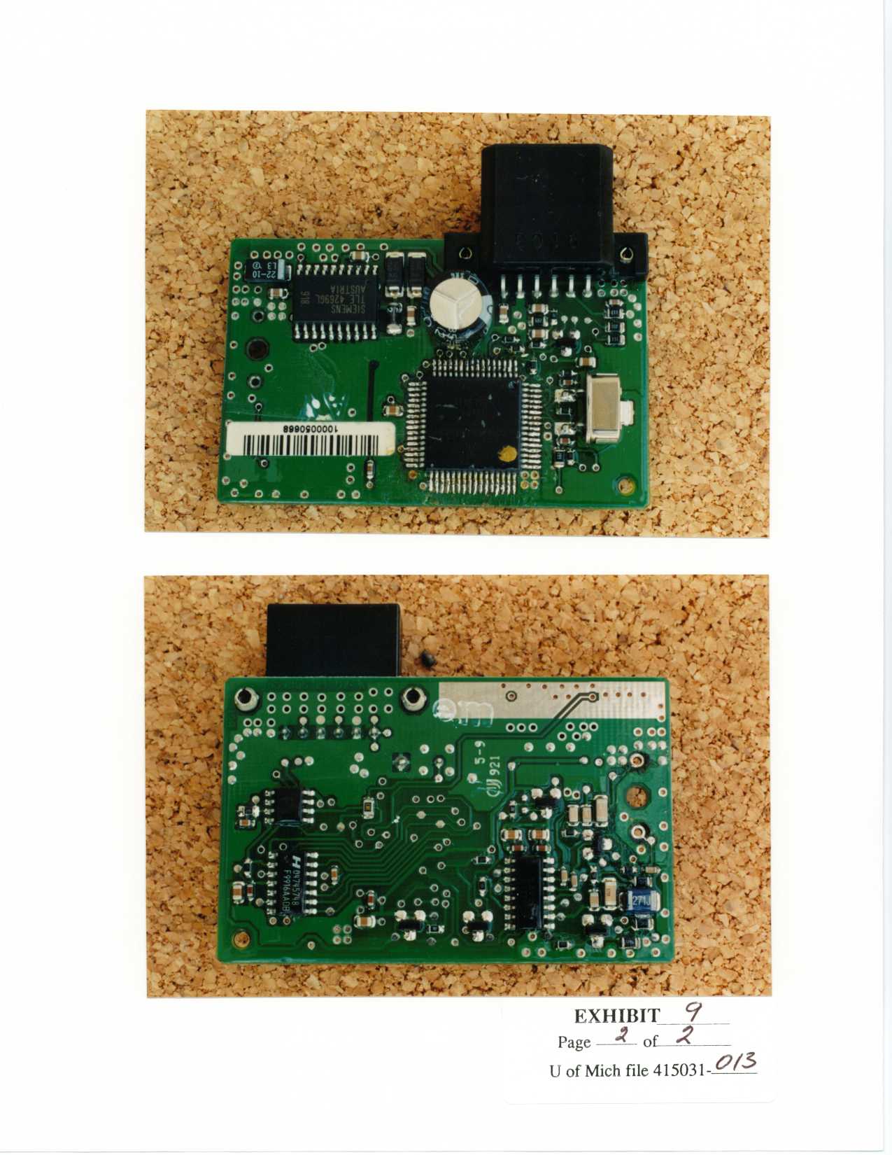
FUNCTIONAL DESCRIPTION OF THE DaimlerChrysler SKIM 2 System Components The DaimlerChrysler SKIS (Sentry Key Immobilizer System) is a vehicle immobilization system. The electronic devices in the SKIS are the SKIM 2 and a Cryptographic Transponder. The SKIM 2 is located near the vehicle’s ignition lock. The Transponder is located within the ignition key. The Transponder is magnetically coupled to the SKIM 2. The Control Module is connected via a wire harness to vehicle power, vehicle ground, vehicle ignition, and a J1850 vehicle communications bus. The J1850 communications bus is a single line 0V to 7.5V wave-shape controlled interface. This bus allows communications between the SKIM 2 and other vehicle controllers such as the Engine Management System and Body Controller. System Operation The SKIS is a passive immobilization system. The SKIM 2 uses a magnetic couple to read the Transponder’s identification code. The SKIM 2 compares the identification code received from the Transponder with identification codes stored in its non-volatile memory. If the identification code from the Transponder matches one of the identification codes stored in memory, the SKIM 2 sends a “Valid Key” message to the Engine Management System controller. If there is no match, the SKIM 2 sends an “Invalid Key” message to the Engine Management System controller. This causes the Engine Management System to turn off the engine. The SKIM 2 remains in a low-power “sleep” mode while vehicle ignition is off. When vehicle ignition is turned on, the SKIM 2 wakes up, runs some internal diagnostics, and then attempts to communicate with the Transponder. Once the results of the Transponder communications have been sent to the Engine Management System, the SKIM 2 goes into an idle mode. Twice per second it will send a status message on the vehicle communications bus. It will also respond to commands and message sent by other modules on the communications bus. The SKIM 2 remains in this mode until ignition is turned off. The SKIM 2 will perform some internal clean-up operations, delay for several seconds, and then go into the low-power “sleep” mode. The SKIM 2 will attempt to communicate with the Transponder eight times. Once successful communications have occurred the SKIM 2 stops communicating with the Transponder. Each attempt consists of the following steps: 1. Charge mode, 2. Transmit mode, 3. Receive mode, 4. Delay for internal processing. EXHIBIT 12 Page 1 0f 2 U of Mich file 415031 - 013 Charge Mode The charge mode provides an initial surge of power to the Transponder. The Transponder wakes up, performs an internal reset sequence, then waits for a command from the SKIM 2. Charge mode is similar to transmit mode. However, rather than modulated data only one long burst of oscillation occurs. Total charge time is 50mS. Transmit Mode In transmit mode, a pair of drivers is used to drive a series resonant circuit. When resonating, the circuit generates a 134.2kHz magnetic field which is coupled with the Transponder in the nearby key. Transmit data modulates the magnetic field by turning the drivers on or off. Data consists of commands to the Transponder. Total transmit time varies from 4mS to 100mS. Receive Mode A few milliseconds after the SKIM 2 stops transmitting energy to the Transponder, the Transponder starts sending data back to the Control Module. The Transponder sends Frequency Shift Keyed (FSK) encoded binary data at 130kHz to 139.5kHz for a low bit and 118kHz to 128kHz for a high bit. The SKIM 2's antenna is magnetically coupled with the Transponder. The SKIM 2's series resonant circuit is excited by the Transponder’s signal. The data received in the resonant circuit is amplified. Then the SKIM 2's logic uses a digital sampling technique to decode and demodulate the data. Data consists of responses to the commands sent in transmit mode. Total response time is always under 25mS. EXHIBIT 12 Page 2 0f 2 U of Mich file 415031 - 013
Contact Information
Applicant
Mark Kenney
Technical Contact
University of Michigan/EECSValdis V Liepa
[email protected]734-483-4211
1301 Beal Avenue · Ann Arbor, Michigan · United States
Non-Technical Contact
University of Michigan/EECSValdis V Liepa
[email protected]734-483-4211
Test Firm
University of MichiganValdis Liepa
Technical Specifications
| # | Rule Parts | Frequency Range | Power Output |
|---|---|---|---|
| 1 | 15C | 0.134 MHz - 0.134 MHz | - |
Other Applications from Continental Automotive Systems, Inc.
M3NA2C786860
Dec 03, 2023LF Transmitter
Equipment Class
DCD - Part 15 Low Power Transmitter Below 1705 kHz
M3NRHT433
Jul 04, 2022KeyFob
Equipment Class
DSC - Part 15 Security/Remote Control Transmitter
M3NRCKF2B
Apr 25, 2021RCKF2B
Equipment Class
DSC - Part 15 Security/Remote Control Transmitter
M3NWXRFHM1
Jan 28, 2021FCA WL/WS PASE System MY 2021
Equipment Class
DCD - Part 15 Low Power Transmitter Below 1705 kHz
M3NMAS433
Jan 20, 2021Car Key
Equipment Class
DSR - Part 15 Remote Control/Security Device Transceiver