M3N-IPATSU152Integrated Passive Anti-Theft System
Continental Automotive Systems, Inc.
Click to zoom
Application Details
- Equipment Class
- DCD - Part 15 Low Power Transmitter Below 1705 kHz
- Date of Grant
- Mar 22, 2000
- Application Purpose
- Original Equipment
- Date of Application
- Mar 12, 2000
- Equipment Note
- Integrated Passive Anti-Theft System
- Frequency Range
- 0.13500000 - 0.13500000
- Country
- United States
Documents & Files
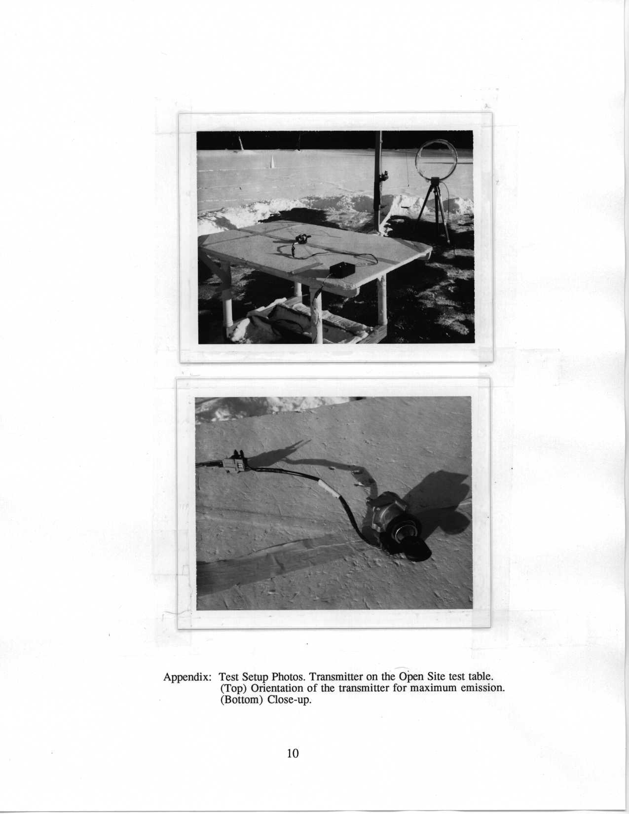
Document Text
Text extracted from the exhibit documents filed with the FCC. Open a document above to read the original.
Block Diagram
SIEMENS SIEMENSAUTOMOTIVE AT BE AS Copyright © by SIEMENS Automotive CorpMarch 1, 2000 All rights reserved. SIEMENS Confidential Last printed 03-03-00 12:37 PM System Block Diagram Powertrain Control Module Vehicle Battery +- ATIC Power Supply Antenna TX_CNTL RX-Out Ground Ground Transceiver Module Transponder Transceiver antenna coil
ID Label/Location Info
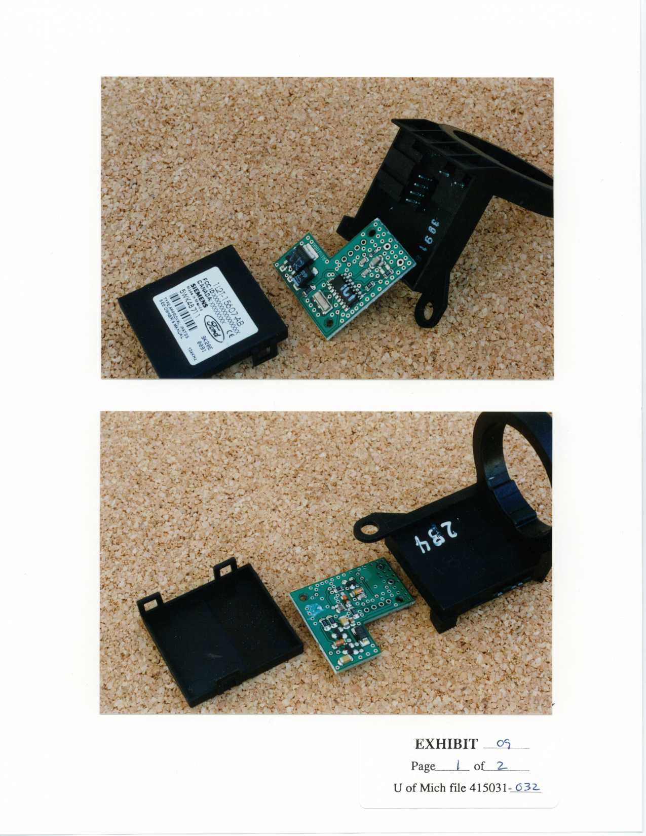
SIEMENS SIEMENSAUTOMOTIVE AT BE AS Copyright © by SIEMENS Automotive CorpMarch 1, 2000 All rights reserved. SIEMENS Confidential Last printed 03-03-00 12:37 PM Label Drawing Bar CodeDate CodeSerial Number Label Location Label is placed here Mechanical Drawing of the U152 IPATS Transceiver
Operational Description
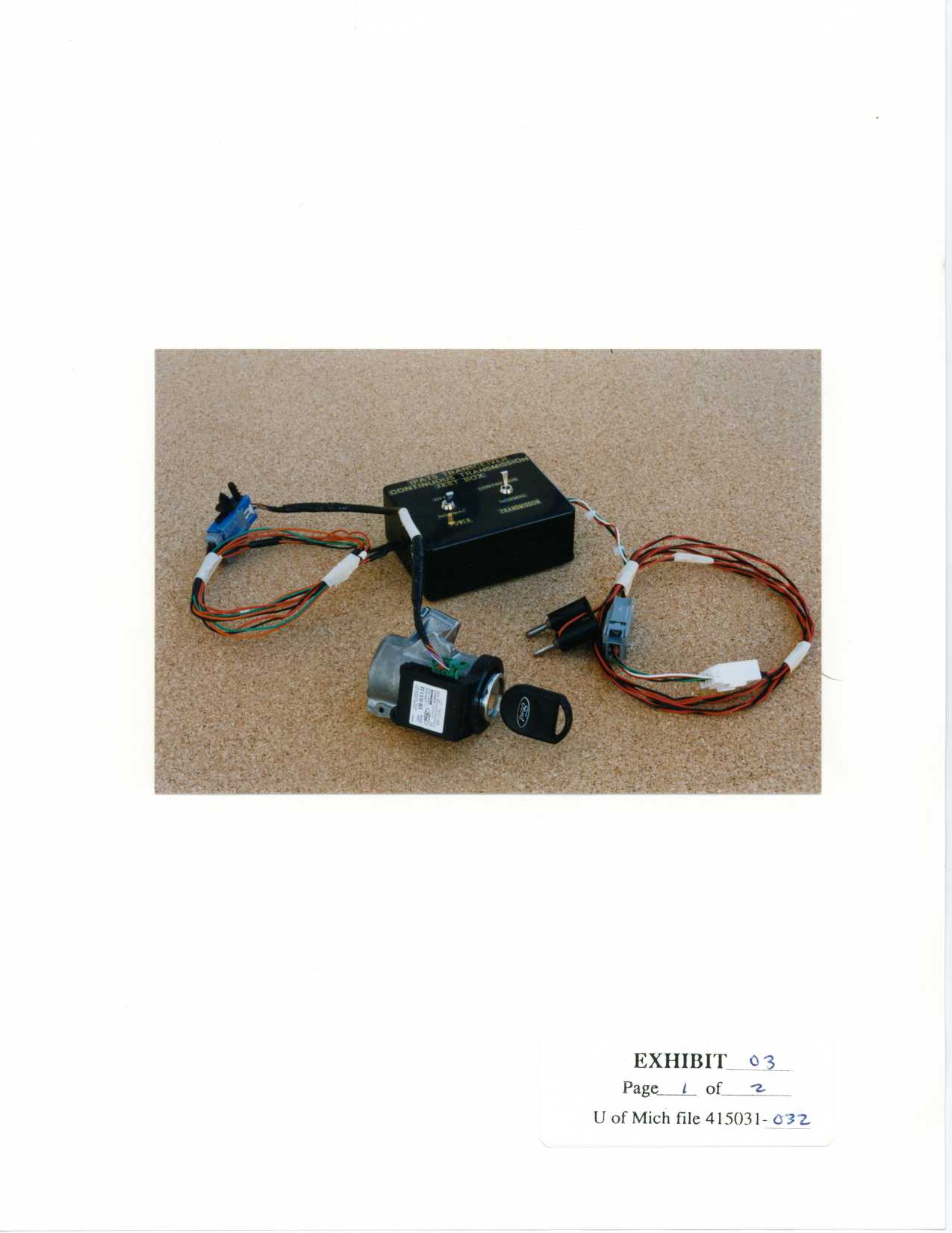
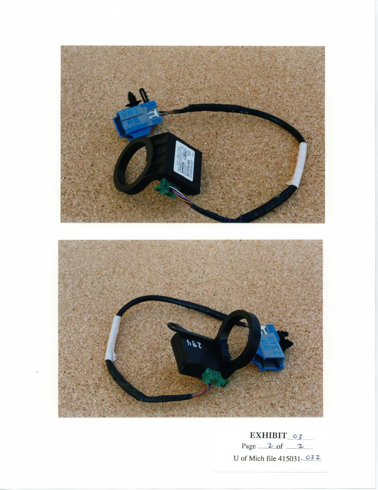
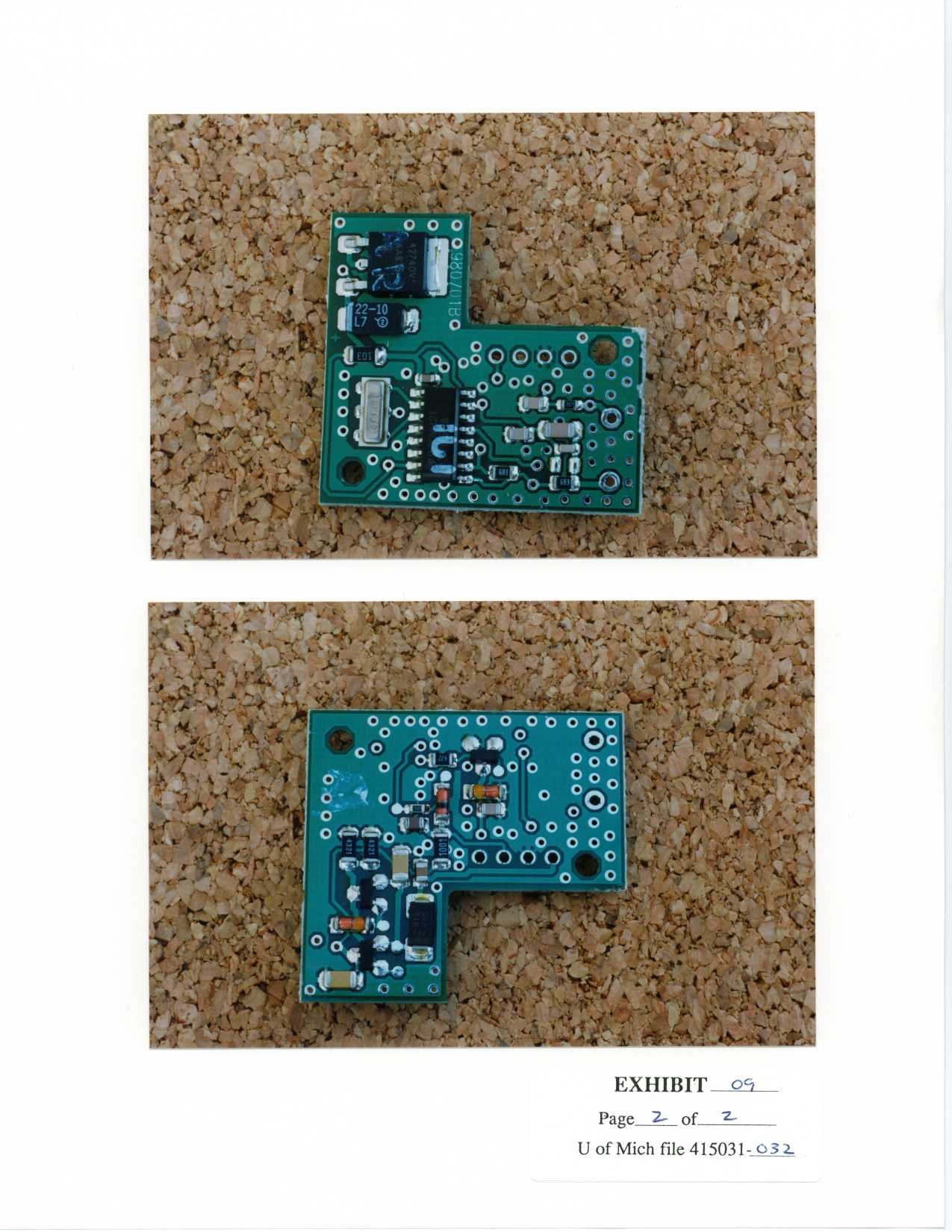
SIEMENS SIEMENSAUTOMOTIVE AT BE AS Copyright © by SIEMENS Automotive CorpMarch 1, 2000 All rights reserved. SIEMENS Confidential Last printed 03-03-00 12:37 PM Functional Description of the U152 Transceiver The IPATS (Integrated Passive Anti-Theft Systems) Transceiver is a component within the immobilizer subsystem for Ford vehicles. The purpose of the subsystem is to prevent drive away vehicle theft by disabling the vehicle if an unauthorized user attempts to start the vehicle. The other components of the immobolizer subsystem are the Transponder/Key assembly, the Powertrain Control Module and the indicator LED. The Transceiver modulates signals sent by the Powertrain module and demodulates and decodes signals sent by the Transponder/Key. Theory of Operation The IPATS transceiver is controlled by, and communicates directly with, the PCM (Powertrain Control Module). When ignition (Run/Start) switch is turned on, the ignition voltage is sensed by the PCM. The transmit control (TX_CNTL) input is then asserted low by the PCM, starting the charge phase. The charge phase and write phase are both controllable via the transmit control input. At the leading edge of the transmit control signal the mode control byte is written, and the transmit control signal remains low for the duration of the charge phase which will energize the transponder in the ignition key. During the charge phase, the IPATS transceiver will send a status byte to the PCM on the Rx (SCI-Out) output. After the charge phase, the PCM transmits a 48 bit cryptographic seed to the transceiver on the Transmit Control line. The transceiver modulates this data to communicate with the transponder, located in the ignition key, using the XCVR antenna as a magnetically coupled LF interface. The Transceiver modulates the PWM data into PWM-ASK (100% AM) bursts of nominally 134.2 kHz radiation. Subsequently the transponder will compute and transmit a unique code to the transceiver, based on the seed and its unique ID. The transmission protocol is Frequency Shift Keying (FSK). A Data Zero is generated from 16 cycles of 134.2 kHz and a Data One is generated from 16 cycles of 123.2 kHz. The code will be demodulated, and sent to the PCM in SCI (NRZ) format from the Rx output of the transceiver. Upon writing to the PCM, the process will be complete, and the transceiver will enter a sleep mode until the next ignition cycle.
Contact Information
Applicant
Mark Kenney
Technical Contact
University of Michigan/EECSValdis V Liepa
[email protected]734-483-4211
1301 Beal Avenue · Ann Arbor, Michigan · United States
Non-Technical Contact
University of Michigan/EECSValdis V Liepa
[email protected]734-483-4211
Technical Specifications
| # | Rule Parts | Frequency Range | Power Output |
|---|---|---|---|
| 1 | 15C | 0.135 MHz - 0.135 MHz | - |
Other Applications from Continental Automotive Systems, Inc.
M3NA2C786860
Dec 03, 2023LF Transmitter
Equipment Class
DCD - Part 15 Low Power Transmitter Below 1705 kHz
M3NRHT433
Jul 04, 2022KeyFob
Equipment Class
DSC - Part 15 Security/Remote Control Transmitter
M3NRCKF2B
Apr 25, 2021RCKF2B
Equipment Class
DSC - Part 15 Security/Remote Control Transmitter
M3NWXRFHM1
Jan 28, 2021FCA WL/WS PASE System MY 2021
Equipment Class
DCD - Part 15 Low Power Transmitter Below 1705 kHz
M3NMAS433
Jan 20, 2021Car Key
Equipment Class
DSR - Part 15 Remote Control/Security Device Transceiver