M3N5WY7130Automotive Receiver
Continental Automotive Systems, Inc.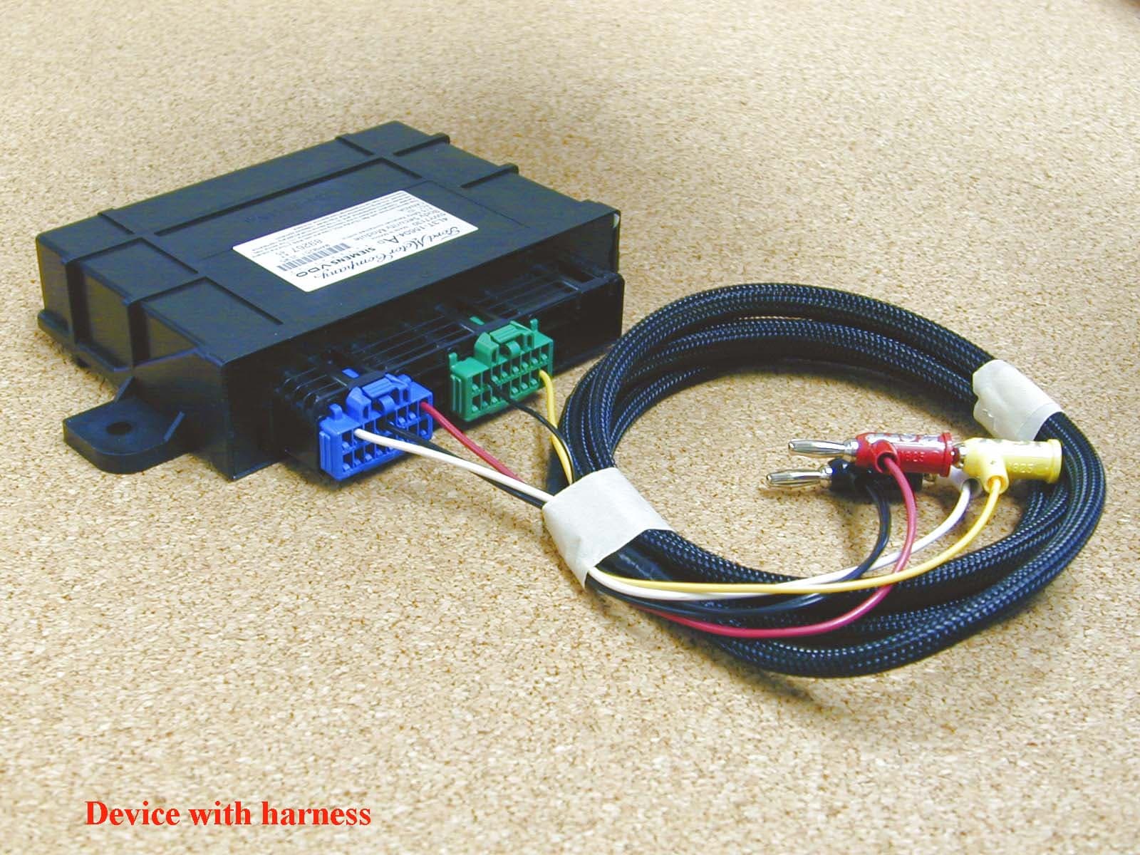
Click to zoom
Application Details
- Equipment Class
- CRR - Superregenerative Receiver
- Date of Grant
- Jan 23, 2003
- Application Purpose
- Original Equipment
- Date of Application
- Jan 23, 2003
- Equipment Note
- Automotive Receiver
- Frequency Range
- 315.00000000 - 315.00000000
- Country
- United States
Documents & Files
Document Text
Text extracted from the exhibit documents filed with the FCC. Open a document above to read the original.
Users Manual
Re: Certification for Siemens P221 BSM Receiver Model: P221 BSM 5WY7130 FCC ID: M3N5WY7130 IC: 267F-5WY7130 USER'S MANUAL INFORMATION (PRELIMINARY) The User's Manual is in preparation. The following material will be contained in the manual: FCC ID: M3N5WY7130 IC: 267F-5WY7130 This device complies with Part 15 of the FCC Rules and with RSS-210 of Industry Canada. Operation is subject to the following two conditions: (1) This device may not cause harmful interference, and (2) This device must accept any interference received, including interference that may cause undesired operation. WARNING: Changes or modifications not expressively approved by the party responsible for compliance could void the user's authority to operate the equipment. The term “IC:” before the radio certification number only signifies that Industry Canada technical specifications were met.
Block Diagram
Receiver Block Diagram The receiver has the following sections: Antenna Match/Filter, Low Noise Amplifier, SuperRegenerative Detector, Baseband Amplifier, and Data Slicer. The following Receiver Block Diagram shows the relationship between these sections. Low Noise Amplifier 10 - 15 dB Gain @ 315 MHz@-30dBm Super- Regenerative Detector Antenna Match/ Filter PCB Antenna & Matching Components Z 315 MHz Oscillator 315 MHz Band Pass Filter 315 MHz High/Band Pass Filter & Impedance Match 1 MHz Quench 315 MHz ASK 200 KHz Low Pass Filter Amp/LPF 50 dB Gain/ Fc @ 10 KHz 500 KHz to 2 MHz FSK Baseband Manchester Data encoded @ 2 KHz Radiated RF Input Baseband Amplifier 2ms Avg. Ref. w/ 30 mV Offset & 10 mV Signal Hysterisis Data Slicer BLOCK DIAGRAM BSM-Module Block Diagram: ST72321R6 uC RF Receiver Darlington Driver Discrete Driver Digital Inputs: - XX_Ajar_SW_IN - Jet_Ajar_SW_IN - Trim_Unlock_SW_IN - Trim_Lock_SW_IN - Keypad_X_SW_IN - IGN_Run_Start_IN - Autolamp_SW_IN - Reset_SW_IN Analog Inputs: - Autolamp_Sensor_IN - BATT - Horn_LSD_OUT - PWR_GND - Signal_GND - Keypad_GND - Headlamp_PWR UPLIC (communication) Outputs: - Horn_LSD_OUT Outputs: - All_Lock_RLY_OUT - All_Unlock_RLY_OUT - DF_Unlock_RLY_OUT - Keypad_ILL_OUT Headlamp_RLY_OUT Parklamp_RLY_OUT Scan A EEPROM Voltage Regulator Autolamp Sensor DOL_SENSC ST72321R6 uC RF Receiver Darlington Driver Discrete Driver Digital Inputs: - XX_Ajar_SW_IN - Jet_Ajar_SW_IN - Trim_Unlock_SW_IN - Trim_Lock_SW_IN - Keypad_X_SW_IN - IGN_Run_Start_IN - Autolamp_SW_IN - Reset_SW_IN Analog Inputs: - Autolamp_Sensor_IN - BATT - Horn_LSD_OUT - PWR_GND - Signal_GND - Keypad_GND - Headlamp_PWR UPLIC (communication) Outputs: - Horn_LSD_OUT Outputs: - All_Lock_RLY_OUT - All_Unlock_RLY_OUT - DF_Unlock_RLY_OUT - Keypad_ILL_OUT Headlamp_RLY_OUT Parklamp_RLY_OUT Scan A EEPROM Voltage Regulator Autolamp Sensor DOL_SENSC
Cover Letter(s)
Re: Certification for Siemens P221 BSM Receiver Model: P221 BSM 5WY7130 FCC ID: M3N5WY7130 IC: 267F-5WY7130 POWER OF ATTORNEY A letter granting Valdis V. Liepa the Power of Attorney is on file and can be provided when so requested. Re: Certification for Siemens P221 BSM Receiver Model: P221 BSM 5WY7130 FCC ID: M3N5WY7130 IC: 267F-5WY7130 REQUEST FOR CONFIDENTIALITY Pursuant to 47 CRF 0.459, Siemens requests that a part of the subject application be held confidential. This comprises Exhibits (5) Schematics (10) Parts List (Part of Exhibit only) Siemens has spent substantial effort in developing this product and it is one of the first of its kind in industry. Having the subject information easily available to "competition" would negate the advantage they have achieved by developing this product. Not protecting the details of the design will result in financial hardship. If there are any questions regarding this request, please contact me at the above address or call 734-483-4211, fax 734-647-2106 or e-mail [email protected]. Sincerely, Valdis V. Liepa Research Scientist University of Michigan January 17, 2003 Re: Certification for Siemens P221 BSM Receiver Model: P221 BSM 5WY7130 FCC ID: M3N5WY7130 IC: 267F-5WY7130 STATEMENT OF MODIFICATIONS There were no modifications made to the DUT by this test laboratory. (Also see Section 3.1 of the attached Test Report). _____________________ Valdis V. Liepa Research Scientist Re: Certification for Siemens P221 BSM Receiver Model: P221 BSM 5WY7130 FCC ID: M3N5WY7130 IC: 267F-5WY7130 GENERAL PRODUCT INFORMATION The device, for which certification is pursued, has been designed by: Siemens VDO Automotive 267F-5WY7130 4685 Investment Drive Troy, MI 48098 Joe Laforges Tel: 248 764-6739 Fax: 248-764-7139 [email protected] It will be manufactured by: Siemens VDO S.A. de C.V. Camino a la Tijera # 3, Km 3.5 Carretera Guadalajara-Morelia C.P. 45640 Mpio. Tlajomulco de Zúñiga, Jalisco Mexico Joe Laforges Tel: 248 764-6739 Fax: 248-764-7139 [email protected]
Cover Letter(s)
RE: Siemens VDO Automotive FCC ID: MEN5WY7130 Response to Reviewers questions: 1) The EUT was tested to < 1 GHz, but the test equipment list in the report does not show what antenna was used > 1 GHz. The Ridge-horn antenna (300-5000MHz) was used for f>1 GHz. We missed putting an 'X' in Table 2.1. 2) From the internal photographs, it appears that the antenna trace may extend to the external connector. However, additional cabling external to the unit does not appear to have been used during testing. Please provide rational for not testing with an external connection. This receiver will not use and external antenna. There will not be a connection made to the interface pin where the PCB antenna trace terminates. To avoid a possible, but improbable, violation of the Authorization, we propose that a restriction on the Grant be stated, such as "for use with internal PCB antenna only". 3) Please note that when measurements above 1 GHz are made, that both peak and average measurements should normally be provided, unless the peak measurements meet the average limit. Please comment on the peak to average ratio seen for this device. We measured all peak values of emissions. In the test report, Section 5, we justify the reason for applicability of PK measurement to QP and AVE limits. In our case, the PK measurements met the average limits, hence the AVE measurement was not made. For receivers such as here, emissions, if any, are noise-like and for such the PK- to-AVE ratio is typically 12 dB (measured 12.9 dB at 1.4 GHz for noise).
ID Label/Location Info
Siemens VDO Automotive Zoran Kovac Receiver Certification Information (Quote No:020718dc) 1. ID LABEL Notes: 1. MLFB Number 2. Serial Number Barcode (size: 3.5mm x 20mm): this is the BSM’s random serial number, which is linked to each module assembly components including (1) the transmitters barcode number / tic code information and (2) the Keypad ID Code Number. 3. Serial Number (human readable form) . Date Code 4. Last two digits of each transmitter‘s tic code. 5. Keypad ID Code Number, from the Keypad ID Code Card IC: 267F - 5WY7130 M3N5WY7130 C 3. 2.1. 5. 4.
Operational Description
Siemens VDO Automotive Zoran Kovac Receiver Certification Information (Quote No:020718dc) DESCRIPTION OF OPERATION 7.1. System Components: The BSM-Module is a body security module for the P221 MY 2003.75. It will be produced in North America. The BSM module arbitrates the central locking and unlocking of the vehicle doors, RKE functionality, panic alarm, courtesy lighting, and illuminated entry. A RF receiver board of Super Regenerative type is used on this module. The BS-Module has a Radio Frequency (RF) link for remote vehicle access. The receiver is a component within the RF link. The purpose of the RF link is to provide remote vehicle access. The other component of the RF link is the transmitter. The purpose of the receiver is to demodulate the RF signals from the transmitter and condition the signals for processing by the microcontroller on the Security Module 7.2 System Operation: The Siemens security control system consists of a 315 MHz transmitter and a Security module. The Security Module contains the receiver. The transmitter sends a command corresponding to the button, which is pressed. The binary command is scrambled, Manchester encoded at 2 KHz and then Amplitude Shift Keyed (ASK) modulated at 315 MHz. This 315 MHz signal is broadcast to the vehicle. The antenna on the Security Module picks up the broadcasted signal and sends it to the receiver. The receiver demodulates the signal and sends the Manchester data at TTL levels to the microcontroller. The receiver is of Super Regenerative type. The receiver does not decode the signals. The microcontroller on the Security Module decodes the signal, deciphers the command, and activates the appropriate outputs. A block diagram of the Security Module is included in this document. The module board supplies power to the receiver, regulated to 5.0 Vdc with a maximum tolerance voltage of 5.1Vdc. The receiver will not operate above 5.1Vdc. The receiver is made with a double- sided circuit board with components on one side and a continuous, unbroken ground plane on the other side.
Test Report
10 DUT on OATS Close-up on the DUT on OATS
Test Setup Photos
10 DUT on OATS Close-up on the DUT on OATS
Contact Information
Applicant
Mark Kenney
Technical Contact
University of Michigan/EECSValdis V Liepa
[email protected]734-483-4211
1301 Beal Ave. · Ann Arbor, Michigan · United States
Non-Technical Contact
University of Michigan/EECSValdis V Liepa
[email protected]734-483-4211
Test Firm
University of MichiganValdis Liepa
Technical Specifications
| # | Rule Parts | Frequency Range | Power Output |
|---|---|---|---|
| 1 | 15B | 315 MHz - 315 MHz | - |
Other Applications from Continental Automotive Systems, Inc.
M3NA2C786860
Dec 03, 2023LF Transmitter
Equipment Class
DCD - Part 15 Low Power Transmitter Below 1705 kHz
M3NRHT433
Jul 04, 2022KeyFob
Equipment Class
DSC - Part 15 Security/Remote Control Transmitter
M3NRCKF2B
Apr 25, 2021RCKF2B
Equipment Class
DSC - Part 15 Security/Remote Control Transmitter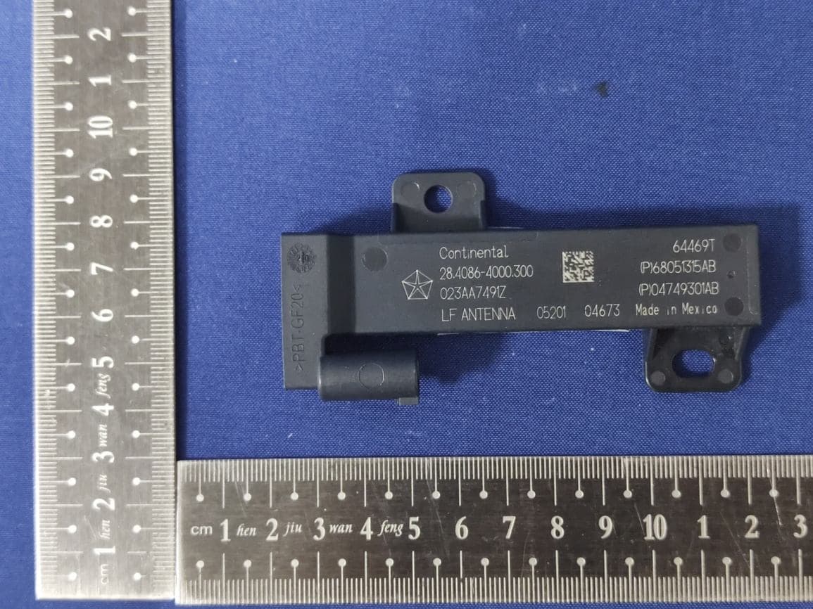
M3NWXRFHM1
Jan 28, 2021FCA WL/WS PASE System MY 2021
Equipment Class
DCD - Part 15 Low Power Transmitter Below 1705 kHz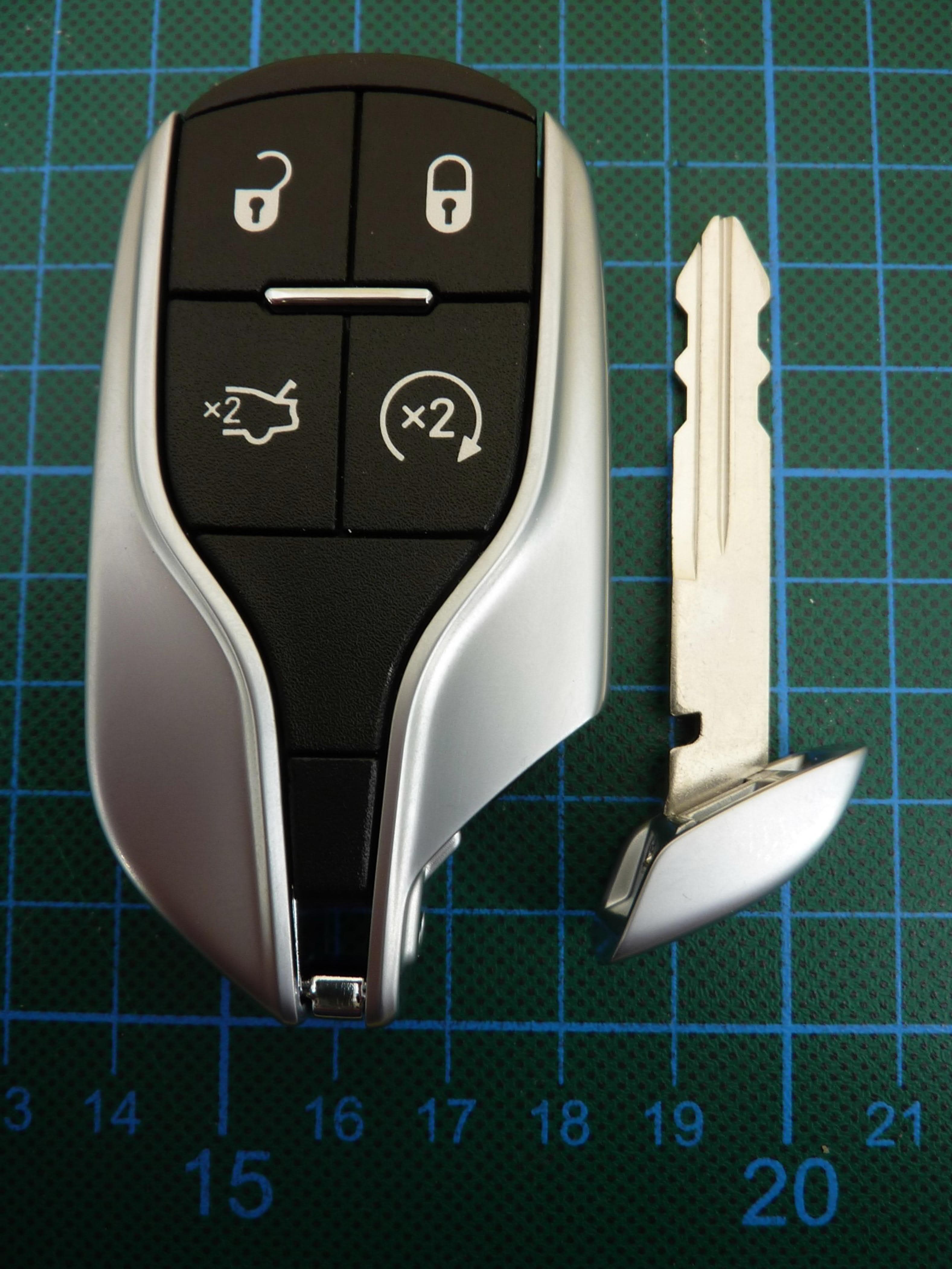
M3NMAS433
Jan 20, 2021Car Key
Equipment Class
DSR - Part 15 Remote Control/Security Device Transceiver