M3N5WY8111Auto Security/Entry Transmitter
Continental Automotive Systems, Inc.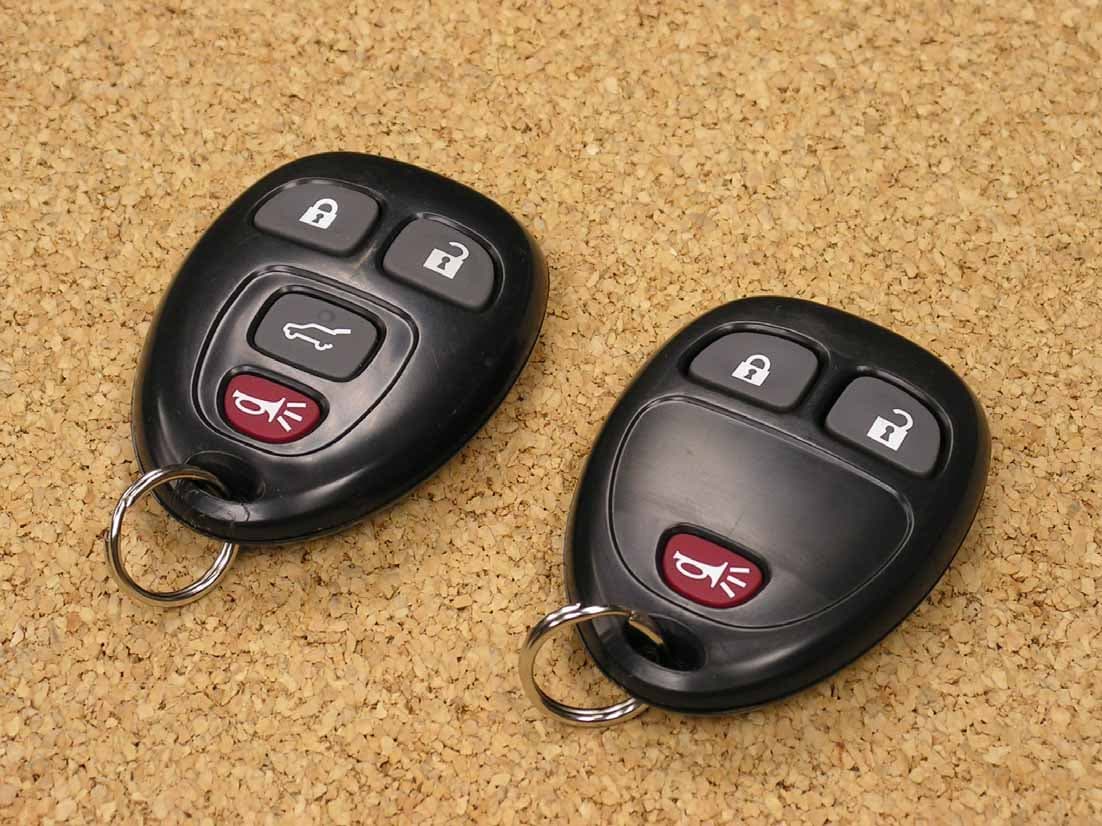
Click to zoom
Application Details
- Equipment Class
- DSC - Part 15 Security/Remote Control Transmitter
- Date of Grant
- Apr 02, 2008
- Application Purpose
- Original Equipment
- Date of Application
- Apr 02, 2008
- Equipment Note
- Auto Security/Entry Transmitter
- Frequency Range
- 315.00000000 - 315.00000000
- Country
- United States
Documents & Files
Document Text
Text extracted from the exhibit documents filed with the FCC. Open a document above to read the original.
Users Manual
Re: Certification for Siemens/Continental Transmitter Model/PN(s): 25836192, 25836194, FCC ID: M3N5WY8111 IC: 267F-5WY8111 The device under test is manufactured by the grantee (Siemens/Continental) and sold as an OEM product. Per 47 CFR 2.909, 2.927, 2.931, 2.1033, 15.15(b) etc..., the grantee must ensure the end-user has all applicable / appropriate operating instructions. When end-user instructions are required, as in the case of this product, the grantee must notify the OEM to notify the end-user. Siemens/Continental will supply the following information to the reseller/distributor dictating what must be included in the end user’s manual for the commercial product. INFORMATION TO BE INCLUDED IN THE END USER'S MANUAL The following information must be included in the end product user’s manual to ensure continued FCC and Industry Canada regulatory compliance. The ID numbers must be included in the manual if the device label is not readily accessible to the end user. The compliance paragraphs below must be included in the user's manual. ************************************************************************ FCC ID:M3N5WY8111 IC: 267F-5WY8111 This device complies with Part 15 of the FCC Rules and with RSS-210 of Industry Canada. Operation is subject to the following two conditions: (1) This device may not cause harmful interference, and (2) This device must accept any interference received, including interference that may cause undesired operation. WARNING: Changes or modifications not expressively approved by the party responsible for compliance could void the user's authority to operate the equipment. The term “IC:” before the radio certification number only signifies that Industry Canada technical specifications were met. ************************************************************************
Attestation Statements
March 25, 2008 Re: Certification for Siemens/Continental Transmitter Model/PN(s): 25836192, 25836194, FCC ID: M3N5WY8111 IC: 267F-5WY8111 STATEMENT OF MODIFICATIONS There were no modifications made to the DUT by this test laboratory. (Also see Section 3.1 of the attached Test Report). _____________________ Valdis V. Liepa Research Scientist Re: Certification for Siemens/Continental Transmitter Model/PN(s): 25836192, 25836194, FCC ID: M3N5WY8111 IC: 267F-5WY8111 GENERAL PRODUCT INFORMATION The device, for which certification is pursued, has been designed by: Siemens VDO Automotive / Continental 4685 Investment Drive Troy, MI 48098 Contact: Charles Muma [email protected] Tel: (248) 764-6771 Fax: (248) 764-7247 It will be manufactured by: Continental Automotive Guadalajara Mexico S.A. de C.V. Camino a la Tijera #3 Km 3.5 Carretera Guadalajara-Morelia Tlajomulco de Zuniga, Jalisco 45645 Mexico Contact: Charles Muma [email protected] Tel: (248) 764-6771 Fax: (248) 764-7247 Canadian Contact: Siemens Automotive Ltd. 2775 St. Etienne Boulevard Windsor ,ON N8W 5B1 Contact: Kurt Van Drus [email protected] Tel: (519) 974-5400 Fax:(519) 974-5401 Re: Certification for Siemens/Continental Transmitter Model/PN(s): 25836192, 25836194, FCC ID: M3N5WY8111 IC: 267F-5WY8111 POWER OF ATTORNEY A letter granting Valdis V. Liepa the Power of Attorney is on file and can be provided when so requested.
Block Diagram
315 MHz
Cover Letter(s)
March 25, 2008 Federal Communications Commission Equipment Approval Services P.O. Box 358315 Pittsburgh, PA 15251-5315 Re: Certification for Siemens/Continental Transmitter Model/PN(s): 25836192, 25836194, FCC ID: M3N5WY8111 IC: 267F-5WY8111 Please find enclosed application materials for certification of Siemens/Continental Transmitter. We tested it and found it to comply with FCC Part 15. If there are any questions regarding the application or testing performed, please contact me at the above address or call 734-483-4211, fax 734-647-2106, or e-mail [email protected]. Sincerely, Valdis V. Liepa Research Scientist March 25, 2008 Certification and Engineering Bureau Industry Canada 3701 Carling Avenue, Bldg. 94 Ottawa, Ontario K2H 8S2 Re: Certification for Siemens Transmitter Model/PN(s): 25836192, 25836194, FCC ID: M3N5WY8111 IC: 267F-5WY8111 Please find enclosed application materials for certification of Siemens Transmitter. We tested the device and found it to comply with RSS-GEN/102/210. The product is identified by: IC: 267F-5WY8111 If there are any questions, suggestions, etc., regarding the application or testing performed, please contact me at the above address or call 734-483-4211, fax 734-647- 2106; e-mail: [email protected]. Sincerely, Valdis V. Liepa Research Scientist
Cover Letter(s)
Re: Certification for Siemens/Continental Transmitter FCC ID: M3N5WY8111 IC: 267F-5WY8111 REQUEST FOR CONFIDENTIALITY Pursuant to FCC 47 CRF 0.457(d) and 0.459 and IC RSP-100, Section 10, Siemens/Continental requests that a part of the subject FCC application be held confidential. Type of Confidentiality Requested Exhibit Short Term Permanent (1) ID Label & Location Short Term Permanent (3) External Photos Short Term Permanent (4) Block Diagram Short Term Permanent (5) Schematics Short Term Permanent (7) Test Setup Photos Short Term Permanent (8) User’s Manual Short Term Permanent (DUT is potted) (9) Internal Photos Short Term Permanent (10) Parts List & Placement Short Term Permanent (11) RF Exposure Short Term Permanent (12) Description of Operation Siemens/Continental has spent substantial effort in developing this product and it is one of the first of its kind in industry. Having the subject information easily available to "competition" would negate the advantage they have achieved by developing this product. Not protecting the details of the design will result in financial hardship. Permanent Confidentiality: Siemens/Continental requests the exhibits listed above as permanently confidential be permanently withheld from public review. Short-Term Confidentiality (FCC Only): Siemens/Continental requests the exhibits selected above as short term confidential be withheld from public view for a period of 45 days from the date of the Grant of Equipment Authorization and prior to marketing. If there are any questions regarding this request, please contact me at the above address or call 734-483-4211, fax 734-647-2106 or e-mail [email protected]. Sincerely, Valdis V. Liepa, Research Scientist University of Michigan
Cover Letter(s)
April 2, 2008 RE: ATCB006094 FCC ID: M3N5WY8111 & IC: 267F-5WY8111 for Continental/Siemens The following is in response to the comments made on the above referenced application. 1. The applicant name and address on the IC application form do not match the information for Company Number 267F shown on the IC Database. Please see the second attachment to this email for the name and address shown on the IC Database for Company Number 267F. Please amend the IC application form so the applicant name and address on the form match the information on the IC Database for Company Number 267F. We were unaware that Industry Canada requires address information to match. Note that our applicants generally have many facilities, and it is not possible to list all of them with Industry Canada. We have updated the application form to match the IC listing as requested. 2. The submitted test report has several errors regarding IC regulations. Please submit an amended test report that corrects the following errors: (a) Section 1 of the test report refers to the wrong issue of RSS-210. Issue 6 is no longer in use. It was replaced in June of 2007 with Issue 7 of RSS-210. (b) Section 4 of the test report refers to sections of RSS-210 that no longer exist due to item 3(a) above. Section 2.6 and 2.7 do not exist in RSS-210 Issue 7. This device has been tested to comply with the latest issue of RSS-210, however it appears our template for this type of device was not properly updated; our apologies. Section 1 has been update to reflect the correct standard. However, your statement that sections 2.6 and 2.7 of the latest version of RSS-210 have been removed is incorrect. We have included the June 2007 version of RSS-210 below, and sections 2.6 and 2.7 are clearly included. 3. The frequency band 225-399.9 MHz is allocated for Government of Canada usage. There are different types of operations in different parts of this band of frequencies, including communications with aircraft and operations using high power transmitters. Besides avoiding the frequency bands of Table 1 of RSS- 210 Issue 7, designers of low-power devices are strongly recommended to avoid wherever possible the entire 225 – 399.9 MHz band. 4. For your information – The University of Michigan test laboratory is not accredited for testing unlicensed transmitters/ license exempt transmitters for the FCC/IC. Please consider having your accreditation increased to cover the testing of these devices since you perform a lot of testing for these types of devices. Neither the FCC nor IC require the type of accreditation you mention in order to perform the testing included in this application. While we do a large amount of this type of testing, and have for nearly 20 years, the cost of further accreditation and the overhead associated with such is greater than our budget can allow. Such is particularly true given the current state of the automotive industry. RSS-210 Issue 7 June 2007 Spectrum Management and Telecommunications Radio Standards Specification Low-power Licence-exempt Radiocommunication Devices (All Frequency Bands): Category I Equipment Aussi disponible en français – CNR-210 ii Preface Radio Standards Specification 210, Issue 7, Low-power Licence-exempt Radiocommunication Devices (All Frequency Bands): Category I Equipment, sets out certification requirements for low-power licence-exempt radiocommunication devices that are Category I equipment. This document will be in force as of the publication date of Canada Gazette Notice SMSE-001-07, after which the public has 120 days to make comments. Comments received will be taken into account and a new issue or a revised version of this issue may be developed. Changes: (1) Table 1: Restricted Frequency Bands: A typographical error in the second entry in Table 1 had shown frequency range as 2.1735-2.190 MHz. This was corrected to read 2.1735-2.1905 MHz. (2) Table 3: General Field Strength Limits for Transmitters at Frequencies Below 30 MHz: A note was added below the table indicating that the emission limits for the bands 9-90 kHz and 110-490 kHz are based on measurements employing an average detector. (3) Annex 1, Section A1.1.5: A note has been included to the effect that while unwanted emissions must meet limits in third column of Table 5: Reduced Field Strength Limits for Momentarily Operated Devices, suppression below Table 2: General Field Strength Limits is not required. (4) Annex 1, Section 1.2.1: The remote control frequency of 27.255 MHz has been added to harmonize with the FCC. (5) Annex 8: Numerous editorial changes made throughout Annex 8 to clarify text. Section A8.4: The e.i.r.p. limits for the band 902-928 MHz were added. (6) Annex 9: Section A9.2(3): The e.i.r.p. limit of 200 W specified in Issue 6 for point-to-point operation in the band 5725-5825 MHz has been changed to no e.i.r.p. limit for point-to-point operation, to correspond with e.i.r.p. provisions for the band 5725-5850 MHz set out in Annex 8, since overall requirements are very similar. Section A9.4: A Dynamic Frequency Selection (DFS) test procedure for LE-LAN devices operating in the bands 5250-5350 MHz and 5470-5725 MHz has been specified. Section A9.5(5): To harmonize with FCC Rules Part 15, the requirement to meet the frequency stability figure, stated in Issue 6 has been removed. Applicant now is only required to show that emissions remain completely within the band of operation under all normal operating conditions. iii (7) Annex 11: The requirements for devices enclosed in metal containers now apply to containers made of any material (metal, concrete, etc.) having good attenuation properties. The requirement has been removed for a user of a device, which is enclosed in a container, to provide the device supplier with the addresses of his residence and of the location where the device is installed, plus the model number of the device and date of installation. Also, the requirement has been removed for the certification appli…
Text truncated - open the document above for the full version.
ID Label/Location Info
Date: 28Mar07 Title: Editor: J.Montcalm GM Corporate Fob Laser Etch Drawing Check 1: VanProeyen Check 2: Number: AB VUT009705 14Feb08 Montcalm 40207153 Page 1 AA VUT007511 28Mar07 Montcalm Of Revision Revision Number Date Name Revision Revision Number Date Name 1 Pages SV Part Number Description GM Part Number MLFB A2C53246122 Transmitte r, 3 Button, L/U/P 25836192 5WY8107 A2C53246124 Transmitter, 4 Button, L/U/PLG/P 25836194 5WY8111
Operational Description
General Description The GM RFA system consists of a RF transmitter and Receiver. The transmitter is used to transmit information to the receiver for locking, unlocking, opening the trunk, starting the vehicle, and Panic function. The Receiver receives the incoming RF transmitter signal, decodes the signal, and sends a command to the vehicle to perform the requested command. The System is designed to operate at 315MHz, ASK, 4.2Kb data rate. Power Supply The transmitter is power by a single 3V CR2032 lithium battery. Buttons There are up to four buttons on the key, which are used for RKE lock, unlock, trunk or liftgate, And panic.
Test Report
University of Michigan Radiation Laboratory FCC Part 15, IC RSS-210/Gen - Test Report No. 415031-415 Page 1 of 10 The University of Michigan Radiation Laboratory 3228 EECS Building Ann Arbor, MI 48109-2122 Tel: (734) 764-0500 Measured Radio Frequency Emissions From Siemens/Continental Transmitter FCC ID: M3N5WY8111 IC: 267F-5WY8111 Report No. 415031-415 March 25, 2008 Copyright © 2008 For: Siemens VDO Automotive / Continental 4685 Investment Drive Troy, MI 48098 Contact: Charles Muma [email protected] Tel: (248) 764-6771 Fax: (248) 764-7247 PO: verbal Tests supervised by: Measurements made by: Valdis V. Liepa Report approved by: _____________________ Valdis V. Liepa Test Report Prepared by: Joseph D. Brunett Research Scientist Summary Tests for compliance with FCC Regulations Part 15, Subpart C, and Industry Canada RSS-210/GEN, were performed on Siemens/Continental model/PN(s) 25836192, 25836194. This device is subject to the Rules and Regulations as a Transmitter. In testing completed on January 16, 2008, the device tested in the worst case met the allowed FCC specifications for radiated emissions by 5.5 dB (see p. 6). Besides harmonics, there were no other significant spurious emissions found; emissions from digital circuitry were negligible. The conducted emission tests do not apply, since the device is powered from a 3 VDC battery. University of Michigan Radiation Laboratory FCC Part 15, IC RSS-210/Gen - Test Report No. 415031-415 Page 2 of 10 1. Introduction Siemens/Continental model/PN(s) 25836192, 25836194, was tested for compliance with FCC Regulations, Part 15, adopted under Docket 87-389, April 18, 1989 as subsequently amended, and with Industry Canada RSS-210/Gen, Issue 7, June 2007. The tests were performed at the University of Michigan Radiation Laboratory Willow Run Test Range following the procedures described in ANSI C63.4-2003 "Methods of Measurement of Radio-Noise Emissions from Low-Voltage Electrical and Electronic Equipment in the Range of 9 kHz to 40 GHz". The Site description and attenuation characteristics of the Open Area Tes Site are on file with FCC Laboratory, Columbia, Maryland (FCC Reg. No: 91050) and with Industry Canada, Ottawa, ON (File Ref. No: IC 2057A-1). 2. Test Procedure and Equipment Used The pertinent test equipment commonly used in our facility for measurements is listed in Table 2.1 below. The middle column identifies the specific equipment used in these tests. Table 2.1 Test Equipment. Test Instrument Eqpt. Used Manufacturer/Model Spectrum Analyzer (0.1-1500 MHz) Hewlett-Packard, 182T/8558B Spectrum Analyzer (9kHz-22GHz) X Hewlett-Packard 8593A SN: 3107A01358 Spectrum Analyzer (9kHz-26GHz) X Hewlett-Packard 8593E, SN: 3412A01131 Spectrum Analyzer (9kHz-26GHz) Hewlett-Packard 8563E, SN: 3310A01174 Spectrum Analyzer (9kHz-40GHz) Hewlett-Packard 8564E, SN: 3745A01031 Power Meter Hewlett-Packard, 432A Power Meter Anritsu, ML4803A/MP Harmonic Mixer (26-40 GHz) Hewlett-Packard 11970A, SN: 3003A08327 Harmonic Mixer (40-60 GHz) Hewlett-Packard 11970U, SN: 2332A00500 Harmonic Mixer (75-110 GHz) Hewlett-Packard 11970W, SN: 2521A00179 Harmonic Mixer (140-220 GHz) Pacific Millimeter Prod., GMA, SN: 26 S-Band Std. Gain Horn S/A, Model SGH-2.6 C-Band Std. Gain Horn University of Michigan, NRL design XN-Band Std. Gain Horn University of Michigan, NRL design X-Band Std. Gain Horn S/A, Model 12-8.2 X-band horn (8.2- 12.4 GHz) Narda 640 X-band horn (8.2- 12.4 GHz) Scientific Atlanta , 12-8.2, SN: 730 K-band horn (18-26.5 GHz) FXR, Inc., K638KF Ka-band horn (26.5-40 GHz) FXR, Inc., U638A U-band horn (40-60 GHz) Custom Microwave, HO19 W-band horn(75-110 GHz) Custom Microwave, HO10 G-band horn (140-220 GHz) Custom Microwave, HO5R Bicone Antenna (30-250 MHz) X University of Michigan, RLBC-1 Bicone Antenna (200-1000 MHz) X University of Michigan, RLBC-2 Dipole Antenna Set (30-1000 MHz) X University of Michigan, RLDP-1,-2,-3 Dipole Antenna Set (30-1000 MHz) EMCO 2131C, SN: 992 Active Rod Antenna (30 Hz-50 MHz) EMCO 3301B, SN: 3223 Active Loop Antenna (30 Hz-50 MHz) EMCO 6502, SN:2855 Ridge-horn Antenna (300-5000 MHz) X University of Michigan Amplifier (5-1000 MHz) X Avantak, A11-1, A25-1S Amplifier (5-4500 MHz) X Avantak Amplifier (4.5-13 GHz) Avantek, AFT-12665 Amplifier (6-16 GHz) Trek Amplifier (16-26 GHz) Avantek LISN Box University of Michigan Signal Generator Hewlett-Packard 8657B University of Michigan Radiation Laboratory FCC Part 15, IC RSS-210/Gen - Test Report No. 415031-415 Page 3 of 10 3. Device Under Test 3.1 Identification The DUT is a 315 MHz transmitter, 1 x 0.75 x 1.5 inches in size and the carrier is ASK modulated at 4.2 kbp/s. The carrier is SAW stabilized. The DUT was designed and manufactured by Siemens VDO Automotive / Continental, 4685 Investment Drive, Troy, MI 48098. It is identified as: Siemens/ContinentalTransmitter Model/PN(s): 25836192, 25836194, FCC ID: M3N5WY8111 IC: 267F-5WY8111 3.2 Variants There are two variants of this device, a 3 Button version (model 25836192) and a 4 Button version (model 25836194). Both variants utilize identical PCB’s and components, only the buttons vary between them. Both CW and pulsed versions of the device were supplied for testing. 3.3 Modes of Operation Both variants demonstrate only a single mode of operation. Note: The DUT is manually activated and ceases to transmit within 5 seconds of deactivation. See Figure 6.1. 3.4 EMI/EMC Relevant Modifications There were no modifications made to the DUT by this laboratory. 4. Emission Limits The DUT tested falls under the category of an Intentional Radiators and the Digital Devices. For FCC, it is subject to Part 15, Subpart C, (Section 15.231(a-c), 15.209), and Subpart A, (Section 15.33). For Industry Canada it is subject to RSS-210 (Section 2.6 and 2.7). The applicable testing frequencies with corresponding emission limits are given in Tables 4.1 and 4.2 below. 4.1 Radiated Emission Limits Table 4.1. Radiated Emission Limits (FCC: 15.33, 15.35, 15.209; IC:…
Text truncated - open the document above for the full version.
Contact Information
Applicant
Mark Kenney
Technical Contact
University of MichiganValdis V. Liepa
[email protected]734-483-4211
1301 Beal Avenue · Ann Arbor, Michigan · United States
Test Firm
University of MichiganValdis Liepa
Technical Specifications
| # | Rule Parts | Frequency Range | Power Output |
|---|---|---|---|
| 1 | 15.231 | 315 MHz - 315 MHz | - |
Other Applications from Continental Automotive Systems, Inc.
M3NA2C786860
Dec 03, 2023LF Transmitter
Equipment Class
DCD - Part 15 Low Power Transmitter Below 1705 kHz
M3NRHT433
Jul 04, 2022KeyFob
Equipment Class
DSC - Part 15 Security/Remote Control Transmitter
M3NRCKF2B
Apr 25, 2021RCKF2B
Equipment Class
DSC - Part 15 Security/Remote Control Transmitter
M3NWXRFHM1
Jan 28, 2021FCA WL/WS PASE System MY 2021
Equipment Class
DCD - Part 15 Low Power Transmitter Below 1705 kHz
M3NMAS433
Jan 20, 2021Car Key
Equipment Class
DSR - Part 15 Remote Control/Security Device Transceiver