M3N74295202Automotive Keyless Entry Receiver
Continental Automotive Systems, Inc.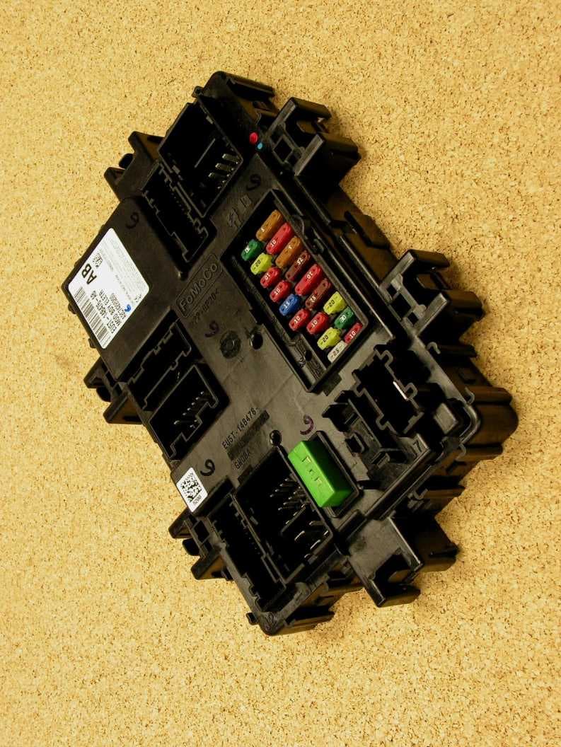
Click to zoom
Application Details
- Equipment Class
- CYY - Communications Receiver used w/Pt 15 Transmitter
- Date of Grant
- Mar 10, 2014
- Application Purpose
- Original Equipment
- Date of Application
- Mar 10, 2014
- Equipment Note
- Automotive Keyless Entry Receiver
- Frequency Range
- 433.90000000 - 433.90000000
- Country
- United States
Documents & Files
Document Text
Text extracted from the exhibit documents filed with the FCC. Open a document above to read the original.
Users Manual
The device under test is manufactured by the grantee (Continental Corporation) and sold as an OEM product. Per 47 CFR 2.909, 2.927, 2.931, 2.1033, 15.15(b) etc..., the grantee must ensure the end-user has all applicable / appropriate operating instructions. When end-user instructions are required, as in the case of this product, the grantee must notify the OEM to notify the enduser. Continental Corporation will supply this document to the reseller/distributor dictating what must be included in the end user’s manual for the commercial product. INF ORMATION TO BE INCLUDED IN THE END USER'S MANUAL The following information (in blue) must be included in the end product user’s manual to ensure continued FCC and Industry Canada regulatory compliance. The ID numbers must be included in the manual if the device label is not readily accessible to the end user. The compliance paragraphs below must be included in the user's manual. ****************************************************************************** FCC ID: M3N74295202 CAN RSS-Gen/CNR-Gen This device complies with Part 15 of the FCC Rules and with Industry Canada license-exempt RSS standard(s). Operation is subject to the following two conditions: (1) This device may not cause harmful interference, and (2) This device must accept any interference received, including interference that may cause undesired operation. Le présent appareil est conforme aux CNR d'Industrie Canada applicables aux appareils radio exempts de licence. L'exploitation est autorisée aux deux conditions suivantes: (1) l'appareil ne doit pas produire de brouillage, et (2) l'utilisateur de l'appareil doit accepter tout brouillage radioélectrique subi, même si le brouillage est susceptible d'en compromettre le fonctionnement. Note: Changes or modifications not expressively approved by the party responsible for compliance could void the user's authority to operate the equipment. The term “IC:” before the radio certification number only signifies that Industry Canada technical specifications were met. ******************************************************************************
Cover Letter(s)
REQUEST FOR CONFIDENTIALITY Pursuant to FCC 47 CRF 0.457(d) and 0.459 and IC RSP-100, Section 10, Continental requests that a part of the subject application be held confidential. Continental has spent substantial effort in developing this product and it is one of the first of its kind in industry. Having the subject information easily available to "competition" would negate the advantage they have achieved by developing this product. Not protecting the details of the design will result in financial hardship. Type of Confidentiality RequestedExhibit Short TermPermanent(1)ID Label & Location Permanent Confidentiality:Continentalrequests the exhibits listed above as permanently confidential be permanently withheld from public review. Short-Term Confidentiality (FCC Only):Continental requests the exhibits selected above as short term confidential be withheld from public view for a period of 45 days from the date of the Grant of Equipment Authorization and prior to marketing. If there are any questions regarding this request, please contact me at the above address or call 734-483- 4211, fax 734-647-2106 or e-mail [email protected]. Sincerely, Valdis V. Liepa, Research Scientist University of Michigan Short TermPermanent(3)External Photos Short TermPermanent 1 (4)Block Diagram Short TermPermanent(5)Schematics Short TermPermanent(7)Test Setup Photos Short TermPermanent(8)User’s Manual Short TermPermanent(9)Internal Photos Short TermPermanent(10)Parts List & Placement Short TermPermanent(11)RF Exposure Short TermPermanent 1 (12)Description of Operation (partial) 1. Block Diagram includes internal oscillator frequency information that the manufacturer considers to be proprietary. Re:Certification for Continental Receiver FCC ID: M3N74063103
ID Label/Location Info
Ignition Switch– Directly read the ignition switch and provides the statusover the HS-CAN bus. Key-In Position– Directly read the key-in switch and provide the statusover the HS-CAN bus. Lift glass Release– monitor lift glass release buttonand provide hardwired output for lift glass release. Diagnostics–14229 Operational Mode Management (OMM)– hardware (Run/ACC relay, Run/Start relay and Run bus) and software support. Safety Beacon System (SBS)– Interface to RCM via CAN to activate horn and flash the hazards. Wake-Up– signal to PCM and Transmission control module relays for power upon BCM wake-up Immobilizer / PATS– Recognizes valid start command and authorizes PCM to start. Energy Management– Determine optimum system voltage and control input to PCM for alternator charging control. RF Receiver-RKE Key fob for lock/unlock and alarm 315 Single channel & 434 MHz multichannel. c) Product Mechanical View: Position 1 Position 2 Position3
Operational Description
The Body Control Module (BCM), which is the heart of the vehicle electrical architecture, integrates a fused electrical bus center for power distribution and a body computer in a single module. This integration concept is designed to streamline and optimize wiring and wiring connections by removing redundant power feeds, increase the sharing of fusing, and to fully utilize the capability of electronics and module foundation by including multiple functions within the same housing thereby re-using microcontroller, power supply, transient protections, housing, brackets, etc. The BCM contains the following main parts: Electronic Body Function Controller-Many of the body and light functions are controlled by the BCM. Switching and Fuse Block-The BCM will handle fusing and switching of loads in the vehicle. Electromechanical relays or power MOSFETs are used for the switching. Electrical Junction and Distribution Block-The BCM acts as a connection block between several cable harnesses. It is also the source of the different voltages used in the electrical distribution system, based upon Power Mode. The sequencing of voltages at start-up and shut down is controlled by the BCM. The BCM module contains one six layer,1oz copper, FR4 Board PCB enclosed in a single plastic housing, PCB mounted relays as well as fuse forks to interface with the Serviceable fuses and circuit breaker, Power Supply, Microcontrollers, Communication ICs, Power Drivers, and interface circuits for analog and digital inputs.All variants of the BCMshare common PCB. The population of the electronics components on the PCBs is variant dependent. There is one power feed to this module. The BCM has a Logic Ground and Power Ground, which is used for the GND reference for the Door Locking H-Bridge Outputs. The module communicates with the other vehicle electronic devices via high speed CAN, 4 LIN Channels. In addition, the module controls and processes several digital and analog inputs and outputs. The electronic and embedded control portion of the BCM controls typical body computer functions such as: Interior Lighting– Courtesy Lighting, Switch Backlighting with PWM dimming, Demand Lighting. Exterior Lighting– Headlamps, Turn/Hazard Lamps, Stop Lamps and CHMSL, ParkLamps, Reverse Lighting. Safety/Security–Panic Alarm, Door Lock/Unlock, Anti-Theft Alarm. Power Door Locks–Control for all door locks via key fob, Lock/Unlock Switches, Auto locking. Battery saver– turns off power to High beam, Low beam, Park & Interior lamp and demand lighting loads after a predetermined period of time Delayed Accessory– provides power to certain vehicle accessories (not limited to radio, power windows) for a prescribed period of time provided certain conditions are present. Driver information– provides low brake fluid, park brake, and door ajar switch status to the instrument cluster and message center over the HS-CAN bus. HSCAN Serial Interface– vehicle network communication link for diagnostics and inter-module communication. LIN– There are four LIN busses– LIN_01 is dedicated for PATS, LIN_02 for WIPER, LIN_03 for SIM and LIN_04 reserved for BMS. Brake Shift Interlock– activate the brake shift interlock solenoid under specified functional spec conditions. Ignition Switch– Directly read the ignition switch and provides the statusover the HS-CAN bus. Key-In Position– Directly read the key-in switch and provide the statusover the HS-CAN bus. Lift glass Release– monitor lift glass release buttonand provide hardwired output for lift glass release. Diagnostics–14229 Operational Mode Management (OMM)– hardware (Run/ACC relay, Run/Start relay and Run bus) and software support. Safety Beacon System (SBS)– Interface to RCM via CAN to activate horn and flash the hazards. Wake-Up– signal to PCM and Transmission control module relays for power upon BCM wake-up Immobilizer / PATS– Recognizes valid start command and authorizes PCM to start. Energy Management– Determine optimum system voltage and control input to PCM for alternator charging control. RF Receiver-RKE Key fob for lock/unlock and alarm 315 Single channel & 434 MHz multichannel. c) Product Mechanical View: Position 1 Position 2 Position3 Upper housing: plastic PP GF-20. Lower housing: plastic PP-T40.
Test Report
Date of Issue: March 2, 2014Prepared For: Continental Automotive Systems US Inc.Test Report No.: 417124-668 The University of Michigan Radiation Laboratory 3228 EECS Building Ann Arbor, Michigan 48109-2122 USA Tel: (734) 483-4211 Fax: (734) 647-2106 e-mail: [email protected] Testing of Electromagnetic Emissions per USA: CFR Title 47, Part 15.109 Canada: IC RSS-GENe are herein reported for Continental Automotive Systems US Inc. 74295202 Test Report No.: 417124-668 Copyright c ©2014 Applicant/Provider: Continental Automotive Systems US Inc. 2400 Executive Hills Drive, Auburn Hills Michigan 48326-2980 USA Phone: +1 (248) 764-6522, Fax: +1 (248) 764-7281 Contact Person: David Reimus; [email protected] Report by: Report Date of Issue: March 2, 2014 Dr. Valdis V. Liepa Results of testing completed on (or before) March 2, 2014 are as follows. Emissions:Radiated spurious emissions associated with the receive chain of this deviceCOMPLYthe regula- tory limit(s) by no less than 7.4 dB. The University of Michigan Radiation Laboratory, 3228 EECS Building, Ann Arbor, Michigan 48109-2122 USAPage 1 of 11 Date of Issue: March 2, 2014Prepared For: Continental Automotive Systems US Inc.Test Report No.: 417124-668 Contents 1 Test Specifications, General Procedures, and Location3 1.1 Test Specification and General Procedures . . . . . . . . . . . . . . . . . . . . . . . . . . . . . . . . . .3 1.2 Test Location and Equipment Used . . . . . . . . . . . . . . . . . . . . . . . . . . . . . . . . . . . . . .4 2 Configuration and Identification of the Equipment Under Test5 2.1 Description and Declarations . . . . . . . . . . . . . . . . . . . . . . . . . . . . . . . . . . . . . . . . .5 2.1.1EUT Configuration . . . . . . . . . . . . . . . . . . . . . . . . . . . . . . . . . . . . . . . . . . .5 2.1.2Modes of Operation . . . . . . . . . . . . . . . . . . . . . . . . . . . . . . . . . . . . . . . . . .5 2.1.3Variants . . . . . . . . . . . . . . . . . . . . . . . . . . . . . . . . . . . . . . . . . . . . . . . . .5 2.1.4Test Samples . . . . . . . . . . . . . . . . . . . . . . . . . . . . . . . . . . . . . . . . . . . . . .6 2.1.5Functional Exerciser . . . . . . . . . . . . . . . . . . . . . . . . . . . . . . . . . . . . . . . . . .6 2.1.6Modifications Made . . . . . . . . . . . . . . . . . . . . . . . . . . . . . . . . . . . . . . . . . .6 2.1.7Production Intent . . . . . . . . . . . . . . . . . . . . . . . . . . . . . . . . . . . . . . . . . . .6 2.1.8Declared Exemptions and Additional Product Notes . . . . . . . . . . . . . . . . . . . . . . . .6 3 Emissions7 3.1 General Test Procedures . . . . . . . . . . . . . . . . . . . . . . . . . . . . . . . . . . . . . . . . . . . .7 3.1.1Radiated Test Setup and Procedures . . . . . . . . . . . . . . . . . . . . . . . . . . . . . . . . .7 3.1.2Conducted Emissions Test Setup and Procedures . . . . . . . . . . . . . . . . . . . . . . . . . .9 3.1.3Power Supply Variation . . . . . . . . . . . . . . . . . . . . . . . . . . . . . . . . . . . . . . . .9 3.2 Unintentional Emissions . . . . . . . . . . . . . . . . . . . . . . . . . . . . . . . . . . . . . . . . . . . . 10 3.2.1Radiated Receiver Spurious . . . . . . . . . . . . . . . . . . . . . . . . . . . . . . . . . . . . . . 10 List of Tables 1The University of Michigan Radiation Laboratory Equipment List.. . . . . . . . . . . . . . . . . . .4 2EUT Declarations. . . . . . . . . . . . . . . . . . . . . . . . . . . . . . . . . . . . . . . . . . . . . . . .5 3Receiver Chain Spurious Emissions≥30 MHz.. . . . . . . . . . . . . . . . . . . . . . . . . . . . . . 10 List of Figures 1Photos of EUT.. . . . . . . . . . . . . . . . . . . . . . . . . . . . . . . . . . . . . . . . . . . . . . . .5 2EUT Test Configuration Diagram. . . . . . . . . . . . . . . . . . . . . . . . . . . . . . . . . . . . . . .6 3Radiated Emissions Diagram of the EUT. . . . . . . . . . . . . . . . . . . . . . . . . . . . . . . . . . .7 4Radiated Emissions Test Setup Photograph(s). . . . . . . . . . . . . . . . . . . . . . . . . . . . . . . .8 5Receiver LO (or 2 x LO = VCO) relative emission.. . . . . . . . . . . . . . . . . . . . . . . . . . . . 11 The University of Michigan Radiation Laboratory, 3228 EECS Building, Ann Arbor, Michigan 48109-2122 USAPage 2 of 11 Date of Issue: March 2, 2014Prepared For: Continental Automotive Systems US Inc.Test Report No.: 417124-668 1 Test Specifications, General Procedures, and Location 1.1 Test Specification and General Procedures The ultimate goal of Continental Automotive Systems US Inc. is to demonstrate that the Equipment Under Test (EUT) complies with the Rules and/or Directives below. Detailed in this report are the results of testing the Conti- nental Automotive Systems US Inc. 74295202 for compliance to: Country/RegionRules or DirectiveReferenced Section(s) United StatesCode of Federal RegulationsCFR Title 47, Part 15.109 CanadaIndustry CanadaIC RSS-GENe In association with the rules and directives outlined above, the following specifications and procedures are fol- lowed herein. ANSI C63.4-2003 ”Methods of Measurement of Radio-Noise Emissions from Low-Voltage Electri- cal and Electronic Equipment in the Range of 9 kHz to 40 GHz” The University of Michigan Radiation Laboratory, 3228 EECS Building, Ann Arbor, Michigan 48109-2122 USAPage 3 of 11 Date of Issue: March 2, 2014Prepared For: Continental Automotive Systems US Inc.Test Report No.: 417124-668 1.2 Test Location and Equipment Used Test LocationThe EUT was fully tested byThe University of Michigan Radiation Laboratory, 3228 EECS Building, Ann Arbor, Michigan 48109-2122 USA. The Test Facility description and attenuation characteristics are on file with the FCC Laboratory, Columbia, Maryland (FCC Reg. No: 91050) and with Industry Canada, Ottawa, ON (File Ref. No: IC 2057A-1). Test EquipmentPertinent test equipment used for measurements at this facility is listed in Table 1. The quality system employed at The University of Michigan Radiation La…
Text truncated - open the document above for the full version.
Contact Information
Applicant
Mark Kenney
Technical Contact
The University of Michigan Radiation LaboratoryValdis V Liepa
[email protected]7344834211
3228 EECS Building · Ann Arbor, Michigan · United States
Test Firm
University of MichiganValdis Liepa
Technical Specifications
| # | Rule Parts | Frequency Range | Power Output |
|---|---|---|---|
| 1 | 15B | 433.9 MHz - 433.9 MHz | - |
Other Applications from Continental Automotive Systems, Inc.
M3NA2C786860
Dec 03, 2023LF Transmitter
Equipment Class
DCD - Part 15 Low Power Transmitter Below 1705 kHz
M3NRHT433
Jul 04, 2022KeyFob
Equipment Class
DSC - Part 15 Security/Remote Control Transmitter
M3NRCKF2B
Apr 25, 2021RCKF2B
Equipment Class
DSC - Part 15 Security/Remote Control Transmitter
M3NWXRFHM1
Jan 28, 2021FCA WL/WS PASE System MY 2021
Equipment Class
DCD - Part 15 Low Power Transmitter Below 1705 kHz
M3NMAS433
Jan 20, 2021Car Key
Equipment Class
DSR - Part 15 Remote Control/Security Device Transceiver