M3U-WVLWireless Valve Link
Hunter Industries Inc
Click to zoom
Application Details
- Equipment Class
- DTS - Digital Transmission System
- Date of Grant
- Aug 18, 2024
- Application Purpose
- Original Equipment
- Date of Application
- Aug 15, 2024
- Equipment Note
- Wireless Valve Link
- Frequency Range
- 914.96800000 - 921.00000000
- Company
- Hunter Industries Inc
- Country
- United States
Documents & Files
Document Text
Text extracted from the exhibit documents filed with the FCC. Open a document above to read the original.
Users Manual
WVL Installation Draft You will need: • WVOM Bluetooth App (free download from Apple or Google Play) • WVOM module installed in ICC2 or HCC controller (press the Reset button on the facepack after installation) • 9VDC batteries (2 per valve, recommended) • 1.5”/38 mm hole saw (included with each WVOM) • Irrigation-grade waterproof connectors Exploded view to call out components and possible replacement parts. The Hunter WVL (Wireless Valve Link) system is a wireless output option for Hunter ICC2 and HCC controllers. WVL requires a Hunter WVOM (Wireless Valve Output Module) or WVOM-E (international versions) installed in a controller output module slot. Verify that the WVOM module is installed in the controller. Make sure the WVL programming app is installed on your smartphone. (link) Prepare remote access to the controller. • ROAM or ROAM-XL • Centralus with mobile access • Hydrawise with mobile access WVL Functions and Features The control link has 2 buttons and 2 LED lights in the battery compartment. These can perform the following functions, in order of importance. Station Assignment and Comm Check require the installation of a WVOM in the controller. Feature Function Button & Process 1 Station Assignment (REQUIRED) Assigns controller station numbers to individual output links Right, 2 secs. 2 Site Survey/Comm Check Checks radio coverage at proposed installation location Left, 3 times 3 Manual Station Test Tests solenoid connections and operation directly from the WVL Left, 2 secs. 4 Factory Reset Erases all programming and assignments Right, insert batt and hold 5 secs Station Assignment Bring the WVL to be programmed near the controller location (before installing in the valve box). This insures solid communications, before moving to the field location. Unscrew the battery cover retaining ring. Remove the waterproof cap to reveal the battery compartment. Install the first battery. You will need to access the right button for station assignment, so installing the first battery on the left is recommended to allow easier access to the button. Press and hold the right button for approximately 2 seconds. The right LED should turn yellow/green, showing the WVL is in assignment mode. Within 5 minutes, use the mobile app to add a new station, and allow it to scan for stations in assignment mode. Note: Address one module at a time, to avoid duplicate addresses or confusion. After 5 minutes, the WVL will exit the assignment mode. Note: Duplicate Addresses should not be used in the WVL system! Procedure • Place WVL in assignment mode (press and hold right button for 2 seconds until right LED is yellow.) • Open app, scan and connect to the controller. When connected, the screen will show a list of any WVLs already connected. • Press add (+) to add a WVL and then press the Scan button. The controller will scan for a WVL that is currently in assignment mode, and display the station numbering options in the app. • Use the app to select the controller station numbers to assign to the WVL. Click Done for each station when it is assigned. • When the station assignments for the WVL are as desired, press the Save button. The controller (WVOM) will transmit to the WVL to complete the assignment, and the app show if the save was successful. The assignment (right) light in the WVL will also flash yellow several times when the assignment is successful. • After a successful save, take the WVL to the field location. • Install and connect the WVL outputs to Hunter DC solenoids. Observe red/black wire polarity. Install a second 9VDC battery if desired for improved seasonal battery life (recommended). WVL Status Check See the status of any WVL, with at least 1 battery installed. Press and release the Assignment button once. Do not hold the button down. The Assignment light will show green if stations have been assigned, and red if not. The left (Manual) light will show battery status: green if battery is good, and red if it needs replacement. Site Survey/Comm Check You can verify radio coverage at the proposed installation/valve box site, prior to installation. Move the programmed controller to the valve box location, and position it as closely to the final installation as possible. With the battery compartment open, install at least one battery. Press the left (manual) button 3 times. The LED will blink amber every 2 seconds to show it is listening for the WVOM signal. Send a manual station start command to any WVL in the system (from the controller dial, with a helper, with a Hunter ROAM or ROAM-XL remote, or smartphone via central if that is an option). • The LED will turn green if it hears the LoRa radio commands from the WVOM. This indicates a probable successful location. • If it does not turn green within a few seconds after the WVOM has sent a command, the signal was not heard. o If the command was sent to the WVL being tested, the LED will turn red o Improve the signal (elevate controller antenna, or add a repeater), or the location may not work reliably. Installation Complete the above steps first, especially station assignment. Then proceed to install and connect the WVL in the valve box. Plan ahead to allow sufficient clearance in the valve box (show dimensions) before drilling. Verify that the WVL assembly will fit in the valve box area without interfering with the valve or other devices in the box. Final installation requires a minimum 4.25”/10.8 cm diameter, and 6.25”/15.9 cm vertical clearance, below the valve box lid. Determine the center point for the WVL, and drill or use the 1 ½” (38 mm) hole saw (supplied with each WVOM) into the valve box lid on the center of the WVL location. Note: It is better to drill upward from the underside of the valve box lid, to avoid any reinforcement ribs if possible. Note: Additional trimming or modifications may be required, depending on the lid material and design. For plastic or fiberglass lids, a handheld jig saw can remove internal ribs that a hole saw ca…
Text truncated - open the document above for the full version.
Attestation Statements
HUNTER INDUSTRIES 1940 Diamond Street San Marcos, CA 92078 1 760-744-5240 Main 1 800-733-2823 Support 1 760-744-7461 Fax hunterindustries.com February 1, 2024 Federal Communications Commissions Authorization and Evaluation Division 7435 Oakland Mills Road Columbia, MD 21046 RE: CFR 47 §2.911 (d)(7) Agent Designation Attestation FCC ID: M3U-WVL, M3URPT, and M3U-WVOM To Whom It May Concern: Hunter Industries Inc. (“the applicant”) as required by section §2.911(d)(7), will also serve as the agent for service of process for the above referenced FCC IDs. The applicant acknowledges that they will maintain an agent for no less than one year after the grantee has terminated all marketing and importation or the conclusion of any Commission-related proceeding involving the equipment. The applicant further acknowledges their responsibility under CFR 47 §2.929(c) to inform the FCC whenever the agent information changes. Satoshi Kuwahara Hunter Industries Inc. FCC FRN: 0011558756 1940 Diamond St, San Marcos, CA 92078 [email protected] Best Regards, Satoshi Kuwahara, Director Product Integrity Hunter Industries, Inc 1940 Diamond St, San Marcos, CA 92078
Attestation Statements
HUNTER INDUSTRIES 1940 Diamond Street San Marcos, CA 92078 1 760-744-5240 Main 1 800-733-2823 Support 1 760-744-7461 Fax hunterindustries.com February 1, 2024 Federal Communications Commissions Authorization and Evaluation Division 7435 Oakland Mills Road Columbia, MD 21046 RE: CFR 47 §2.911 (d)(5) Attestation FCC ID: M3U-WVL, M3URPT, and M3U-WVOM Hunter Industries Inc. (“the applicant”) certifies that the equipment for which authorization is sought is not “covered” equipment prohibited from receiving an equipment authorization pursuant to section 2.903 of the FCC rules. Hunter Industries Inc. (“the applicant”) certifies that, as of the date of the filing of the application, the applicant is not identified on the Covered List as an entity producing “covered” equipment and is not an affiliate or subsidiary of an entity identified on the Covered List. Best Regards Satoshi Kuwahara Director Product Integrity Hunter Industries, Inc
Cover Letter(s)
HUNTER INDUSTRIES 1940 Diamond Street San Marcos, CA 92078 1 760-744-5240 Main 1 800-733-2823 Support 1 760-744-7461 Fax hunterindustries.com August 4, 2024 Attn: FCC Office of Engineering and Technology / UL Verification Services TCB Subject: Request for Confidentiality FCC ID: M3U-WVL, M3URPT and M3U-WVOM To Whom It May Concern: Pursuant to the provisions of Sections 0.457 and 0.459 of the Commission’s rules (47 CFR §§ 0.457, 0.459), we are requesting the Commission to withhold the following attachments as confidential document from public disclosure indefinitely. • Schematic Diagram • Block Diagram • Theory of Operation Above mentioned document contains detailed system and equipment description are considered as proprietary information in operation of the equipment. The public disclosure of above documents might be harmful to our company and would give competitor an unfair advantage in the market. It is our understanding that all measurement test reports, FCC ID label format and correspondent during certification review process cannot be granted as confidential documents and those information will be available for public review once the grant of equipment authorization is issued. Best Regards, Satoshi Kuwahara, Director Product Integrity Hunter Industries, Inc
Cover Letter(s)
HUNTER INDUSTRIES 1940 Diamond Street San Marcos, CA 92078 1 760-744-5240 Main 1 800-733-2823 Support 1 760-744-7461 Fax hunterindustries.com January 5, 2024 UL LLC 12 Laboratory Dr. Research Triangle Park, NC 27709 USA To whom it may concern: I, the undersigned, hereby authorize UL LLC to act on our behalf in all manners relating to application for equipment authorization, including signing of all documents relating to these matters. Any and all acts carried out by UL LLC on our behalf shall have the same effect as acts of our own. I, the undersigned, hereby certify that we are not subject to a denial of federal benefits, that includes FCC benefits, pursuant to Section 5301 of the Anti-Drug Abuse Act of 1988, 21 U.S.C. 853(a). In authorizing UL LLC as our representative, we still recognize that we are responsible to: a) fulfill the requirements for the scope of certification requested, including implementing any appropriate changes requested by UL Verification Services Telecommunications Certification Body (TCB) and / or the FCC; b) supply any and all information needed for the evaluation of the products for which certification is sought; c) make claims regarding certification only in respect of the scope for which certification has been granted; d) not use our product certification in such a manner as to bring the TCB or FCC into disrepute and to not make any statement regarding product certification which the TCB or FCC may consider misleading or unauthorized; e) discontinue use of all advertising matter that contains any reference thereto and complies with any and all actions required by the FCC upon suspension or cancellation of certification; f) use certification only to indicate that products are certified in conformity with specified standards; g) endeavor to ensure that no certificate or report or any part thereof is used in a misleading manner, and any copies of the grants/certificates shall be reproduced in their entirety; h) comply with the requirements of the TCB and FCC, including the use of marks and label information prescribed for the scope of certification, when making reference to product certification in communication media such as documents, brochure or advertisements; i) comply with the requirements for certification, supply any information needed for evaluation of products to be certified and, where applicable, make provision for the participation of observers; j) ensure that products marketed under the scope of the requested certification continue to comply with the certification requirements; k) provide a sample of a production unit for testing within 30 days of the request should this product be selected as part of either the TCB’s or the FCC’s market surveillance requirements; l) keep a record of all complaints relating to product’s compliance with requirements of relevant standard; make records available to UL or FCC when requested; take appropriate action with respect to such complaints and any deficiencies found in the product that affect compliance with requirements for certification; document the actions taken with respect to complaints and/or deficiencies; m) inform the TCB immediately of any changes that may affect its ability to comply with the certification requirements. This authorization is valid until further written notice from the applicant. Sincerely Yours, Satoshi Kuwahara, Director Product Integrity Hunter Industries, Inc.
ID Label/Location Info
FCC ID and IC ID LABEL AND LOCATION LABEL Side of EUT FCC Label Location/Affixation Label is a laminated sticker label affixed using adhesive.
RF Exposure Info
FCC Part 1 Subpart I FCC Part 2 Subpart J RSS 102 ISSUE 5 RF EXPOSURE REPORT FOR WIRELESS VALVE LINK SYSTEM MODEL NUMBER: WVL-400, WVL-200, WVL-100 FCC ID: M3U-WVL IC: 2772A-WVL REPORT NUMBER: R13592063-E1 ISSUE DATE: 2024-07-08 Prepared for HUNTER INDUSTRIES 1940 DIAMOND STREET SAN MARCOS, CA 92078-5120, USAS Prepared by UL LLC 12 LABORATORY DR. RESEARCH TRIANGLE PARK, NC 27709 USA TEL: (919) 549-1400 REPORT NO: R13592063-E1 DATE: 2024-07-08 FCC ID: M3U-WVL IC: 2772A-WVL Page 2 of 11 UL LLC FORM NO: 03-EM-F00858 12 Laboratory Dr., RTP, NC 27709 TEL: (919) 549-1400 This report shall not be reproduced except in full, without the written approval of UL LLC. REVISION HISTORY Rev. Issue Date Revisions Revised By V1 2021-09-10 Initial Issue Brian T. Kiewra V2 2024-07-08 Updated Antenna Gain and Power Noah Bennett REPORT NO: R13592063-E1 DATE: 2024-07-08 FCC ID: M3U-WVL IC: 2772A-WVL Page 3 of 11 UL LLC FORM NO: 03-EM-F00858 12 Laboratory Dr., RTP, NC 27709 TEL: (919) 549-1400 This report shall not be reproduced except in full, without the written approval of UL LLC. TABLE OF CONTENTS REVISION HISTORY ..................................................................................................................2 TABLE OF CONTENTS .............................................................................................................3 1. ATTESTATION OF TEST RESULTS ..................................................................................4 2. TEST METHODOLOGY ......................................................................................................5 3. REFERENCES ....................................................................................................................5 4. FACILITIES AND ACCREDITATION ..................................................................................5 5. DECISION RULES AND MEASUREMENT UNCERTAINTY ...............................................6 5.1. METROLOGICAL TRACEABILITY ...............................................................................6 5.2. DECISION RULES ........................................................................................................6 5.3. MEASUREMENT UNCERTAINTY ................................................................................6 6. MAXIMUM PERMISSIBLE EXPOSURE (LIMITS AND EQUATIONS) ................................7 6.1. FCC RULES .................................................................................................................7 6.2. ISED RULES ................................................................................................................8 6.3. EQUATIONS .................................................................................................................9 7. RF EXPOSURE RESULTS ................................................................................................11 END OF TEST REPORT ..........................................................................................................11 REPORT NO: R13592063-E1 DATE: 2024-07-08 FCC ID: M3U-WVL IC: 2772A-WVL Page 4 of 11 UL LLC FORM NO: 03-EM-F00858 12 Laboratory Dr., RTP, NC 27709 TEL: (919) 549-1400 This report shall not be reproduced except in full, without the written approval of UL LLC. 1. ATTESTATION OF TEST RESULTS COMPANY NAME: Hunter Industries 1940 Diamond Street San Marcos, CA 92078-5120 EUT DESCRIPTION: Wireless Valve Link System MODEL: WVL-400, WVL-200, WVL-100 SERIAL NUMBER: Non-Serialized SAMPLE RECEIPT DATE: 2021-07-28 DATE TESTED: 2021-08-30 APPLICABLE STANDARDS STANDARD TEST RESULTS FCC PART 1 SUBPART I & PART 2 SUBPART J Complies RSS 102 ISSUE 5 Complies UL LLC. tested the above equipment in accordance with the requirements set forth in the above standards. The test results show that the equipment tested is capable of demonstrating compliance with the requirements as documented in this report. The results documented in this report apply only to the tested sample, under the conditions and modes of operation as described herein. It is the manufacturer's responsibility to assure that additional production units of this model are manufactured with identical electrical and mechanical components. All samples tested were in good operating condition throughout the entire test program. Measurement Uncertainties are published for informational purposes only and were not taken into account unless noted otherwise. This document may not be altered or revised in any way unless done so by UL LLC. and all revisions are duly noted in the revisions section. Any alteration of this document not carried out by UL LLC. will constitute fraud and shall nullify the document. Approved & Released For UL LLC By: Prepared By: Michael Antola Brian T. Kiewra Staff Engineer Project Engineer Consumer Technology Division Consumer Technology Division UL LLC UL LLC REPORT NO: R13592063-E1 DATE: 2024-07-08 FCC ID: M3U-WVL IC: 2772A-WVL Page 5 of 11 UL LLC FORM NO: 03-EM-F00858 12 Laboratory Dr., RTP, NC 27709 TEL: (919) 549-1400 This report shall not be reproduced except in full, without the written approval of UL LLC. 2. TEST METHODOLOGY All calculations were made in accordance with FCC Parts 1.1310, 2.1091, 2.1093, KDB 447498 D01 v06, KDB 447498 D03 V01, IEEE Std C95.1-2005, IEEE Std C95.3-2002, IC Safety Code 6 and RSS 102 Issue 5. 3. REFERENCES Output power and Antenna gain data is excerpted from product documentation provided by the applicant. 4. FACILITIES AND ACCREDITATION UL LLC is accredited by A2LA, certification # 0751.06, for all testing performed within the scope of this report. Testing was performed at the locations noted below. Address ISED CABID ISED Company Number FCC Registration ☐ Building: 12 Laboratory Dr RTP, NC 27709, U.S.A US0067 2180C 703469 ☒ Building: 2800 Perimeter Park Dr. Suite B Morrisville, NC 27560, U.S.A 27265 REPORT NO: R13592063-E1 DATE: 2024-07-08 FCC ID: M3U-WVL IC: 2772A-WVL Page 6 of 11 UL LLC FORM NO: 03-EM-F00858 12 Laboratory Dr., RTP, NC…
Text truncated - open the document above for the full version.
Test Report
This document is issued by the Company subject to its General Conditions of Service printed overleaf, available on request or accessible at http://www.sgs.com/en/Terms-and-Conditions/General-Conditions-of-Services-NorthAm.aspx and, for electronic format documents, subject to Terms and Conditions for Electronic Documents at http://www.sgs.com/en/Terms-and-Conditions/terms-e-document.aspx. Attention is drawn to the limitation of liability, indemnification and jurisdiction issues defined therein. Any holder of this document is advised that information contained hereon reflects the Company’s findings at the time of its intervention only and within the limits of Client’s instructions, if any. The Company’s sole responsibility is to its Client and this document does not exonerate parties to a transaction from exercising all their rights and obligations under the transaction documents. This document cannot be reproduced except in full, without prior written approval of the Company. Any unauthorized alteration, forgery or falsification of the content or appearance of this document is unlawful and offenders may be prosecuted to the fullest extent of the law. Unless otherwise stated, the results shown in this test report refer only to the sample(s) tested and such sample(s) are retained until the customer requests them to be shipped back or SGS contacts the customer for approval to return them. SGS North America, Inc. Test Report Report No.: 208845 Date: May 23, 2024 Page 1 of 13 SGS BOSS No.: 5183686 Manufacturer’s Name: Hunter Industries The following sample(s) was/were submitted and identified by/on-behalf of the client as a mobile terminal device. Product Name 902 MHz – 928 MHz Antenna Model Name 906900 Description The 902 – 928 MHz Antenna was tested alone, but is mounted inside the device models WVL and RPT Board S/N N/A Testing Start Date 05/15/2024 Testing End Date 05/15/2024 Test(s) Requested Passive Antenna Performance Signed for and on behalf of SGS North America, Inc. Sergio Garcia Fred Jeong __ Senior Engineer OTA Lab Manager General Conditions of Service for North America 1. General (a) Unless otherwise agreed in writing or except where they are at variance with (i) the regulations governing services performed on behalf of governments, government bodies or any other public entity or (ii) the mandatory provisions of local law, all offers or services and all resulting contractual relationship(s) between any of the affiliated companies of SGS North America Inc. or any of their agents (each a “Company”) and Client (the “Contractual Relationship(s)”) shall be governed by these general conditions of service (hereinafter the “General Conditions”). (b) The Company may perform services for persons or entities (private, public or governmental) issuing instructions (hereinafter, the “Client”). © Unless the Company receives prior written instructions to the contrary from Client, no other party is entitled to give instructions, particularly on the scope of the services or the delivery of reports or certificates resulting therefrom (the “Reports of Findings”). Client hereby irrevocably authorize the Company to deliver Reports of Findings to a third party where so instructed by Client or, at its discretion, where it implicitly follows from circumstances, trade custom, usage or practice. 2. Provision of Services (a) The Company will provide services using reasonable care and skill and in accordance with Client’s specific instructions as confirmed by the Company or, in the absence of such instructions: (1) the terms of any standard order form or standard specification sheet of the Company; and/or (2) any relevant trade custom, usage or practice; and/or (3) such methods as the Company shall consider appropriate on technical, operational and/or financial grounds. (b) Information stated in Reports of Findings is derived from the results of inspection or testing procedures carried out in accordance with the instructions of Client, and/or our assessment of such results on the basis of any technical standards, trade custom or practice, or other circumstances which should in our professional opinion be taken into account. © Reports of Findings issued further to the testing of samples contain the Company’s opinion on those samples only and do not express any opinion upon the lot from which the samples were drawn. (d) Should Client request that the Company witness any third party intervention, Client agrees that the Company’s sole responsibility is to be present at the time of the third party’s intervention and to forward the results, or confirm the occurrence, of the intervention. Client agrees that the Company is not responsible for the condition or calibration of apparatus, instruments and measuring devices used, the analysis methods applied, the qualifications, actions or omissions of third party personnel or the analysis results. © Reports of Findings issued by the Company will reflect the facts as recorded by it at the time of its intervention only and within the limits of the instructions received or, in the absence of such instructions, within the limits of the alternative parameters applied as provided for in clause 2(a). The Company is under no obligation to refer to, or report upon, any facts or circumstances which are outside the specific instructions received or alternative parameters applied. (f) The Company may delegate the performance of all or part of the services to an agent or subcontractor and Client uthorizat Company to disclose all information necessary for such performance to the agent or subcontractor. (g) Should Company receive documents reflecting engagements contracted between Client and third parties or third party documents, such as copies of sale contracts, letters of credit, bills of lading, etc., they are considered to be for information only, and do not extend or restrict the scope of the services or the obligations accepted by the Company. (h) Client acknowledges that the Com…
Text truncated - open the document above for the full version.
Test Report
TEST REPORT Report Number: R14967114-E1 Applicant : Hunter Industries 1940 Diamond St. San Marcos, CA 92078, United States Model : WVL-100, WVL-200, WVL-400 FCC ID : M3U-WVL IC : 2772A-WVL EUT Description : Wireless Valve Link Test Standard(s) : FCC 47 CFR PART 15 SUBPART C: 2023 ISED RSS-247 ISSUE 3: 2023 ISED RSS-GEN ISSUE 5 + A2:2021 Date Of Issue: 2024-07-05 Prepared by: UL LLC 12 Laboratory Dr. Research Triangle Park, NC 27709 U.S.A. TEL: (919) 549-1400 REPORT NO: R14967114-E1 DATE: 2024-07-05 FCC ID: M3U-WVL IC: 2772A-WVL Page 2 of 32 UL LLC 12 Laboratory Dr., RTP, NC 27709; USA TEL: (919) 549-1400 This report shall not be reproduced except in full, without the written approval of UL LLC REPORT REVISION HISTORY Rev. Issue Date Revisions Revised By V1 2023-10-27 Initial Issue Charles Moody V2 2024-07-05 Updated Antenna Gain Noah Bennett REPORT NO: R14967114-E1 DATE: 2024-07-05 FCC ID: M3U-WVL IC: 2772A-WVL Page 3 of 32 UL LLC 12 Laboratory Dr., RTP, NC 27709; USA TEL: (919) 549-1400 This report shall not be reproduced except in full, without the written approval of UL LLC TABLE OF CONTENTS REPORT REVISION HISTORY ..................................................................................................2 TABLE OF CONTENTS .............................................................................................................3 1. ATTESTATION OF TEST RESULTS ..................................................................................5 2. TEST RESULTS SUMMARY ...............................................................................................6 3. TEST METHODOLOGY ......................................................................................................6 4. FACILITIES AND ACCREDITATION ..................................................................................6 5. DECISION RULES AND MEASUREMENT UNCERTAINTY ...............................................7 5.1. METROLOGICAL TRACEABILITY ...............................................................................7 5.2. DECISION RULES ........................................................................................................7 5.3. MEASUREMENT UNCERTAINTY ................................................................................7 5.4. SAMPLE CALCULATION .............................................................................................7 6. EQUIPMENT UNDER TEST ................................................................................................8 6.1. EUT DESCRIPTION .....................................................................................................8 6.2. MAXIMUM OUTPUT POWER .......................................................................................8 6.3. DESCRIPTION OF AVAILABLE ANTENNAS ...............................................................8 6.4. SOFTWARE AND FIRMWARE .....................................................................................8 6.5. WORST-CASE CONFIGURATION AND MODE ...........................................................8 6.6. DESCRIPTION OF TEST SETUP .................................................................................9 7. MEASUREMENT METHOD...............................................................................................10 8. TEST AND MEASUREMENT EQUIPMENT ......................................................................11 9. ANTENNA PORT TEST RESULTS ...................................................................................13 9.1. ON TIME AND DUTY CYCLE .....................................................................................13 9.2. 99% BANDWIDTH ......................................................................................................14 9.2.1. LoRa ....................................................................................................................14 9.3. 6 dB BANDWIDTH ......................................................................................................15 9.3.1. LoRa ....................................................................................................................15 9.4. OUTPUT POWER .......................................................................................................16 9.4.1. LoRa ....................................................................................................................16 9.5. AVERAGE POWER ....................................................................................................17 9.5.1. LoRa ....................................................................................................................17 9.6. POWER SPECTRAL DENSITY ..................................................................................18 9.6.1. LoRa ....................................................................................................................18 REPORT NO: R14967114-E1 DATE: 2024-07-05 FCC ID: M3U-WVL IC: 2772A-WVL Page 4 of 32 UL LLC 12 Laboratory Dr., RT…
Text truncated - open the document above for the full version.
Contact Information
Applicant
Satoshi Kuwahara(Director, Product Integrity)
Test Firm
UL LLCSteven Thompson
[email protected]919 549 1430
Technical Specifications
| # | Rule Parts | Frequency Range | Power Output |
|---|---|---|---|
| 1 | 15C | 914.968 MHz - 921 MHz | 28.40 mW |
Other Applications from Hunter Industries Inc
M3URMLR
May 21, 2026Remote
Equipment Class
DTS - Digital Transmission System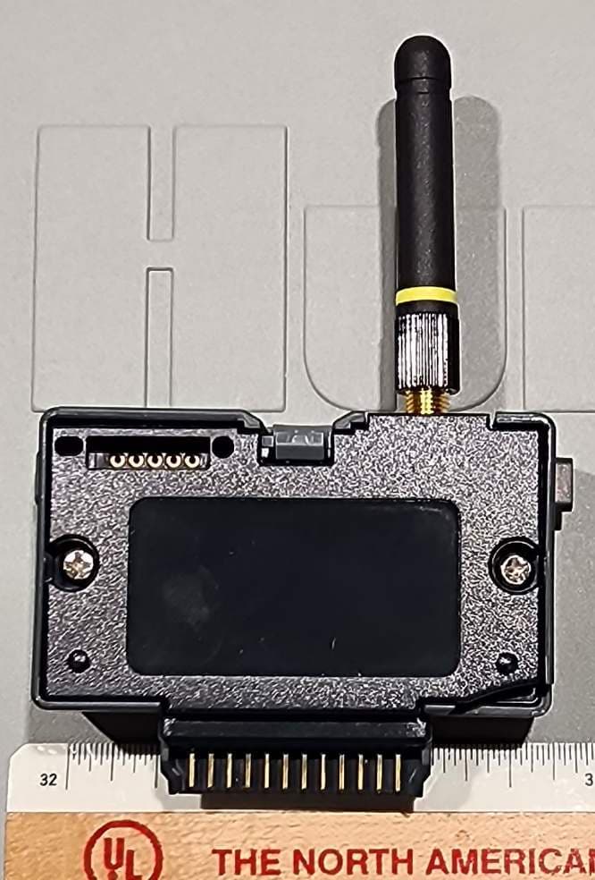
M3UA2CLORA
Apr 28, 2026LoRa Radio Module
Equipment Class
DTS - Digital Transmission System
M3U-WVOM
Aug 18, 2024Quick plug-in controller
Equipment Class
DTS - Digital Transmission System
M3U-RPT
Aug 06, 2024Repeater
Equipment Class
DTS - Digital Transmission System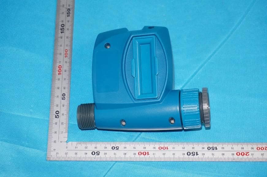
M3UBTT1
Feb 25, 2021Bluetooth Hose Timer
Equipment Class
DTS - Digital Transmission System