M3UICDDECSix Station Decoder
Hunter Industries Inc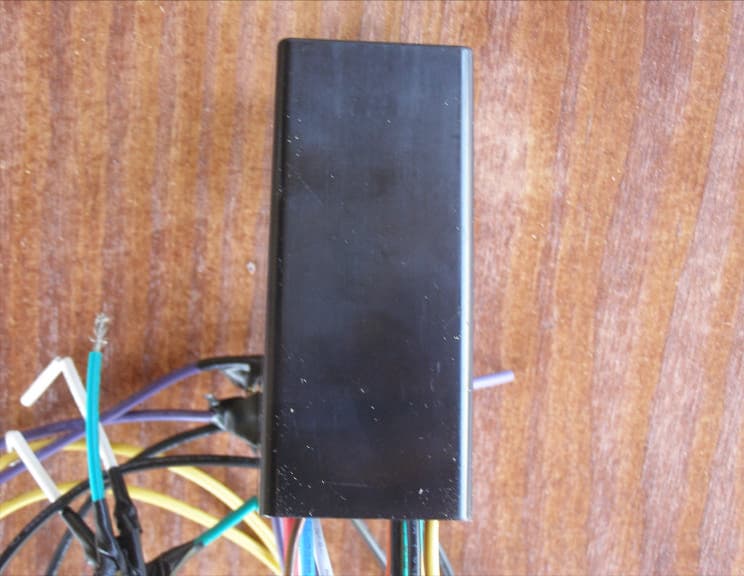
Click to zoom
Application Details
- Equipment Class
- DCD - Part 15 Low Power Transmitter Below 1705 kHz
- Date of Grant
- Apr 19, 2010
- Application Purpose
- Original Equipment
- Date of Application
- Apr 19, 2010
- Equipment Note
- Six Station Decoder
- Frequency Range
- 0.12500000 - 0.12500000
- Company
- Hunter Industries Inc
- Country
- United States
Documents & Files
Document Text
Text extracted from the exhibit documents filed with the FCC. Open a document above to read the original.
Users Manual
ICD400/600 Series Decoder FCC Notice FCC ID: M3UICDDEC This device complies with FCC rules Part 15. Operation is subject to the following two conditions: • This device may not cause harmful interference and • This device must accept any interference received, including interference that may cause undesired operation. This equipment has been tested and found to comply with the limits for class B digital devices, pursuant to part 15 of the FCC Rules. These limits are designed to provide reasonable protection against harmful interference in a residential installation. This equipment generates, uses, and can radiate radio frequency energy and if not installed and used in accordance with the instructions, may cause harmful interference to radio communications. However, there is no guarantee that interference will not occur in a particular installation. If this equipment does cause harmful interference to radio or television reception, which can be determined by turning the equipment on and off, the user is encouraged to try to correct the interference by one or more of the following measures: • Reorient or relocate the receiving antenna • Increase the separation between the equipment and the receiver • Connect the equipment to an outlet on a circuit different from that to which the receiver is connected • Consult the dealer or an experienced radio/TV technician for help The user is cautioned that changes and modification made to the equipment without the approval of the manufacturer could void the user’s authority to operate this equipment. Installation Instructions This package includes: (1) ICD400 or ICD600 decoder module (1) Instruction Sheet Tools/supplies required* (not included): DBRY-6 high-voltage waterproof connectors or equivalent DBY waterproof connectors or equivalent Wire strippers Optional earth grounding hardware The ICD Series decoders may be connected to the Hunter ACC, AGC, Genesis, VSX, and IDS decoder controllers. • In the ACC or AGC controllers, each decoder is programmed with station address(es) at the controller, before installing it in the 2-wire path. These controllers have a programming port on the decoder output module. Program the station number(s) into the decoder, and then write the station number assignments on the metallic tag on the decoder. The 8-digit serial number is not used in the decoder set-up on these controllers. • ICD Decoders may also be programmed with the Hunter Industries Model ICD-HP handheld programmer, after installation. 1. In the ACC/AGC series of controllers, first Insert the red and blue wires from the decoder into the Programming Ports on the decoder output module (ADM99). 2. Use the procedure in the ACC / AGC owner’s manual for addressing decoders. Use a ballpoint pen to write the station number(s) on the decoder’s metallic tag. Each decoder output can power two standard 24VAC Hunter solenoids. They must be wired in parallel, as shown in step 9. • In Genesis, VSX, and IDS controllers, the decoder can be installed on the 2-wire path before giving it a station address using the 7-digit serial number followed by “x”. The 8-digit serial number is required for station addressing Hunter Industries 1940 Diamond Street • San Marcos, California 92078 • TEL (1) 760-744-5240 • Field Services (800) 248-6561 • FAX (1) 760-591-9582 • www.hunterindustries.com • www.huntergolf.com April, 2010 2 on the Genesis, VSX and IDS controllers. • “x” at the end of a serial number is replaced with 1, 2, 3, or 4 in the controller station programming to indicate which colored pair matches the station number (see chart). • Note and record the 8-digit serial number on the decoder body, and then use the controller keypad to indicate which station number(s) will be assigned to the decoder (see controller manual). Installing the decoder: 1. Controller power must be OFF when installing decoders in the 2-wire path. 2. Select the decoder location (unless you are replacing an existing decoder). Decoders should be within 100 feet/33m of the solenoids they will operate. Decoders are waterproof, but should be installed in a valve box to facilitate future service and increase longevity. 3. Locate the 2-Wire path. These are the Red and Blue wires coming from the controller. The wire path must be cut to insert decoder wiring, unless you are replacing an existing decoder. Be sure to leave enough slack in the wire path to allow easy connection of the decoder, and to allow for contraction of wiring due to temperature changes. Hunter recommends at least 5ft./1.5m slack for each decoder, to allow it to be removed from the valve box completely for installation, service, and inspection. 4. Identify the color-coded wires on the decoder. The red & blue wires connect to the red and blue wire path from the controller. 5. Strip the cut red and blue wire ends back approximately ½ inch (12mm). 6. Twist the stripped red wire ends (the ends from the 2-wire path and the decoder) together, and thread securely into the wire nut for the DBRY-6 or equivalent waterproof connector. Seal in accordance with the connector manufacturer’s instructions (insert threaded wire nut connection into waterproof grease, and snap cap securely shut over wires). 7. Repeat with the blue wires: connect the blue end(s) from the 2-wire path with the decoder, and secure in a separate DBRY-6 or equivalent waterproof connector. 8. Each color-coded decoder output operates one or two solenoids up to 150 feet/45m away (greater distances are possible, but increase susceptibility to lightning damage). • Wire runs to the solenoids should be twisted pairs (if solenoids are over 20 ft./7m from decoder) of at least 18 AWG (1mm dia.) wire. The twist in the wire is important, because it is an aid in lightning and surge suppression. Connect each color-coded station output to the desired solenoid(s) as follows: • The non-insulated bare copper wire is the decoder’s grounding wire and is only used on selected decoders. If the plan do…
Text truncated - open the document above for the full version.
Attestation Statements
1 June 5, 2009 Compatible Electronics TCB 114 Olinda Drive Brea, California 92823 Gentlemen: This is a letter of authorization to accept that any personnel of Compatible Electronics, Inc. as an Agent for Hunter Industries Inc. 1940 Diamond Street, San Marcos, CA 92078, for a period of one year, to sign applications before the certification body on our behalf, to make representations to you on our behalf, and to receive and exchange data between our company and the certification body in connection with certification of the following Hunter Industries products: ICD-600 Decoder ICD-400 Decoder ICD-200 Decoder ICD-100 Decoder under FCC Docket Number 20780 and General Docket Number 80-284 pursuant to Part 15 of the FCC Rules and Regulations. Please also accept this letter as an attestation that neither Hunter Industries nor any of its officers, directors, or persons holding 5% or more of the outstanding stock or shares, voting or non-voting, have been denied federal benefits under section 5301 of the Anti-Drug Abuse act of 1988, 21 U.S.C. 853(a). In addition, Hunter Industries will notify the Federal Communications Commission if, at any time, the situation changes causing Hunter Industries to be denied federal benefits. If you have any further questions or need additional information, please feel free to give me a call at 760-744-5240. Sincerely, Peter Woytowitz Engineering Manager, Controllers Hunter Industries
Attestation Statements
2 June 5, 2009 Compatible Electronics TCB 114 Olinda Drive Brea, California 92823 Subject: TCB application submittal Gentlemen: We, Hunter Industries, would like to declare that the application being submitted for the device with FCC ID: M3UICDDEC, has not been submitted to another TCB for certification. The application was submitted to Compatible Electronics TCB on June 5th, 2009. If you have any questions, please do not hesitate to contact us at 760-744-5240. Sincerely, Peter Woytowitz Engineering Manager, Controllers Hunter Industries
Cover Letter(s)
___________________________________________________ Hunter Industries Inc 1940 Diamond Street, San Marcos California 92078 June 5, 2009 Certification and Engineering Bureau Industry Canada P.O. Box 11490, Station H 3701 Carling Avenue (Building 94) Ottawa, Ontario K2H 8S2 Subject: Confidentiality request for IC: 2772A-ICDDEC To Whom It May Concern, Pursuant to sections RSP-100, Section 10, the applicant requests confidential treatment of the following information accompanying this application: Block Diagrams Schematics The above materials contain trade secrets and proprietary information not customarily released to the public. The public disclosure of these matters might be harmful to the applicant and provide unjustified benefits to its competitors. Sincerely, (Peter Woytowitz) Title: Engineering Manager, Controllers email: [email protected] On behalf of: HunterIndustries, Incoporated Telephone: 760-744-5240
Cover Letter(s)
114 OLINDA DRIVE • •• • BREA, CALIFORNIA 92823 • •• • (714) 579-0500 • •• • FAX (714) 579-1850 June 18, 2009 Compatible Electronics TCB 114 Olinda Drive Brea, CA 92823 Subject: Request for Certification of the Hunter Industries, Inc. Decoder System Model: ICD-600 FCC ID: M3UICDDEC Gentlemen: We have enclosed a package for the certification of the Hunter Industries, Inc. Six Station Decoder Model: ICD-600. We have enclosed the completed Form 731 with the applicable exhibits. If you have any questions or need any additional information, please give me a call at (714) 579-0500. Sincerely, Kyle Fujimoto Test Engineer
Cover Letter(s)
Correspondence by Project Project Number: 1248230349 Correspondence Number Memo M3UICDDEC-1 In order for processing of this certification application (FCC ID: M3UICDDEC) to continue, the following issue(s) will have to be addressed: 1) The user’s manual must contain the information to the user contained in section 15.21 of the FCC rules. Response: The owner's manual has been revised to include this. 2) The internal photo exhibit is incomplete. It must contain photographs of both sides of each board. The internal photos have been revised to include the extra photos.
ID Label/Location Info
Hunter Industries Inc. Model:ICD-600 Six Station Decoder FCC ID: M3UICDDEC IC: 2772A-ICDDEC This device complies with part 15 of the FCC Rules. Operation is subject to the following two conditions: (1) This device may not cause harmful interference and (2) This device must accept any interference received, including interference that may cause undesired operation.
Internal Photos
1 Transceiver Circuit Antenna Micro- Controller ICD-600 Assembly Pictures Top PCBA, Top Side Top View, Full Assembly Side View, Full Assembly 2 Middle PCBA, Bottom Side Top PCBA, Bottom Side Middle PCBA, Top Side 3 Main PCBA, Top Side Main PCBA, Bottom Side Micro- Controller
Operational Description
ICD-600 1) Name and address of manufacturer/applicant Hunter Industries Incorporated 1940 Diamond Street San Marcos, CA 92078 2) FCCID: M3UICDDEC 3) FRN Number: 0006-7720-65 4) Equipment Specs: • Frequency of operation:125kHZ • Frequency Tolerance: +/-1.25KHZ • OOK Modulated 5) Operating Description The ICD-600 is a solenoid actuating device for irrigation systems. It consists of a linear power supply, microcontroller, outputs to control an irrigation solenoid and a 125kHZ On/Off Keying (OOK modulation) transceiver. The microcontroller uses a 4MHZ ceramic resonator as a clock source for the execution of instructions. When the communications function is activated, the RF transmitter will be On/Off Keying for up to 625mS during which data is sent, then shut off for at least 50mS. The max duty cycle is therefore 93%. The data consists of a preamble, address field, command byte, data fields and checksum. The address field is provided for security, and the data field contains the information for testing or monitoring of ICD-HP. Variations: In addition to the ICD-600, which is a six station unit, there are also 1, 2, and 4 station units. These model numbers are ICD-100, ICD-200, and ICD-400 respectively. The difference between the other models and the six station unit that was tested, is that the other models circuit components depopulated in the “Circuitry to Solenoid Outputs” block shown below. The ICD-600 is the most populous unit. 6) Block Diagram
Test Report
Report Number: B90602A1 FCC Part 15 Subpart B and FCC Section 15.209 Test Report Six Station Decoder Model: ICD-600 Brea Division 114 Olinda Drive Brea, CA 92823 (714) 579-0500 Agoura Division 2337 Troutdale Drive Agoura, CA 91301 (818) 597-0600 Silverado Division 19121 El Toro Road Silverado, CA 92676 (949) 589-0700 Lake Forest Division 20621 Pascal Way Lake Forest, CA 92630 (949) 587-0400 Page 1 of 14 FCC PART 15 SUBPART B and C TEST REPORT for SIX STATION DECODER Model: ICD-600 Prepared for HUNTER INDUSTRIES 1940 DIAMOND STREET SAN MARCOS, CALIFORNIA 92078 Prepared by:_____________________ ALEX BENITEZ Approved by:____________________ MICHAEL CHRISTENSEN COMPATIBLE ELECTRONICS INC. 114 OLINDA DRIVE BREA, CALIFORNIA 92823 (714) 579-0500 DATE: JUNE 8, 2009 REPORT APPENDICES TOTAL BODY A B C D E PAGES 14 2 2 2 9 6 35 This report shall not be reproduced except in full, without the written approval of Compatible Electronics. Report Number: B90602A1 FCC Part 15 Subpart B and FCC Section 15.209 Test Report Six Station Decoder Model: ICD-600 Brea Division 114 Olinda Drive Brea, CA 92823 (714) 579-0500 Agoura Division 2337 Troutdale Drive Agoura, CA 91301 (818) 597-0600 Silverado Division 19121 El Toro Road Silverado, CA 92676 (949) 589-0700 Lake Forest Division 20621 Pascal Way Lake Forest, CA 92630 (949) 587-0400 Page 2 of 14 TABLE OF CONTENTS Section / Title PAGE GENERAL REPORT SUMMARY 4 SUMMARY OF TEST RESULTS 4 1. PURPOSE 5 2. ADMINISTRATIVE DATA 6 2.1 Location of Testing 6 2.2 Traceability Statement 6 2.3 Cognizant Personnel 6 2.4 Date Test Sample was Received 6 2.5 Disposition of the Test Sample 6 2.6 Abbreviations and Acronyms 6 3. APPLICABLE DOCUMENTS 7 4. DESCRIPTION OF TEST CONFIGURATION 8 4.1 Description of Test Configuration – EMI 8 4.1.1 Cable Construction and Termination 9 5. LISTS OF EUT, ACCESSORIES AND TEST EQUIPMENT 9 5.1 EUT and Accessory List 10 5.2 EMI Test Equipment 11 6. TEST SITE DESCRIPTION 12 6.1 Test Facility Description 12 6.2 EUT Mounting, Bonding and Grounding 12 6.3 Facility Environmental Characteristics 12 7. TEST PROCEDURES 13 7.1 RF Emissions 13 7.1.1 Radiated Emissions (Spurious, Fundamental, and Harmonics) Test 13 8. CONCLUSIONS 14 Report Number: B90602A1 FCC Part 15 Subpart B and FCC Section 15.209 Test Report Six Station Decoder Model: ICD-600 Brea Division 114 Olinda Drive Brea, CA 92823 (714) 579-0500 Agoura Division 2337 Troutdale Drive Agoura, CA 91301 (818) 597-0600 Silverado Division 19121 El Toro Road Silverado, CA 92676 (949) 589-0700 Lake Forest Division 20621 Pascal Way Lake Forest, CA 92630 (949) 587-0400 Page 3 of 14 LIST OF APPENDICES APPENDIX TITLE A Laboratory Recognitions B Modifications to the EUT C Additional Models Covered Under This Report D Diagram, Charts, and Photos • Test Setup Diagram • Antenna and Amplifier Factors • Radiated Emissions Photos E Data Sheets LIST OF FIGURES FIGURE TITLE 1 Plot Map And Layout of 3 Meter Radiated Test Site 2 Plot Map and Layout of 10 Meter Radiated Test Site Report Number: B90602A1 FCC Part 15 Subpart B and FCC Section 15.209 Test Report Six Station Decoder Model: ICD-600 Brea Division 114 Olinda Drive Brea, CA 92823 (714) 579-0500 Agoura Division 2337 Troutdale Drive Agoura, CA 91301 (818) 597-0600 Silverado Division 19121 El Toro Road Silverado, CA 92676 (949) 589-0700 Lake Forest Division 20621 Pascal Way Lake Forest, CA 92630 (949) 587-0400 Page 4 of 14 GENERAL REPORT SUMMARY Compatible Electronics Inc. generates this electromagnetic emission test report, which is an independent testing and consulting firm. The test report is based on testing performed by Compatible Electronics personnel according to the measurement procedures described in the test specifications given below and in the "Test Procedures" section of this report. The measurement data and conclusions appearing herein relate only to the sample tested and this report may not be reproduced without the written permission of Compatible Electronics, unless done so in full. This report must not be used to claim product endorsement by NVLAP, NIST or any other agency of the U.S. Government. Device Tested: Hunter Industries Model: ICD-600 S/N: N/A Product Description: The EUT is a six station decoder. Modifications: The EUT was not modified in order to meet the specifications. Customer: Hunter Industries 1940 Diamond Street San Marcos, California 92078 Test Date(s): June 1 and 2, 2009 Test Specifications: EMI requirements CFR Title 47, Part 15 Subpart B; and Subpart C, Sections 15.205 and 15.209 Test Procedure: ANSI C63.4 Test Deviations: The test procedure was not deviated from during the testing. SUMMARY OF TEST RESULTS TEST DESCRIPTION RESULTS 1 Conducted RF Emissions 150 kHz to 30 MHz The EUT does not directly or indirectly connect to the AC mains, thus this test was not performed. 2 Radiated RF Emissions 9 kHz – 1000 MHz Complies with the Class B limits of CFR Title 47, Part 15, Subpart B; and Subpart C Sections 15.205 and 15.209. Highest reading in relation to spec limit: 42.65 dBuV/m @ 451.210 MHz (*Uc = 2.23 dB) *U c = combined standard uncertainty Report Number: B90602A1 FCC Part 15 Subpart B and FCC Section 15.209 Test Report Six Station Decoder Model: ICD-600 Brea Division 114 Olinda Drive Brea, CA 92823 (714) 579-0500 Agoura Division 2337 Troutdale Drive Agoura, CA 91301 (818) 597-0600 Silverado Division 19121 El Toro Road Silverado, CA 92676 (949) 589-0700 Lake Forest Division 20621 Pascal Way Lake Forest, CA 92630 (949) 587-0400 Page 5 of 14 1. PURPOSE This document is a qualification test report based on the Electromagnetic Interference (EMI) tests performed on the Six Station Decoder, Model: ICD-600. The EMI measurements were performed according to the measurement procedure described in ANSI C63.4. The tests were performed in order to determine whether the electromagnetic emissions from the equipment under test, referred to as EUT hereafter, are within the Class B specification limits defined by CFR Title 47, Part 15, Subpart B…
Text truncated - open the document above for the full version.
Contact Information
Applicant
Satoshi Kuwahara(Director, Product Integrity)
Technical Contact
Compatible Electronics, Inc.Kyle Fujimoto
[email protected]714-579-0500
114 Olinda Drive · Brea, California · United States
Test Firm
Compatible Electronics, Inc.Michael Christensen
Technical Specifications
| # | Rule Parts | Frequency Range | Power Output |
|---|---|---|---|
| 1 | 15C | 0.125 MHz - 0.125 MHz | - |
Other Applications from Hunter Industries Inc
M3URMLR
May 21, 2026Remote
Equipment Class
DTS - Digital Transmission System
M3UA2CLORA
Apr 28, 2026LoRa Radio Module
Equipment Class
DTS - Digital Transmission System
M3U-WVL
Aug 18, 2024Wireless Valve Link
Equipment Class
DTS - Digital Transmission System
M3U-WVOM
Aug 18, 2024Quick plug-in controller
Equipment Class
DTS - Digital Transmission System
M3U-RPT
Aug 06, 2024Repeater
Equipment Class
DTS - Digital Transmission System