M3USSWWireless Solar Sync Transmitter
Hunter Industries Inc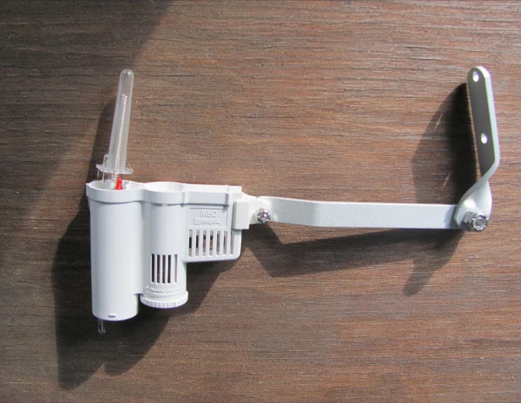
Click to zoom
Application Details
- Equipment Class
- DSC - Part 15 Security/Remote Control Transmitter
- Date of Grant
- Apr 22, 2010
- Application Purpose
- Original Equipment
- Date of Application
- Apr 22, 2010
- Equipment Note
- Wireless Solar Sync Transmitter
- Frequency Range
- 433.92000000 - 433.92000000
- Company
- Hunter Industries Inc
- Country
- United States
Documents & Files
Document Text
Text extracted from the exhibit documents filed with the FCC. Open a document above to read the original.
Users Manual
Wireless ET Sensor for Compatible Hunter Controllers Wireless ® Owner’s Manual and Programming Instructions for: • WSS: Wireless Solar Sync kit Pro-C, PCC, ICC, and I-Core controllers • WSSSEN: Wireless Solar Sync kit for ACC and X-Core controllers Table of ConTenTs InTrOduCTIOn................................................................................2 SySTEM OvErvIEW And OPErATIOn............................................2 SEnSOr dETAILS...............................................................................4 Installing.the.Sensor.......................................................................4 Clik.Operation................................................................................5 Bypassing.the.Sensor.....................................................................5 Maintaining.the.Sensor..................................................................5 COnnECTInG TO THE COnTrOLLEr..............................................6 Installing.and.Wiring.the.Module...................................................6 Pro-C.Conventional.Controller.(PCC.Series)..................................7 Pro-C.Controller.(PC.Series)...........................................................9 ICC.Controller..............................................................................10 I-Core.Controller..........................................................................11 X-Core.Controller.........................................................................12 ACC.Controller.............................................................................12 AddrESSInG WIrELESS rECEIvEr/SEnSOr................................13 PrOGrAMMInG COnTrOLLEr run TIMES..................................14 PrOGrAMMInG THE SOLAr SynC MOduLE...............................15 CALIbrATIOn / SETuP PErIOd......................................................18 TrOubLESHOOTInG GuIdE...........................................................19 SPECIFICATIOnS / dIMEnSIOnS / FCC nOTICE...........................20 Controller.Compatibility...............................................................20 Specifications...............................................................................20 Dimensions...................................................................................20 FCC.Notice...................................................................................21 Industry.of.Canada.Notice...........................................................22 CE.and.Australia.Notice...............................................................22 2 sysTem overvieW and operaTion The.Wireless.Solar.Sync.System.is.simply.and.easily.installed.on.any.compatible.Hunter.Irrigation.controller.(see.Owner’s.Manual.to.verify. compatibility)..The.Wireless.Solar.Sync.Sensor.measures.solar.radiation.and.temperature.and.calculates.the.daily.evapotranspiration.(ET). factor.for.irrigation..This.represents.the.amount.of.water.lost.by.the.plants.due.to.local.climate.conditions,.which.needs.to.be.replaced.by. irrigation..The.Wireless.Solar.Sync.also.includes.Hunter.Rain-Clik™.and.Freeze-Clik ® .sensors.that.will.automatically.shut.down.the.irrigation. system.during.rain.events.or.freezing.conditions. Enter.a.mid.summer.watering.program.in.your.controller.per.the.programming.instructions.in.the.Owner’s.Manual.provided.with.your. controller..The.Wireless.Solar.Sync.Sensor.sends.weather.data.and.applies.it.daily.to.the.controller’s.water.schedule.by.adjusting.the. controller.through.the.seasonal.adjust.feature. This.Owner’s.Manual.applies.to.the.following.kits: •..WSS:.Wireless.Solar.Sync.kit.for.Hunter.Pro-C,.PCC,.ICC,.and.I-Core.controllers... •..WSSSEN*:.Wireless.Solar.Sync.kit.for.Hunter.ACC.and.X-Core.controllers. *.Note.that.WSSSEN.does not.include.the.Solar.Sync.Module..The.ACC.and.X-Core.controllers.have.the.Solar.Sync.software.built.in.and.do. not.require.the.Solar.Sync.Module..Therefore,.the.WSSSEN.should.be.used.with.the.ACC.and.X-Core.Controllers. The.Solar.Sync.is.a.sensor.system.that,.when.connected.to.a. compatible.Hunter.controller,.will.automatically.adjust.your. controller.watering.based.upon.changes.in.local.climate.conditions.. The.Solar.Sync.utilizes.a.solar.and.temperature.sensor.to.measure. on-site.weather.conditions.used.to.determine.evapotranspiration. (ET),.or.the.rate.at.which.plants.and.turf.use.water..In.addition,.Solar. Sync.includes.a.Hunter.Rain-Clik™.and.Freeze-Clik™.sensor.that. will.shut.down.your.irrigation.system.when.it.rains.and/or.during. freezing.conditions.. inTroduCTion A.small.module.connects.the.sensor.to.the.controller.and.will. automatically.increase.or.decrease.watering.run.times.based.on. changes.in.weather..The.result.is.a.new.water-efficient.irrigation. product.that.promotes.water.conservation.and.healthier.plants... You.simply.program.your.controller.like.you.normally.would,.and.. the.Solar.Sync.takes.over.from.there,.eliminating.the.need.to. manually.adjust.your.watering.schedule. 3 sysTem overvieW and operaTion ® solar sync moduleWall mount bracket Wireless solar sync receiver Wireless solar sync sensor 4 sensor deTails installing the sensor Using.the.screws.provided,.mount.the.Solar.Sync.sensor.on.any. surface.where.it.will.be.exposed.to.unobstructed.sun.and.rainfall,. but.not.in.the.path.of.sprinkler.spray..The.sensor.needs.to.be. oriented.upright.and.the.swivel.bracket.can.be.moved.for.mounting. on.angled.surfaces..Loosen.the.locknut.and.screw.before.swiveling. the.bracket.and.then.retighten.. note: The Wireless Solar Sync Sensor is designed to operate to a maximum distance of 800 feet (228 m) from the Wireless receiver. note: Place Solar Sync where it can receive full sun. The.Sensor.Gutter.Mount.can.also.be.used.as.an.optional.mounting. method..The.Sensor.Gutter.Mount.(SGM).allows.the.Sensor.to.be. mounted.directly.to.the.edge.of.a.gutter..Install.the.SGM.on.the. Sensor.by.removing.the.extension.arm.supplied.with.your.Sensor. and.reinstalling.…
Text truncated - open the document above for the full version.
Attestation Statements
1 March 22, 2010 Compatible Electronics TCB 114 Olinda Drive Brea, California 92823 Subject: TCB application submittal Gentlemen: We, Hunter Industries, would like to declare that the application being submitted for the device with FCC ID: M3USSW, has not been submitted to another TCB for certification. The application was submitted to Compatible Electronics TCB on March 22,2010 If you have any questions, please do not hesitate to contact us at 760-591-7160. Sincerely, Peter Woytowitz Engineering Manager Hunter Industries, Inc
Cover Letter(s)
1 3/15/2010 Compatible Electronics TCB 114 Olinda Drive Brea, California 92823 Subject: Request for withholding from public disclosure the schematics, block diagrams, and operational description pursuant to an application for certification Gentlemen: We, Hunter Industries Inc., would like to request that all schematics, block diagrams, and operational descriptions submitted with the application for certification be withheld from public disclosure as per Section 0.459 of FCC Rules. This request is made under the provisions of Section 0.457 (d) of the Commission’s Rules, and Section 552 (b)(4) of the Freedom of Information Act. These sections authorize the withholding from public inspection, those materials which would be privileged as a matter of law if retained by the person submitting them, and materials which would not customarily be released to the public by that person. If you have any questions, please do not hesitate to contact us at 760-591-7160 Sincerely, Peter Woytowitz Engineering Manager Hunter Industries Inc.
Cover Letter(s)
1 Scott McCutchan From: Scott McCutchan [[email protected]] Sent: Wednesday, April 21, 2010 7:01 PM To: '[email protected]' Cc: '[email protected]'; '[email protected]' Subject: FCC ID: M3USSW Mr. Fujimoto: In order for processing of this certification application (FCC ID: M3USSW) to continue, the following issue(s) will have to be addressed: 1) Please provide appropriate justification for not displaying the two-condition statement required by section 15.31(a)(3) of the FCC rules on the device label 2) The operational description indicates that transmissions are automatically activated; however, the test report makes reference to a button, which would infer manual operation. Please clarify. The item(s) indicated above must be submitted before processing can continue on the above referenced application. Failure to provide the requested information within 60 days of the original e-mail date may result in application dismissal and forfeiture of the filing fee. Also, please note that partial responses increase processing time and should not be submitted. Please upload responses and/or exhibits to the electronic filing website. Your correspondence number is FCC ID: M3USSW -1. Best regards, Scott McCutchan Operations Manager Compatible Electronics TCB
Cover Letter(s)
Correspondence by Project Project Number: -1749327349 Correspondence Number Memo M3USSW-1 1. An Extra Photo has been uploaded to show the size of the chassis. 2. The test report has been revised to correctly state that the transmitter is manually activated.
Test Report
Plot Showing the Pulse Train Only Shows up Once per 100 mS Period Plot Showing Number of Pulses Time of Pulses 1-4, 6-7, 9-12, 14-18, 19-20, 22-24, 26-27, 31, 33-34, 37-39, and 42 = 190 uS Time of Pulse 5 = 310 uS Time of Pulse 8, 30, and 35 = 400 uS Time of Pulses 13 and 41 = 280 uS Time of Pulse 18 = 500 uS Time of Pulse 21 and 32 = 500 uS Time of Pulse 25 = 520 uS Time of Pulse 28 = 220 uS Time of Pulses 29 and 36 = 300 uS Time of Pulse 40 = 260 uS PULSE TIME OF PULSE (uS) 1 190 2 190 3 190 4 190 5 310 6 190 7 190 8 400 9 190 10 190 11 190 12 190 13 280 14 190 15 190 16 190 17 190 18 500 19 190 20 190 21 500 22 190 23 190 24 190 25 520 26 190 27 190 28 220 29 300 30 400 PULSE TIME OF PULSE (uS) 31 190 32 500 33 190 34 190 35 400 36 300 37 190 38 190 39 190 40 260 41 280 42 190 Total 10490 Total Duty Cycle 10.49%
Contact Information
Applicant
Satoshi Kuwahara(Director, Product Integrity)
Technical Contact
Compatible Electronics, Inc.Kyle Fujimoto
[email protected]714-579-0500
114 Olinda Drive · Brea, California · United States
Test Firm
Compatible Electronics, Inc.Michael Christensen
Technical Specifications
| # | Rule Parts | Frequency Range | Power Output |
|---|---|---|---|
| 1 | 15.231 | 433.92 MHz - 433.92 MHz | - |
Other Applications from Hunter Industries Inc
M3URMLR
May 21, 2026Remote
Equipment Class
DTS - Digital Transmission System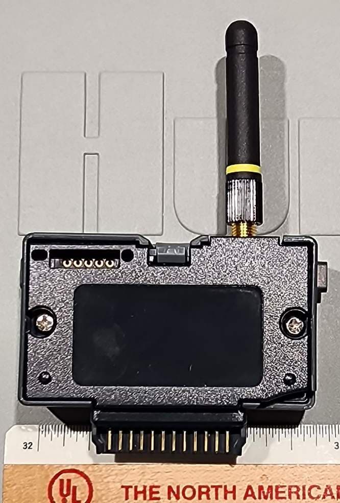
M3UA2CLORA
Apr 28, 2026LoRa Radio Module
Equipment Class
DTS - Digital Transmission System
M3U-WVL
Aug 18, 2024Wireless Valve Link
Equipment Class
DTS - Digital Transmission System
M3U-WVOM
Aug 18, 2024Quick plug-in controller
Equipment Class
DTS - Digital Transmission System
M3U-RPT
Aug 06, 2024Repeater
Equipment Class
DTS - Digital Transmission System