M3UWSSTXWireless Rain-Clik Transmitter
Hunter Industries Inc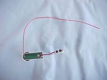
Click to zoom
Application Details
- Equipment Class
- DSC - Part 15 Security/Remote Control Transmitter
- Date of Grant
- Feb 05, 2004
- Application Purpose
- Original Equipment
- Date of Application
- Feb 05, 2004
- Equipment Note
- Wireless Rain-Clik Transmitter
- Frequency Range
- 315.00000000 - 315.00000000
- Company
- Hunter Industries Inc
- Country
- United States
Documents & Files
Document Text
Text extracted from the exhibit documents filed with the FCC. Open a document above to read the original.
Users Manual
Wireless Rain-Clik ™ Rain Sensors Installation Instructions INTRODUCTION The Wireless Rain-Clik™ acts as a switch to break the circuit to the solenoid valves of the irrigation system when it has rained. This allows the timer to advance as scheduled, but keeps the valves from opening the water flow. Once the Wireless Rain-Clik has dried sufficiently, the switch closes again to allow for normal operation. The Wireless Rain/Freeze-Clik ® includes a freeze sensor that is designed to keep the system from operating at, or below 3°C (37°F). At temperatures above 3°C, it will close the circuit for normal sprinker operation. CONTENTS Included with the Wireless Rain-Clik are the following items: 1. Sensor body with Transmitter 2. Telescoping extension arm 3. Wall mount / Conduit adapter 4. Gutter clip 5. Mounting Hardware 6. Receiver 7. Cover for Receiver MOUNTING Standard Mount: Using the screws provided, mount the Wireless Rain-Clik transmitter on any surface where it will be exposed to unobstructed rainfall, but not in the path of sprinkler spray. The switch-housing portion must be upright (as pictured), but the swivel-bracket can be moved for mounting on any angled surface. Gutter Mount: Clip the enclosed gutter mounting bracket over the inside lip of the gutter. Attach the Wireless Rain-Clik to the gutter mounting bracket with the screws provided. Helpful Hints for Mounting: A. Choose a location such as on the side of a building or post, the closer the Wireless Rain-Clik is to the controller, the better reception will be. DO NOT EXCEED 300 feet. B. Correct placement of the Wireless Rain/Freeze-Clik is important for accurate temperature sensing. The best location for mounting would be out of direct sunlight. C. As described in the “Operation” section of this manual, “reset rate” refers to the amount of time it takes the Wireless Rain-Clik to dry out sufficiently for the sprinkler system to be allowed to come back on. Mounting the Wireless Rain-Clik on a very sunny, southern end of a building may cause the Wireless Rain-Clik to dry out sooner than desired. Similarly, mounting on the northern end of a building with constant shade may keep the Wireless Rain-Clik from drying soon enough. Transmitters/Sensor • Nothing to set up with this unit after installation • The unit can be tested stand-alone as follows: press and hold the post on the quick response section. Within 3 seconds of pressing and holding this post down, the LED protruding from the potting should blink once. Release the post, within 3 seconds the LED should blink once again. (Figure 1) Receiver • Using the hardware included, mount the receiver to the wall (use included wall anchors if needed). Make sure to put the rubber cover/gasket under the unit when attaching it in an outdoor location. WIRING TO YOUR IRRIGATION SYSTEM WARNING! This unit is designed to be installed in conjunction with 24VAC circuits only. Do not use with 110 or 220VAC circuits. Receiver Installation, SRC Controller: (See Figure 2) 1. Attach the two yellow wires to the AC terminals of the SRC (polarity does not matter). 2. Attach the blue wire to the RS terminal. 3. Attach the white wire to the “C” terminal. 4. Attach the valve common wire to the RS terminal. Receiver Installation, Pro-C and ICC Controllers: (See Figure 3) 1. Attach the two yellow wires to the AC terminals of the controller (polarity does not matter). 2. Attach the blue wire to one SEN terminal and the white wire to the other SEN terminal of the controller. Receiver Installation, Other Controllers: A. Normally Closed Sensor Applications (See Figure 4) 1. Attach the two yellow wires to the AC terminals of the controllers (polarity does not matter). 2. To attach the receiver to this type of controller, attach the blue wire and the white wire to the sensor terminals of the controller, or in-line with the valve common. B. Normally Open Sensor Applications 1. A few controllers on the market require a normally open rain sensor. To attach the receiver to this type of controller, attach the blue wire and the orange wire to the controller’s sensor input. Gutter Mount Standard Mount Figure 1 Manually depress the spindle at the top of the Wireless Rain-Clik Wireless Rain Sensor Hunter SRC Figure 2 RRSC1ACAC23 W B Y Y Common Wire to all Valves Red light indicates sensor is bypassed GREEN = Sensor is dr y RED = Sensor is wet SENSOR BYPASS SENSOR STA TUS WIRELESS RAIN SENSOR RAIN SENSOR Press to bypass, press again to re-enabl e Figure 3 Wireless Rain Sensor Hunter ICC/Pro-C SEN SEN C TEST P MV AC AC G REM Red light indicates sensor is bypassed GREEN = Sensor is dr y RED = Sensor is wet SENSOR BYPASS SENSOR STA TUS WIRELESS RAIN SENSOR RAIN SENSOR Press to bypass, press again to re-enabl e B W Y Y Other Controllers Figure 4 P MVC Wireless Rain Sensor ACAC W B Y Y O Common Wire to all Valves Used for normally open sensor applications Red light indicates sensor is bypassed GREEN = Sensor is dr y RED = Sensor is wet SENSOR BYPASS SENSOR STA TUS WIRELESS RAIN SENSOR RAIN SENSOR Press to bypass, press again to re-enable ➀ ➂ ➃ ➄ ➁ Red light indicates sensor is bypassed GREEN = Sensor is dr y RED = Sensor is wet SENSOR BYPASS SENSOR STATUS WIRELESS RAIN SENSOR RAIN SENSOR Press to bypass, press again to re-enable ➆➅ Wireless Rain-Clik ™ Rain Sensors Installation Instructions Hunter Industries Incorporated • The Irrigation Innovators © 2004 Hunter Industries Incorporated www.HunterIndustries.com 23-461 2/04 Receiver Installation, Other Controllers (continued): C. 24 Volt Solenoid Valves with Booster Pump (See Figure 5) Locate the common wire to the solenoid valves and the common wire leading to the coil of the relay that starts the pump. If these two wires are connected to the “common” terminal on the controller, disconnect both of them. Twist together these two wires along with one wire from the Rain-Clik™, and secure with a wire nut. Attach the other wire of the Wireless Rain-Clik™ receiver to the “common” terminal on…
Text truncated - open the document above for the full version.
ID Label/Location Info
FCCID: M3UWSSTX IC: XXXX-XXXXX Made in China Location of Label:
Test Report
Report Number: B31223A1 FCC Part 15 Subpart B and FCC Section 15.231 Test Report Wireless Rain-Clik Transmitter Model: WRFC-TR Brea Division 114 Olinda Drive Brea, CA 92823 (714) 579-0500 Agoura Division 2337 Troutdale Drive Agoura, CA 91301 (818) 597-0600 Silverado Division 19121 El Toro Road Silverado, CA 92676 (949) 589-0700 Lake Forest Division 20621 Pascal Way Lake Forest, CA 92630 (949) 587-0400 Page 1 of 15 FCC PART 15, SUBPART B and C TEST REPORT for WIRELESS RAIN-CLIK TRANSMITTER MODEL: WRFC-TR Prepared for HUNTER INDUSTRIES INCORPORATED 1940 DIAMOND STREET SAN MARCOS, CA 92069 Prepared by:_____________________ MICHAEL CHRISTENSEN Approved by:____________________ KYLE FUJIMOTO COMPATIBLE ELECTRONICS INC. 114 OLINDA DRIVE BREA, CALIFORNIA 92823 (714) 579-0500 DATE: JANUARY 6, 2004 REPORT APPENDICES TOTAL BODY A B C D E PAGES 15 2 2 2 10 16 47 This report shall not be reproduced except in full, without the written approval of Compatible Electronics. Report Number: B31223A1 FCC Part 15 Subpart B and FCC Section 15.231 Test Report Wireless Rain-Clik Transmitter Model: WRFC-TR Brea Division 114 Olinda Drive Brea, CA 92823 (714) 579-0500 Agoura Division 2337 Troutdale Drive Agoura, CA 91301 (818) 597-0600 Silverado Division 19121 El Toro Road Silverado, CA 92676 (949) 589-0700 Lake Forest Division 20621 Pascal Way Lake Forest, CA 92630 (949) 587-0400 Page 2 of 15 TABLE OF CONTENTS Section / Title PAGE GENERAL REPORT SUMMARY 4 SUMMARY OF TEST RESULTS 4 1. PURPOSE 5 2. ADMINISTRATIVE DATA 6 2.1 Location of Testing 6 2.2 Traceability Statement 6 2.3 Cognizant Personnel 6 2.4 Date Test Sample was Received 6 2.5 Disposition of the Test Sample 6 2.6 Abbreviations and Acronyms 6 3. APPLICABLE DOCUMENTS 7 4. DESCRIPTION OF TEST CONFIGURATION 8 4.1 Description Of Test Configuration - EMI 8 4.1.1 Cable Construction and Termination 9 5. LISTS OF EUT, ACCESSORIES AND TEST EQUIPMENT 10 5.1 EUT and Accessory List 10 5.2 EMI Test Equipment 11 6. TEST SITE DESCRIPTION 12 6.1 Test Facility Description 12 6.2 EUT Mounting, Bonding and Grounding 12 7. TEST PROCEDURES 13 7.1 Radiated Emissions (Spurious and Harmonics) Test 13 7.2 Bandwidth of the Fundamental 14 8. CONCLUSIONS 15 Report Number: B31223A1 FCC Part 15 Subpart B and FCC Section 15.231 Test Report Wireless Rain-Clik Transmitter Model: WRFC-TR Brea Division 114 Olinda Drive Brea, CA 92823 (714) 579-0500 Agoura Division 2337 Troutdale Drive Agoura, CA 91301 (818) 597-0600 Silverado Division 19121 El Toro Road Silverado, CA 92676 (949) 589-0700 Lake Forest Division 20621 Pascal Way Lake Forest, CA 92630 (949) 587-0400 Page 3 of 15 LIST OF APPENDICES APPENDIX TITLE A Laboratory Recognitions B Modifications to the EUT C Additional Models Covered Under This Report D Diagrams, Charts, and Photos • Test Setup Diagrams • Radiated Emissions Photos • Antenna and Effective Gain Factors E Data Sheets LIST OF FIGURES FIGURE TITLE 1 Plot Map And Layout of Radiated Site Report Number: B31223A1 FCC Part 15 Subpart B and FCC Section 15.231 Test Report Wireless Rain-Clik Transmitter Model: WRFC-TR Brea Division 114 Olinda Drive Brea, CA 92823 (714) 579-0500 Agoura Division 2337 Troutdale Drive Agoura, CA 91301 (818) 597-0600 Silverado Division 19121 El Toro Road Silverado, CA 92676 (949) 589-0700 Lake Forest Division 20621 Pascal Way Lake Forest, CA 92630 (949) 587-0400 Page 4 of 15 GENERAL REPORT SUMMARY This electromagnetic emission test report is generated by Compatible Electronics Inc., which is an independent testing and consulting firm. The test report is based on testing performed by Compatible Electronics personnel according to the measurement procedures described in the test specifications given below and in the "Test Procedures" section of this report. The measurement data and conclusions appearing herein relate only to the sample tested and this report may not be reproduced without the written permission of Compatible Electronics, unless done so in full. This report must not be used to claim product endorsement by NVLAP, NIST or any other agency of the U.S. Government. Device Tested: Wireless Rain-Clik Transmitter Model: WRFC-TR S/N: N/A Product Description: See Expository Statement Modifications: The EUT was not modified in order to meet the specifications. Manufacturer: Hunter Industries Incorporated 1940 Diamond Street San Marcos, CA 92069 Test Dates: December 22 and 23, 2003 Test Specifications : EMI requirements CFR Title 47, Part 15 Subpart B; and Subpart C, Sections 15.205, 15.209 and 15.231 Test Procedure: ANSI C63.4: 2001 Test Deviations: The test procedure was not deviated from during the testing. SUMMARY OF TEST RESULTS TEST DESCRIPTION RESULTS 1 Conducted RF Emissions, 150 kHz - 30 MHz This test was not performed because the EUT operates on DC power only and cannot be plugged into the AC public mains. 2 Radiated RF Emissions, 10 kHz - 3150 MHz Complies with the Class B limits of CFR Title 47, Part 15, Subpart B; and Subpart C, sections 15.205, 15.209, and 15.231. Report Number: B31223A1 FCC Part 15 Subpart B and FCC Section 15.231 Test Report Wireless Rain-Clik Transmitter Model: WRFC-TR Brea Division 114 Olinda Drive Brea, CA 92823 (714) 579-0500 Agoura Division 2337 Troutdale Drive Agoura, CA 91301 (818) 597-0600 Silverado Division 19121 El Toro Road Silverado, CA 92676 (949) 589-0700 Lake Forest Division 20621 Pascal Way Lake Forest, CA 92630 (949) 587-0400 Page 5 of 15 1. PURPOSE This document is a qualification test report based on the Electromagnetic Interference (EMI) tests performed on the Wireless Rain-Clik Transmitter Model: WRFC-TR. The EMI measurements were performed according to the measurement procedure described in ANSI C63.4: 2001. The tests were performed in order to determine whether the electromagnetic emissions from the equipment under test, referred to as EUT hereafter, are within the Class B specification limits defined by CFR Title 47, Part 15, Subpart B; and Subpart C, sections 15.205, 15.209, and 15.231. Report Num…
Text truncated - open the document above for the full version.
Contact Information
Applicant
Satoshi Kuwahara(Director, Product Integrity)
Technical Contact
Compatible ElectronicsMichael P Christensen
[email protected]714-579-0500
114 Olinda Drive · Brea, California · United States
Test Firm
Compatible ElectronicsScott McCutchan
714-579-0500Fax: 714-579-1850
Technical Specifications
| # | Rule Parts | Frequency Range | Power Output |
|---|---|---|---|
| 1 | 15.231 | 315 MHz - 315 MHz | - |
Other Applications from Hunter Industries Inc
M3URMLR
May 21, 2026Remote
Equipment Class
DTS - Digital Transmission System
M3UA2CLORA
Apr 28, 2026LoRa Radio Module
Equipment Class
DTS - Digital Transmission System
M3U-WVL
Aug 18, 2024Wireless Valve Link
Equipment Class
DTS - Digital Transmission System
M3U-WVOM
Aug 18, 2024Quick plug-in controller
Equipment Class
DTS - Digital Transmission System
M3U-RPT
Aug 06, 2024Repeater
Equipment Class
DTS - Digital Transmission System