M3UWVCWireless Valve Controller
Hunter Industries Inc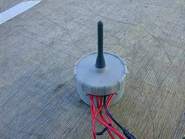
Click to zoom
Application Details
- Equipment Class
- DXT - Part 15 Low Power Transceiver, Rx Verified
- Date of Grant
- Mar 02, 2003
- Application Purpose
- Original Equipment
- Date of Application
- Mar 02, 2003
- Equipment Note
- Wireless Valve Controller
- Frequency Range
- 921.75000000 - 921.75000000
- Company
- Hunter Industries Inc
- Country
- United States
Documents & Files
Document Text
Text extracted from the exhibit documents filed with the FCC. Open a document above to read the original.
Users Manual
® WVC Wireless Valve Controller Multiple Station Battery Powered Irrigation Controller Owner’s Manual and Installation Instructions Introduction...................................................................................................................................................................1 WVC Components...........................................................................................................................................................2 Installing the Battery......................................................................................................................................................3 Wiring DC Latching Solenoids to the WVC.......................................................................................................................4 Radio Communication.....................................................................................................................................................5 Addressing the WVC with the WVP..................................................................................................................................6 Mounting the WVC to a Hunter Valve...............................................................................................................................7 Alternate Mounting Methods...........................................................................................................................................8 Connecting a Weather Sensor.........................................................................................................................................9 Programming the Controller............................................................................................................................................9 Specifications...............................................................................................................................................................10 FCC Notice...................................................................................................................................................................11 Industry of Canada Notice.............................................................................................................................................12 CE Notice.....................................................................................................................................................................12 TABLE OF CONTENTS..................................................................................... 1 The Hunter Wireless Valve Controller (WVC) is a battery-powered, radio programmable controller that can operate up to two (WVC-200) or four valves (WVC-400). Hunter’s Wireless Battery powered irrigation systems are ideal for commercial/ municipal applications such as street and highway landscaping, medians, parks, construction sites, and other areas that do not have access to power. All programming and manual operations with the WVC are accomplished with the Wireless Valve Programmer (WVP). The WVP is a hand-held programmer that allows you to create programs and conduct manual operations with WVC controllers in the field. Because the WVP retrieves and transmits data via radio signals, you never have to open a valve box to check the status or program your controllers. The following instructions provide information on installing and setting up your WVC. Additional programming instructions can be found in the WVP Owner’s Manual. INTRODUCTION............................................................................................... 2 WVC COMPONENTS........................................................................................ This section provides a brief overview of some of the com- ponents of the WVC. Each item will be discussed in further detail later, however, this section can be helpful in getting acquainted with the different options available. 1. WVC Body – The WVC controller is designed to be dirt tolerant, waterproof, and submersible to 12 feet. 2. External Antennae – Flexible rubber antennae for radio communication. 3. 9-Volt Battery Holder – The WVC is designed to oper- ate on a single 9-volt alkaline battery. The battery easily snaps into the battery holder. 4. Wires for DC Latching Solenoids – Leads are provided for wiring DC latching solenoids. The red wires are numbered on top of the WVC to provide station identifi- cation. The black wire is the common wire. 5. Weather Sensor Wires – A Hunter Mini-Clik ® or other micro-switch type sensor can be connected to the WVC. 6. Valve Mounting Clip – Allows the WVC to be mounted directly to any Hunter valve. The clip can also be used in conjunction with the Universal Mounting Adapter. 7. Universal Mounting Adapter – Allows for alternate methods of mounting the WVC. It can be used to mount the WVC to the side of the valve box or on a 1⁄2" (13 mm) diameter section of plastic pipe. 8. LED Indicator Light – Used when setting the WVC address. 3 The WVC uses a standard 9-volt alkaline battery to operate the valve and program the controller. Battery life is affected by the number of valve actuations, along with the distance the solenoids are from the controller. Under normal service conditions the battery should provide at least one full year of service. NOTE: The WVC has non-volatile memory that retains all program information when the battery is removed or in the event the battery is drained. To install the battery: 1. Unscrew the rear half of the WVC body to gain access to the battery compartment. INSTALLING THE BATTERY........................................................................... 2. Snap the battery into the battery holder. NOTE: The battery holder is designed so that the battery can only be inserted in one direction. 3. Make sure no water is inside the battery compartment. Make sure that the seals are in good condition. Screw the WVC body halves toge…
Text truncated - open the document above for the full version.
ID Label/Location Info
M a d e i n C h i n a WVP FCC ID: M3UWVC IC: 2772-WVC This device complies with part 15 of the FCC Rules. Operation is subject to the following two conditions: 1. This device may not cause harmful interference and 2. this device must accept any interference received, including interference that may cause undesired operation N10675
Test Report
Report Number: B21218D1 FCC Part 15 Subpart B and FCC Section 15.249 Test Report Wireless Valve Controller Model: WVC-XXX 114 OLINDA DRIVE, BREA, CALIFORNIA 92823 PHONE: (714) 579-0500 FAX: (714) 579-1850 Page 1 of 15 FCC PART 15, SUBPART B and C TEST REPORT for WIRELESS VALVE CONTROLLER MODEL: WVC-XXX Prepared for HUNTER INDUSTRIES, INC. 1940 DIAMOND STREET SAN MARCOS, CALIFORNIA 92069 Prepared by:_____________________ KYLE FUJIMOTO Approved by:____________________ MICHAEL CHRISTENSEN COMPATIBLE ELECTRONICS INC. 114 OLINDA DRIVE BREA, CALIFORNIA 92823 (714) 579-0500 DATE: JANUARY 31, 2003 REPORT APPENDICES TOTAL BODY A B C D E PAGES 15 2 2 2 10 12 43 This report shall not be reproduced except in full, without the written approval of Compatible Electronics. Report Number: B21218D1 FCC Part 15 Subpart B and FCC Section 15.249 Test Report Wireless Valve Controller Model: WVC-XXX 114 OLINDA DRIVE, BREA, CALIFORNIA 92823 PHONE: (714) 579-0500 FAX: (714) 579-1850 Page 2 of 15 TABLE OF CONTENTS Section / Title PAGE GENERAL REPORT SUMMARY 4 SUMMARY OF TEST RESULTS 4 1. PURPOSE 5 2. ADMINISTRATIVE DATA 6 2.1 Location of Testing 6 2.2 Traceability Statement 6 2.3 Cognizant Personnel 6 2.4 Date Test Sample was Received 6 2.5 Disposition of the Test Sample 6 2.6 Abbreviations and Acronyms 6 3. APPLICABLE DOCUMENTS 7 4. Description of Test Configuration 8 4.1 Description of Test Configuration - EMI 8 4.1.1 Cable Construction and Termination 9 5. LISTS OF EUT, ACCESSORIES AND TEST EQUIPMENT 10 5.1 EUT and Accessory List 10 5.2 EMI Test Equipment 11 6. TEST SITE DESCRIPTION 12 6.1 Test Facility Description 12 6.2 EUT Mounting, Bonding and Grounding 12 7. Test Procedures 13 7.1 Radiated Emissions (Spurious and Harmonics) Test 13 8. CONCLUSIONS 15 Report Number: B21218D1 FCC Part 15 Subpart B and FCC Section 15.249 Test Report Wireless Valve Controller Model: WVC-XXX 114 OLINDA DRIVE, BREA, CALIFORNIA 92823 PHONE: (714) 579-0500 FAX: (714) 579-1850 Page 3 of 15 LIST OF APPENDICES APPENDIX TITLE A Laboratory Recognitions B Modifications to the EUT C Additional Models Covered Under This Report D Diagrams, Charts, and Photos • Test Setup Diagrams • Radiated Emissions Photos • Antenna and Effective Gain Factors E Data Sheets LIST OF FIGURES FIGURE TITLE 1 Plot Map And Layout of Radiated Site Report Number: B21218D1 FCC Part 15 Subpart B and FCC Section 15.249 Test Report Wireless Valve Controller Model: WVC-XXX 114 OLINDA DRIVE, BREA, CALIFORNIA 92823 PHONE: (714) 579-0500 FAX: (714) 579-1850 Page 4 of 15 GENERAL REPORT SUMMARY This electromagnetic emission test report is generated by Compatible Electronics Inc., which is an independent testing and consulting firm. The test report is based on testing performed by Compatible Electronics personnel according to the measurement procedures described in the test specifications given below and in the "Test Procedures" section of this report. The measurement data and conclusions appearing herein relate only to the sample tested and this report may not be reproduced without the written permission of Compatible Electronics, unless done so in full. This report must not be used to claim product endorsement by NVLAP or any other agency of the U.S. Government. Device Tested: Wireless Valve Controller Model: WVC-XXX S/N: N/A Product Description: See Expository Statement. Modifications: The EUT was not modified during the testing. Manufacturer: Hunter Industries, Inc. 1940 Diamond Street San Marcos, California 92069 Test Date: December 18, 2002 Test Specifications : EMI requirements CFR Title 47, Part 15 Subpart B; and Subpart C, Sections 15.205, 15.209, and 15.249 Test Procedure: ANSI C63.4: 1992 Test Deviations: The test procedure was not deviated from during the testing. SUMMARY OF TEST RESULTS TEST DESCRIPTION RESULTS 1 Conducted RF Emissions, 450 kHz - 30 MHz This test was not performed because the EUT operates on a nine volt battery only and cannot be plugged into the AC public mains. 2 Radiated RF Emissions, 10 kHz - 9300 MHz Complies with the Class B limits of CFR Title 47, Part 15, Subpart B; and Subpart C, sections 15.205, 15.209, and 15.249. Report Number: B21218D1 FCC Part 15 Subpart B and FCC Section 15.249 Test Report Wireless Valve Controller Model: WVC-XXX 114 OLINDA DRIVE, BREA, CALIFORNIA 92823 PHONE: (714) 579-0500 FAX: (714) 579-1850 Page 5 of 15 1. PURPOSE This document is a qualification test report based on the Electromagnetic Interference (EMI) tests performed on the Wireless Valve Controller Model: WVC-XXX. The EMI measurements were performed according to the measurement procedure described in ANSI C63.4: 1992. The tests were performed in order to determine whether the electromagnetic emissions from the equipment under test, referred to as EUT hereafter, are within the Class B specification limits defined by CFR Title 47, Part 15, Subpart B; and Subpart C, sections 15.205, 15.209, and 15.249. Report Number: B21218D1 FCC Part 15 Subpart B and FCC Section 15.249 Test Report Wireless Valve Controller Model: WVC-XXX 114 OLINDA DRIVE, BREA, CALIFORNIA 92823 PHONE: (714) 579-0500 FAX: (714) 579-1850 Page 6 of 15 2. ADMINISTRATIVE DATA 2.1 Location of Testing The EMI tests described herein were performed at the test facility of Compatible Electronics, 114 Olinda Drive, Brea, California 92823. 2.2 Traceability Statement The calibration certificates of all test equipment used during the test are on file at the location of the test. The calibration is traceable to the National Institute of Standards and Technology (NIST) . 2.3 Cognizant Personnel Hunter Industries, Inc. Tom Kadien Senior Electrical Engineer Peter Woytowitz Engineering Manager Compatible Electronics, Inc. Kyle Fujimoto Test Engineer Kirit Ramani Test Engineer Michael Christensen Test Engineer 2.4 Date Test Sample was Received The test sample was received on December 15, 2002. 2.5 Disposition of the Test Sample The sample was returned to Hunter Industries, Inc. on January 15, 2003. 2.6 Abbrevi…
Text truncated - open the document above for the full version.
Contact Information
Applicant
Satoshi Kuwahara(Director, Product Integrity)
Technical Contact
Compatible ElectronicsKyle Fujimoto
[email protected]714-579-0500
114 Olinda Drive · Brea, California · United States
Test Firm
Compatible ElectronicsScott McCutchan
714-579-0500Fax: 714-579-1850
Technical Specifications
| # | Rule Parts | Frequency Range | Power Output |
|---|---|---|---|
| 1 | 15C | 921.75 MHz - 921.75 MHz | - |
Other Applications from Hunter Industries Inc
M3URMLR
May 21, 2026Remote
Equipment Class
DTS - Digital Transmission System
M3UA2CLORA
Apr 28, 2026LoRa Radio Module
Equipment Class
DTS - Digital Transmission System
M3U-WVL
Aug 18, 2024Wireless Valve Link
Equipment Class
DTS - Digital Transmission System
M3U-WVOM
Aug 18, 2024Quick plug-in controller
Equipment Class
DTS - Digital Transmission System
M3U-RPT
Aug 06, 2024Repeater
Equipment Class
DTS - Digital Transmission System