M4Y-000325PCMCIA Wireless LAN Card
Z Com Inc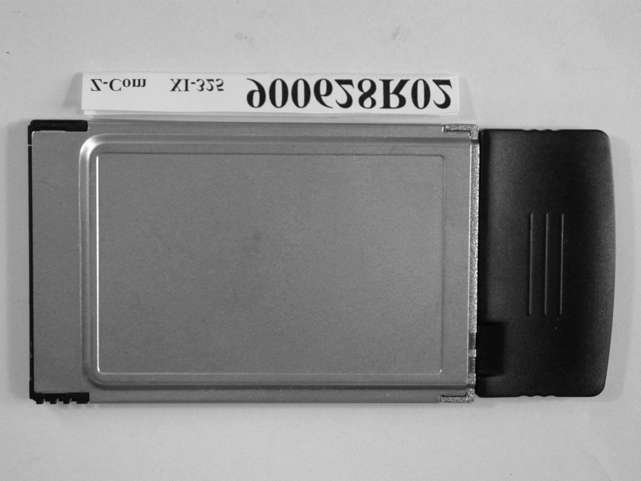
Click to zoom
Application Details
- Equipment Class
- DSS - Part 15 Spread Spectrum Transmitter
- Date of Grant
- Aug 19, 2001
- Application Purpose
- Original Equipment
- Date of Application
- Aug 19, 2001
- Equipment Note
- PCMCIA Wireless LAN Card
- Frequency Range
- 2412.00000000 - 2462.00000000
- Company
- Z Com Inc
- Country
- Taiwan
Documents & Files
Document Text
Text extracted from the exhibit documents filed with the FCC. Open a document above to read the original.
Users Manual
Z-Com, Inc. 1 7F-2, 9, Prosperity 1st Rd., Science-Based Industrial Park, Hsinchu, Taiwan Tel: +886-3-577-7364 Fax: +886-3-577-3359 Website: http:/// www.zcom.com.tw Email: info@ zcom.com.tw XI-325/B Quick Installation Guide I. Network Configuration XI-325/B is an IEEE802.11/802.11b-compliant PCMCIA Type II DSSS wireless LAN PC card. It fully supports wireless networking under Windows 95/98, and NT 4.0. ® XI-325/B can be operated in Ad-Hoc and Infrastructure network configurations. Ad-Hoc mode allows XI-325/B users to join an Basic Service Set (i.e., peer-to-peer mode, without access point). Infrastructure mode allows XI-325/B users to join a Extended Basic Service Set (i.e., connect to access point) II. Package Content XI-325/B 11Mb PC x 1 CD-ROM or Driver and Utility Disk x 1 XI-325/B Detachable Antenna x 1 Quick Installation Guide x 1 III. XI-325/B and Utility Installation under Windows 95/98 1. Insert XI-325/B into the PCMCIA slot, then start Windows. Windows will auto-detect new hardware and Windows Wizard will display “New Hardware Found” 2. Click on ‘Next’, then insert the corresponding driver and utility CD-ROM into the CD-ROM drive, or the driver and utility disk into the floppy drive. Click on ‘Next’. 3. Once [Insert Win 95/98 CD-Rom into the appropriate drive, then click ‘OK’] window appears, please follow by either inserting the Win 95/98 CD-Rom or finding the Win 95/98 source path within the appropriate drives, then click ‘OK’. 4. Click ‘Finish’ to complete the installation. Restart Win 95/98. 5. To install the XI-325/B Utility, insert the XI-325/B driver and utility disk once again, then execute A: setup.exe. 6. Follow the on-screen instructions to complete utility installation, then afterward double-click on Infrastructure Network Ad-hoc Network Wired Network Wireless Network Access Point Z-Com, Inc. 2 7F-2, 9, Prosperity 1st Rd., Science-Based Industrial Park, Hsinchu, Taiwan Tel: +886-3-577-7364 Fax: +886-3-577-3359 Website: http:/// www.zcom.com.tw Email: info@ zcom.com.tw the Utility icon. Utility interface will then appear and configuration can be accomplished here. IV. Using Utility to Set Up Ad-Hoc Network If wireless LAN has already been set up, simply plug in XI-325/B. Otherwise, set up a wireless network by taking the following steps: 1. On the main utility interface, click on [Diagnostic tools], then click on [Site Survey]. This would disable wireless network links temporarily and display channel quality on all 14 channels. Please note that the blue bars indicate quality channels. Select such channel in Step 2’s Ad-Hoc network channel selection. 2. Back on the main utility interface, click on [Network Configuration] and “Configure the Adapter” window will appear. Setup procedures are as follows: 1) ESSID denotes the assigned name for the designated wireless LAN. If ESSID differs, then wireless connection between wireless end devices will not be accomplished. Please note that selecting [Use Non-Specified ESSID: ANY] will possibly be connected to other wireless LAN. Therefore, ESSID setup is highly recommended. Example: Specify ESSID as : ZCOM001. Notice: Once the ESSID is set on the initial XI-325/B, and while the rest of the ESSID remains as default value ANY, then the initial XI-325/B with the ESSID must be started first. 2) Select [Ad-Hoc] under ‘Network Type’, select the Channel in step 1 for [Ad-Hoc Default Channel]. (Notice: Under Ad-Hoc, it would require a single uniform channel to enable a wireless networking group). 3) Use WEP ** (will be available soon). The default is ‘Disable’. If you require high security in transmission, please select the “Enable” item and select [Encryption]. When you enter encryption configuration, you can type keyword and press [Generate] to create 4 new encryption keys and select one of them to scramble your transmission data. Notice: When your use WEP to communicate with the other wireless clients, all the wireless devices in this network must have the same encryption key and keyword. 4) Upon completing steps 1~3, click on [Modify] to save altered values. V. Using Utility to set up Infrastructure Network 1. On the main Utility interface, click on [Diagnostic Tools], then click on [Access Point Browser]. This would disable wireless connection temporarily and the subsequent display Z-Com, Inc. 3 7F-2, 9, Prosperity 1st Rd., Science-Based Industrial Park, Hsinchu, Taiwan Tel: +886-3-577-7364 Fax: +886-3-577-3359 Website: http:/// www.zcom.com.tw Email: info@ zcom.com.tw would show status for all available access points. By using this tool, it is possible to find out ESSID for the connected wireless group.On the main Utility interface, click on [Network Configuration] and configuration screen will appear. Setup procedures are as follows: 1) ESSID denotes the assigned name for the designated wireless LAN. If ESSID differs, then wireless connection between wireless end devices will not be accomplished. Please note that selecting [Use Non-Specified ESSID: ANY] will possibly be connected to other wireless LAN with different ESSID. Therefore, ESSID setup is highly recommended. Example : Specify ESSID as : ZCOM001. Notice: If the ESSID of PC card remains as default value ANY, then the PC card is possible to be connected to all available Access Points. 2) Select [Infrastructure] under ‘Network Type’ 3) Use WEP ** (will be available soon). The default is ‘Disable’. If you require high security in transmission, please select the “Enable” item and select [Encryption]. When you enter encryption configuration. You can type keyword and press [Generate] to create 4 new encryption keys and select one of them to scramble your transmission data. Notice: When your use WEP to communicate with the other wireless clients, all the wireless devices in this network must have the same Encryption Key and keyword. ) 4) Upon completing steps 1~3, click on [Modify] to save altered values. l Infrastructure network configuration provides roaming to mobile users.…
Text truncated - open the document above for the full version.
External Photos
1 ANNEX PHOTOGRAPHS OF EUT 2 3 4
ID Label/Location Info
FCC ID: LABEL LOCATION
Internal Photos
5 6 7
Internal Photos
8 9
RF Exposure Info
FCC ID: M4Y-000325 ADT No.: 900628R02 FCC TEST REPORT REPORT NO.: RF900628R02 MODEL NO.: XI-325 XI-325B ACCORDING: FCC Guidelines for Human Exposure IEEE C95.1 APPLICANT:Z-COM, INC. ADDRESS: 7F-2, No.9, Prosperity RD.I, Science-Based Industrial Park, Hsinchu,300 Taiwan, R.O.C. ISSUED BY:Advance Data Technology Corporation LAB LOCATION:47 14th Lin, Chiapau Tsun, Linko, Taipei, Taiwan, R.O.C. 0528 Lab Code: 200102-0 FCC ID: M4Y-000325 ADT No.: 900628R02 RF Exposure Measurement (Mobile Device) 1. Introduction 2.4 GHz frequency band is regarded specially as a dangerous band for its heating harmfulness to the human body. Thatís why microwave oven is operating in this frequency band. The manufacturer whose product is working in this frequency band is obligatory to prove the harmfulness of his product. In this document, we try to prove the safety of radiation harmfulness to the human body for our product. The limit for Maximum Permissible Exposure (MPE) specified in FCC 1.1310 is followed. The Gain of the antenna used in this product is measured in a Fully Anechoic Chamber (FAC), and the maximum total power input to the antenna is measured. Through the Friis transmission formula and the maximum gain of the antenna, we can calculate the distance, away from the product, where the limit of MPE is reached. 2. Classification The antenna of the product, under normal use condition, is at least 20 cm away from the body of the user. Warning statement for keeping 20 cm separation distance and the prohibition of operating next to a person has been printed on the users manual. So, this product is classified as the Mobile Device. 3. RF Exposure Limit According to FCC 1.1310: The criteria listed in the following table shall be used to evaluate the environmental impact of human exposure to radio-frequency (RF) radiation as specified in 1.1307(b). FCC ID: M4Y-000325 ADT No.: 900628R02 LIMITS FOR MAXIMUM PERMISSIBLE EXPOSURE (MPE) Frequency Range (MHz) Electric Field Strength (V/m) Magnetic Field Strength (A/m) Power Density (mW/cm 2 ) Average Time (minutes) (A)Limits For Occupational / Control Exposures 30-30061.40.1631.06 300-1500ÖÖF/3006 1500-100,000ÖÖ56 (B)Limits For General Population / Uncontrolled Exposure 30-30027.50.0730.230 300-1500ÖÖF/150030 1500-100,000ÖÖ1.030 F = Frequency in MHz 4. Friis Formula Friis transmission formula : Pd = (Pout*G) / (4*pi*r 2 ) where Pd = power density in mW/cm 2 Pout = output power to antenna in mW G = gain of antenna in linear scale Pi = 3.1416 R = distance between observation point and center of the radiator in cm Pd is the limit of MPE, 1 mW/cm 2 . If we know the maximum Gain of the antenna and the total power input to the antenna, through the calculation, we will know the distance r where the MPE limit is reached. Ref. : David K. Cheng, Field and Wave Electromagnetics, Second Edition, Page 640, Eq. (11-133). 5. EUT Operating condition The software provided by Manufacturer enabled the EUT to transmit and receive data at lowest, middle and highest channel individually. FCC ID: M4Y-000325 ADT No.: 900628R02 6. Test Results 6.1 Antenna Gain The maximum Gain measured in Fully Anechoic Chamber is -1 dBi or 0.79 (numeric). 6.2 Output Power Into Antenna & RF Exposure Distance : CHANNEL CHANNEL FREQUENCY (MHz) OUTPUT POWER TO ANTENNA (mW) MINIMUM ALLOWABLE DISTANCE ( r ) FROM SKIN (Centi-Meter) 1241264.572.01 6243765.312.03 11246264.862.02 The minimum allowable distance is very close to the enclosure of the antenna and is very far away from the human being under normal use condition.
Test Report
FCC ID: M4Y-000325 Report No.: RF900628R02 1 Issued: August 13, 2001 FCC TEST REPORT REPORT NO.: RF900628R02 MODEL NO.: XI-325, XI-325B RECEIVED: June 28, 2001 TESTED: July 2 ~ August 9, 2001 APPLICANT: Z-COM, INC. ADDRESS: 7F-2, No.9, Prosperity RD. I, Science-Based Industrial Park Hsinchu, 300 Taiwan, R.O.C. ISSUED BY: Advance Data Technology Corporation LAB LOCATION: 47 14th Lin, Chiapau Tsun, Linko, Taipei, Taiwan, R.O.C. This test report consists of 62 pages in total. It may be duplicated completely for legal use with the approval of the applicant. It should not be reproduced except in full, without the written approval of our laboratory. The client should not use it to claim product endorsement by CNLA, NVLAP or any government agencies. The test results in the report only apply to the tested sample. 0528 Lab Code: 200102-0 FCC ID: M4Y-000325 Report No.: RF900628R02 2 Issued: August 13, 2001 Table of Contents 1CERTIFICATION ........................................................................................... 4 2SUMMARY OF TEST RESULTS ................................................................... 5 3GENERAL INFORMATION............................................................................ 6 3.1GENERAL DESCRIPTION OF EUT.............................................................. 6 3.2DESCRIPTION OF TEST MODES ................................................................ 7 3.3GENERAL DESCRIPTION OF APPLIED STANDARDS ............................... 7 3.4DESCRIPTION OF SUPPORT UNITS .......................................................... 8 4TEST TYPES AND RESULTS ....................................................................... 9 4.1CONDUCTED EMISSION MEASUREMENT ................................................ 9 4.1.1LIMITS OF CONDUCTED EMISSION MEASUREMENT .............................. 9 4.1.2TEST INSTRUMENTS................................................................................... 9 4.1.3TEST PROCEDURES ................................................................................. 10 4.1.4TEST SETUP .............................................................................................. 10 4.1.5EUT OPERATING CONDITIONS ................................................................ 11 4.1.6TEST RESULTS(A) ..................................................................................... 12 4.1.7TEST RESULTS(B) ..................................................................................... 18 4.2RADIATED EMISSION MEASUREMENT ................................................... 24 4.2.1LIMITS OF RADIATED EMISSION MEASUREMENT ................................. 24 4.2.2TEST INSTRUMENTS................................................................................. 25 4.2.3TEST PROCEDURES ................................................................................. 26 4.2.4TEST SETUP .............................................................................................. 27 4.2.5EUT OPERATING CONDITIONS ................................................................ 27 4.2.6TEST RESULTS(A) ..................................................................................... 28 4.2.7TEST RESULTS(B) ..................................................................................... 33 4.36DB BANDWIDTH MEASUREMENT .......................................................... 38 4.3.1LIMITS OF 6dB BANDWIDTH MEASUREMENT ........................................ 38 4.3.2TEST INSTRUMENTS................................................................................. 38 4.3.3TEST PROCEDURE.................................................................................... 39 4.3.4TEST SETUP .............................................................................................. 39 4.3.5EUT OPERATING CONDITIONS ................................................................ 39 4.3.6TEST RESULTS .......................................................................................... 40 4.4MAXIMUM PEAK OUTPUT POWER .......................................................... 44 4.4.1LIMITS OF MAXIMUM PEAK OUTPUT POWER MEASUREMENT ........... 44 4.4.2TEST INSTRUMENTS................................................................................. 44 4.4.3TEST PROCEDURES ................................................................................. 45 FCC ID: M4Y-000325 Report No.: RF900628R02 3 Issued: August 13, 2001 4.4.4TEST SETUP .............................................................................................. 45 4.4.5EUT OPERATING CONDITIONS ................................................................ 45 4.4.6TEST RESULTS .......................................................................................... 46 4.5POWER SPECTRAL DENSITY MEASUREMENT ...................................... 47 4.5.1LIMITS OF POWER SPECTRAL DENSITY MEASUREMENT ................... 47 4.5.2TEST INSTRUMENTS................................................................................. 47 4.5.3TEST PROCEDURE.................................................................................... 48 4.5.4TEST SETUP .............................................................................................. 48 4.5.5EUT OPERATING CONDITIONS ................................................................ 48 4.5.6TEST RESULTS .......................................................................................... 49 4.6BAND EDGES MEASUREMENT ................................................................ 53 4.6.1LIMITS OF BAND EDGES MEASUREMENT .............................................. 53 4.6.2TEST INSTRUMENTS................................................................................. 53 4.6.3TEST PROCEDURE.................................................................................... 53 4.6.4EUT OPERATING CONDITION .................................................................. 54 4.6.5TEST RESULTS ........…
Text truncated - open the document above for the full version.
Test Report
FCC ID: M4Y-000325 Report No.: RF900628R02 47 Issued: August 13, 2001 4.5 POWER SPECTRAL DENSITY MEASUREMENT 4.5.1 LIMITS OF POWER SPECTRAL DENSITY MEASUREMENT The Maximum of Power Spectral Density Measurement is 8dBm. 4.5.2 TEST INSTRUMENTS Description & ManufacturerModel No.Serial No.Calibrated Until ROHDE & SCHWARZ TEST RECEIVER ESMI839379/002Dec. 28, 2001 HP ATTENUATOR8496B3247A18505Cal. on use HP PLOTTER7475A2641V27755N/A NOTE: 1. The measurement uncertainty is less than +/- 2.6dB, which is calculated as per the NAMAS document NIS81. 2. The calibration interval of the above test instruments is 12 months and the calibrations are traceable to NML/ROC and NIST/USA. FCC ID: M4Y-000325 Report No.: RF900628R02 48 Issued: August 13, 2001 4.5.3 TEST PROCEDURE The transmitter output was connected to the spectrum analyzer through an attenuator, the bandwidth of the fundamental frequency was measured with the spectrum analyzer using 3 kHz RBW and 30 kHz VBW, set sweep time=span/3kHz. The power spectral density was measured and recorded. The sweep time is allowed to be longer than span/3KHz for a full response of the mixer in the spectrum analyzer. 4.5.4 TEST SETUP 4.5.5 EUT OPERATING CONDITIONS Same as 4.3.5 EUT SPECTRUM ANALYZER Attenuator FCC ID: M4Y-000325 Report No.: RF900628R02 49 Issued: August 13, 2001 4.5.6 TEST RESULTS EUT 2.4GHz Wireless LAN Card MODEL XI-325, XI-325B INPUT POWER (SYSTEM) 120Vac, 60 Hz ENVIRONMENTAL CONDITIONS 27 deg. C, 75%RH, 1005 hPa TESTED BY: Gary Chang CHANNEL NUMBER CHANNEL FREQUENCY (MHz ) RF POWER LEVEL IN 3 KHz BW (dBm) MAXIMUM LIMIT (dBm) PASS/FAIL 12412-11.508PASS 62437-11.378PASS 112462-10.518PASS FCC ID: M4Y-000325 Report No.: RF900628R02 50 Issued: August 13, 2001 CH1 FCC ID: M4Y-000325 Report No.: RF900628R02 51 Issued: August 13, 2001 CH6 FCC ID: M4Y-000325 Report No.: RF900628R02 52 Issued: August 13, 2001 CH11 FCC ID: M4Y-000325 Report No.: RF900628R02 53 Issued: August 13, 2001 4.6 BAND EDGES MEASUREMENT 4.6.1 LIMITS OF BAND EDGES MEASUREMENT Below –20dB of the highest emission level of operating band (in 100KHz Resolution Bandwidth). 4.6.2 TEST INSTRUMENTS Description & ManufacturerModel No.Serial No.Calibrated Until ROHDE & SCHWARZ TEST RECEIVER ESMI 848926/005 846839/018 Dec 28, 2001 HP ATTENUATOR8496B3247A18505 Cal. on use HP PLOTTER7475A2641V27755 N/A NOTE: 1. The measurement uncertainty is less than +/- 2.6dB, which is calculated as per the NAMAS document NIS81. 2. The calibration interval of the above test instruments is 12 months and the calibrations are traceable to NML/ROC and NIST/USA. 4.6.3 TEST PROCEDURE The transmitter output was connected to the spectrum analyzer via a low lose cable. Set both RBW and VBW of spectrum analyzer to 100 kHz with suitable frequency span including 100 kHz bandwidth from band edge. The band edges was measured and recorded. FCC ID: M4Y-000325 Report No.: RF900628R02 54 Issued: August 13, 2001 4.6.4 EUT OPERATING CONDITION Same as Item 4.3.5 4.6.5 TEST RESULTS The spectrum plots are attached on the following 2 pages. D2 line indicates the highest level, D1 line indicates the 20dB offset below D2. It shows compliance with the requirement in part 15.247(C). NOTE: The band edge emission plot on the following 4 pages shows 20.0dB delta between carrier maximum power and local maximum emission in restrict band (2.48635GHz). The emission of carrier strength list in the test result of channel 11 at the item 4.2.6 (Page 28) is 97.3dBuV/m, so the maximum field strength in restrict band is 97.3-47.61=49.69 dBuV/m which is under 54 dBuV/m limit. FCC ID: M4Y-000325 Report No.: RF900628R02 55 Issued: August 13, 2001 FCC ID: M4Y-000325 Report No.: RF900628R02 56 Issued: August 13, 2001 FCC ID: M4Y-000325 Report No.: RF900628R02 57 Issued: August 13, 2001 FCC ID: M4Y-000325 Report No.: RF900628R02 58 Issued: August 13, 2001 FCC ID: M4Y-000325 Report No.: RF900628R02 59 Issued: August 13, 2001 4.7 ANTENNA REQUIREMENT 4.7.1 STANDARD APPLICABLE For intentional device, according to FCC 47 CFR Section 15.203, an intentional radiator shall be designed to ensure that no antenna other than that furnished by the responsible party shall be used with the device. And according to FCC 47 CFR Section 15.247 (b), if transmitting antennas of directional gain greater than 6dBi are used, the power shall be reduced by the amount in dB that the directional gain of the antenna exceeds 6dBi. 4.7.2 ANTENNA CONNECTED CONSTRUCTION The antenna used in this product is printed antenna. There is no antenna connector for model XI-325, and MMCX antenna connector is used for model XI-325B. The maximum Gain of this antenna is only -1dBi. FCC ID: M4Y-000325 Report No.: RF900628R02 60 Issued: August 13, 2001 5 PHOTOGRAPHS OF THE TEST CONFIGURATION CONDUCTED EMISSION TEST FCC ID: M4Y-000325 Report No.: RF900628R02 61 Issued: August 13, 2001 RADIATED EMISSION TEST FCC ID: M4Y-000325 Report No.: RF900628R02 62 Issued: August 13, 2001 6 INFORMATION ON THE TESTING LABORATORIES We, ADT Corp., were founded in 1988 to provide our best service in EMC and Safety consultation. Our laboratories are accredited and approved by the following approval agencies according to ISO/IEC 17025, Guide 25 or EN 45001: USA FCC, NVLAP Germany TUV Rheinland Japan VCCI New Zealand MoC Norway NEMKO R.O.C. BSMI, DGT, CNLA Copies of accreditation certificates of our laboratories obtained from approval agencies can be downloaded from our web site: www.adt.com.tw/index.5/phtml. If you have any comments, please feel free to contact us at the following: Lin Kou EMC Lab: Tel: 886-2-26052180 Fax: 886-2-26052943 Hsin Chu EMC Lab: Tel: 886-35-935343 Fax: 886-35-935342 Lin Kou Safety Lab: Tel: 886-2-26093195 Fax: 886-2-26093184 Lin Kou RF&Telecom Lab Tel: 886-3-3270910 Fax: 886-3-3270892 Email: [email protected] Web Site: www.adt.com.tw The address and road map of all our labs can be found in our web site also.
Test Setup Photos
FCC ID: M4Y-000325 Report No.: RF900628R02 60 Issued: August 13, 2001 5 PHOTOGRAPHS OF THE TEST CONFIGURATION CONDUCTED EMISSION TEST FCC ID: M4Y-000325 Report No.: RF900628R02 61 Issued: August 13, 2001 RADIATED EMISSION TEST
Contact Information
Applicant
Jeff jiang(R&D DIV Director)
Technical Contact
Advance Data Technology CorporationAlan Lane
[email protected]+886 3 327 0910
13-1 Lane 19, WenShan 3rd St. · Taoyuan · Taiwan
Test Firm
Bureau Veritas CPS (H.K.) Ltd. Taoyuan BranchRichard Chen
Technical Specifications
| # | Rule Parts | Frequency Range | Power Output |
|---|---|---|---|
| 1 | 15C | 2.41 GHz - 2.46 GHz | 65.00 mW |
Other Applications from Z Com Inc
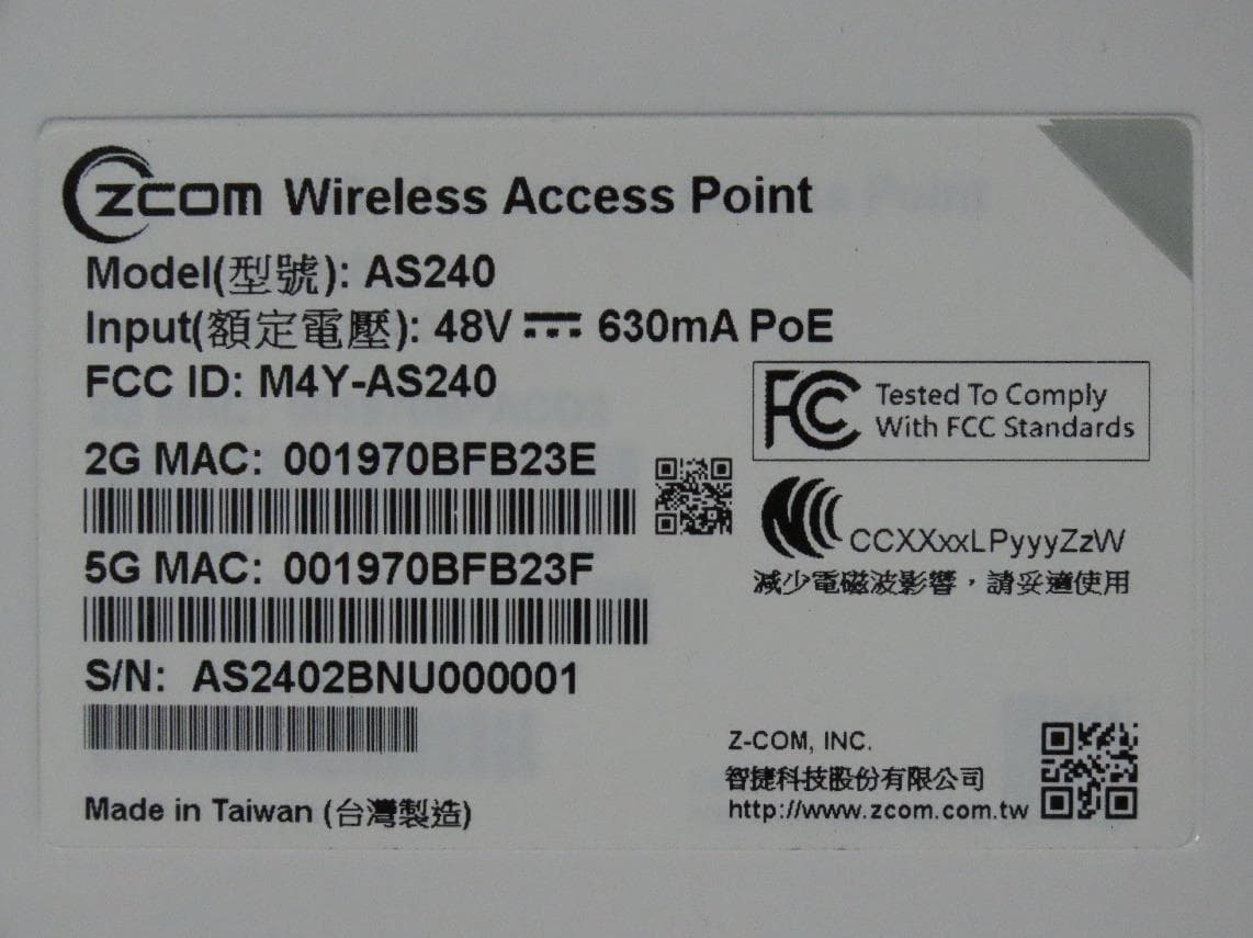
M4Y-AS240
Dec 13, 2022802.11ax Access Point
Equipment Class
DTS - Digital Transmission System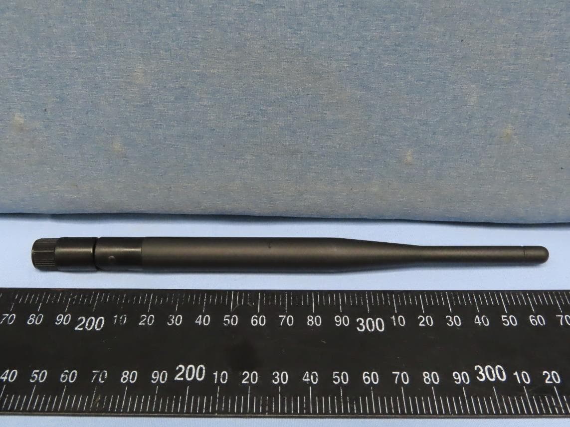
M4Y-AC720M
Aug 14, 2022802.11ac Wireless LAN USB Module
Equipment Class
NII - Unlicensed National Information Infrastructure TX
M4Y-SP230
Feb 21, 2021802.11 ac Wave 2 Access Point
Equipment Class
NII - Unlicensed National Information Infrastructure TX
M4Y-SP220C02
Jan 21, 2020802.11ac Access Point
Equipment Class
NII - Unlicensed National Information Infrastructure TX
M4Y-SP220C03
Jan 20, 20205GHz 11ac Wireless Bridge
Equipment Class
NII - Unlicensed National Information Infrastructure TX