M4Y-000580802.11b Wireless LAN Station Adapter/ Access Point
Z Com Inc
Click to zoom
Application Details
- Equipment Class
- DTS - Digital Transmission System
- Date of Grant
- Jul 17, 2003
- Application Purpose
- Original Equipment
- Date of Application
- Jul 17, 2003
- Equipment Note
- 802.11b Wireless LAN Station Adapter/ Access Point
- Frequency Range
- 2412.00000000 - 2462.00000000
- Company
- Z Com Inc
- Country
- Taiwan
Documents & Files
Document Text
Text extracted from the exhibit documents filed with the FCC. Open a document above to read the original.
Users Manual
1 11Mbps Wireless LAN Smart Station Adapter Quick Start Guide Version 1.6 The next-generation wireless LAN device – 11Mbps Wireless LAN Smart Station adapter, brings Ethernet-like performance to the wireless realm. Fully compliant with IEEE802.11b standard, the 11Mbps Wireless LAN Smart Station adapter also provides powerful features such as the Windows-based configuration utility, and WEP security. Maximize network efficiency while minimizing your network investment and maintenance costs. Package Content 11Mbps Wireless LAN Smart Station Adapter x 1 AC Power Adapter x 1 Software and Documentation CD x 1 Quick Installation Guide x 1 Note: If any of the above items are missing or damaged, contact your local dealer for support. Mechanical Description Top panel of the Wireless LAN Smart Access Point: The following table provides an overview of each LED activity: LED Definition Activity Description PWR Green Power enabled Off: No Wireless LAN traffic activity WLAN Green On: Associated to the Wireless AP and Wireless LAN traffic activity. Off: No Ethernet traffic activity Flashing: Wired LAN traffic activity LAN Green On: Connect to the Ethernet. Back panel of the Wireless LAN Smart Station Adapter: Power Socket ONLY use the power adapter supplied with the Wireless LAN Smart Station Adapter. Otherwise, the product may be damaged. LAN Ports Connect the Wireless LAN Smart Station Adapter to a hub or a PC with its UTP Ethernet 2 cable. Please note that, use the cross-over cable when you directly connect the Wireless LAN Smart Station Adapter to a PC. Default The button labeled “DEFAULT” enables you to restore the Wireless LAN Smart Station Adapter’s default setting. This is used when you forget the password. Installing the Wireless LAN Smart Station Adapter Connect the Wireless LAN Smart Station Adapter to a hub or a PC with its UTP Ethernet cable. Please note that, use the cross-over cable when you directly connect the Wireless LAN Smart Station Adapter to a PC. Connect the power adapter to the power socket on the Wireless LAN Smart Station Adapter, and plug the other end of the power pack into an electrical outlet. Note 1: ONLY use the power adapter supplied with the Wireless LAN Smart Station Adapter. Otherwise, the product may be damaged. Note 2: The button labeled “Default” enables you to restore the Wireless LAN Smart Station Adapter’s default setting. This is used when you forget the password. Please detach the DC power plug and press the “Default” button on the side panel of the Wireless LAN Smart Station Adapter. Reconnect the power and keep holding the button for 3 seconds then release it and press and keep holding it again for 10 seconds until the WLAN and LAN LED indicators become blinking rapidly. This will restore the Wireless LAN Smart Station Adapter’s default settings and enable you to configure the Smart Station via utility or Web again. Configuring the Wireless LAN Smart Station The 11Mbps Wireless LAN Smart Station Adapter allows configuration either via the configuration utility, known as Wireless Station Adapter Utility, and Web Management . Wireless Station Adapter Utility The following gives instructions guiding you through the installations of the Wireless Station Adapter Utility. 1. Insert the Product CD into the CD-ROM drive on your computer. 2. It will has the AutoRun function and show menu “Wireless 802.11b Smart Series” on the Windows desktop, choose the ”Smart Station ” and select the “Utility Setup”. 3. Follow the on-screen instructions to install the Wireless Station Adapter Utility. 3 4. Upon completion, execute the Smart Station Utility, and it will browse all the 11Mbps Wireless LAN Smart Station Adapter available on the network. 5. Select the Smart Station you want to configure. Enter the default password and click the LOGIN button. You will be able to view/make configuration of the Wireless LAN Smart Station Adapter as you desire. Note: The default password to get access to the Wireless LAN Smart Station Adapter is “default”. The Wireless Station Adapter Utility provides 5 items for you to monitor and configure the Wireless LAN Station: INFO, SECURITY, STATUS, AP BROWSER and ABOUT. INFO: This item shows the current information on the 11Mbps Wireless LAN Smart Station Adapter such as ESSID, Adapter’s name, Rate, IP Address, subnetmask, and default gateway. 4 You may click the SETUP button to configure those parameters. 5 Assigning the ESSID The ESSID is a unique ID used by Access Points and Stations to identify a wireless LAN. Wireless clients associating to any Access Point must have the same ESSID. The default ESSID is ANY. The ESSID can have up to 32 characters. Assigning the Adapter’s Name Assign specificity a unique name for Wireless LAN Smart Station Adapter. Assigning the Rate Wireless LAN Smart Station Adapter provides various data rate options for you to select. Data rates options include 1 Mbps, 2 Mbps, 5.5 Mbps, 11 Mbps, and Auto. In most networking scenarios, you will see that the factory-set default “Auto” will prove the most efficient. Assigning the IP Address Assign an IP address to your Smart Station if you wish to configure the Wireless Smart Station via the Web Management. Consult your network administrator to obtain an available IP address (the default IP address is 192.168.1.1). For further setup please refer to the following section. Assigning the subnet mask Assign an subnet mask to your Smart Station if you wish to configure the Wireless Smart Station via the Web Management. Consult your network administrator to obtain an available subnet mask. For further setup please refer to the following section. Assigning the default gateway Assign an default gateway to your Smart Station if you wish to configure the Wireless Smart Station via the Web Management. Consult your network administrator to obtain an available default gateway. Password It is highly recommended that you assign a new password to your Smart Station for safe…
Text truncated - open the document above for the full version.
Users Manual
Nov/5th/2002 1 11Mbps Wireless LAN Smart Access Point Quick Start Guide Version 3.0 The next-generation wireless LAN device – 11Mbps Wireless LAN Smart Access Point, brings Ethernet-like performance to the wireless realm. Fully compliant with IEEE802.11b standard, the 11Mbps Wireless LAN Smart Access Point also provides powerful features such as the Windows-based configuration utility, WEP security, SNMP and more. Maximize network efficiency while minimizing your network investment and maintenance costs. Package Content 11Mbps Wireless LAN Smart Access Point x 1 AC Power Adapter x 1 Software and Documentation CD x 1 Quick Installation Guide x 1 Note: If any of the above items are missing or damaged, contact your local dealer for support. Installing the Wireless LAN Smart Access Point Connect the Wireless LAN Smart Access Point to a hub or a PC with its UTP Ethernet cable. Please note that, use the cross-over cable when you directly connect the Wireless LAN Smart Access Point to a PC. Connect the power adapter to the power socket on the Wireless LAN Smart Access Point, and plug the other end of the power pack into an electrical outlet. Warning 1: ONLY use the power adapter supplied with the Wireless LAN Smart Access Point. Otherwise, the product may be damaged. Note 2: The button labeled “Default” enables you to restore the Wireless LAN Smart Access Point’s default setting. This is used when you forget the password. Please detach the DC power plug and press the “DEFAULT” button on the side panel of the Wireless LAN Smart Access Point. Reconnect the power and keep holding the button for 3 seconds then release it and press and keep holding it again for 10 seconds until the WLAN and LAN LED indicators become blinking rapidly. This will restore the Wireless LAN Smart Access Nov/5th/2002 2 Point’s default settings and enable you to configure the Access Point via utility or Web again. Configuring the Wireless LAN Smart Access Point The 11Mbps Wireless LAN Smart Access Point allows configuration either via the configuration utility, known as Access Point Utility, and Web Management . Wireless Access Point Utility The following gives instructions guiding you through the installations of the Wireless Access Point Utility. 1. Insert the Product CD into the CD-ROM drive on your computer. 2. It will has the AutoRun function and show menu “Wireless 802.11b Smart Series” on the Windows desktop, choose the ”Access Point” and select the “Utility Setup”. 3. Follow the on-screen instructions to install the Wireless Access Point Utility. 4. Upon completion, execute the Wireless Access Point Utility, and it will browse all the 11Mbps Wireless LAN Smart Access Point available on the network. 5. Select the Access Point you want to configure. Enter the default password and click the LOGIN button. You will be able to view/make configuration of the Wireless LAN Smart Access Point as you desire. Note: The default password to get access to the Wireless LAN Smart Access Point is “default”. Nov/5th/2002 3 The Wireless Access Point Utility provides 3 items for you to monitor and configure the Wireless LAN Access Point: INFO, SECURITY and ABOUT. INFO: This item shows the current information on the 11Mbps Wireless LAN Smart Access Point such as BSSID, AP’s Name, SSID, Channel, Mode, SNMP, DHCP Client, IP Address, subnetmask, default gateway, and LabelNosee. Nov/5th/2002 4 Nov/5th/2002 5 You may click the SETUP button to configure those parameters. Assigning the SSID The SSID is a unique ID given to the Wireless LAN Smart Access Point. Assign an SSID to your Wireless Smart Access Point. The SSID can have up to 32 characters. Assigning the Channel Select a clear channel as an operational channel for your Wireless LAN Smart Access Point. Assigning the AP’s Name Assign specificity a unique name for the Wireless LAN Smart Access Point. Assigning the Mode Wireless LAN Smart Access Point can be configured in a variety of network system configurations such as AP only, Repeater only, and AP with Repeater. AP Only – Enables the Access Point to act as a wireless bridge connecting to your network backbone and communicating between Ethernet LAN and Wireless station. Nov/5th/2002 6 Repeater Only – The repeater mode extends the radio coverage. The repeater can be at the center of the two (or more) Access Points that also need to set with repeater mode in the situation in which the distance is too far apart or are separated by some form of obstructive interference. If Repeater is selected, the repeater and Access Point must set with the same channel to transfer data. AP with Repeater - Allows that Access point to act as Access Point and Repeater operation simultaneously. For repeater, the same channel is required to Access Point. SNMP SNMP is Simple Network Management Protocol that has became the standard to Nov/5th/2002 7 manage network management and monitor of network devices and their functions. If SNMP is enabled, devices can use SNMP tool to manage and monitor the Wireless LAN Smart Access Point from remote control. DHCP Client Assign an IP address to the Wireless station. You may either set the wireless station to obtain an IP address from DHCP server, or to be assigned with a fixed IP address. If DHCP is enabled, the IP Address field displays the IP Address that is dynamically assigned to the AP by the network DHCP server and the IP Mask field displays the IP Mask utilized by the network DHCP server. The default setting is: Disable Assigning the IP Address Assign an IP address to your Access Point if you wish to configure the Wireless Access Point via the Web Management. Consult your network administrator to obtain an available IP address (the default IP address is 192.168.1.1). For further setup please refer to the following section. Assigning the subnetmask Assign a subnet mask to your Access Point if you wish to configure the Wireless Access Point via the Web Management. Consult your network administrator…
Text truncated - open the document above for the full version.
External Photos
Company : Z-COM, INC. Page : 1 of 9 Product : 802.11b Wireless LAN Station Adapter Model : XI-580 Company : Z-COM, INC. Page : 2 of 9 Product : 802.11b Wireless LAN Station Adapter Model : XI-580 Company : Z-COM, INC. Page : 3 of 9 Product : 802.11b Wireless LAN Station Adapter Model : XI-580 Company : Z-COM, INC. Page : 4 of 9 Product : 802.11b Wireless LAN Station Adapter Model : XI-580 Company : Z-COM, INC. Page : 5 of 9 Product : 802.11b Wireless LAN Station Adapter Model : XI-580 Company : Z-COM, INC. Page : 6 of 9 Product : 802.11b Wireless LAN Station Adapter (For Adapter) Model : M1-10S05 Company : Z-COM, INC. Page : 7 of 9 Product : 802.11b Wireless LAN Station Adapter (For Adapter) Model : M1-10S05 Company : Z-COM, INC. Page : 8 of 9 Product : 802.11b Wireless LAN Station Adapter (For Adapter) Model : M1-10S05 Company : Z-COM, INC. Page : 9 of 9 Product : 802.11b Wireless LAN Station Adapter (For Adapter) Model : M1-10S05
ID Label/Location Info
Company : Z-COM, INC. Model: XI-580 Product : 802.11b Wireless LAN Station Adapter 802.11b Wireless LAN Station Adapter Model No: XI-580 FCC IDM4Y-000580 This device complies with part 15 of the FCC Rules. Operation is subject to the following two conditions: [1] this device may not cause harmful interference and [2] this device must accept any interference received, including interference that may cause undesired operation. S/N Made in Taiwan
ID Label/Location Info
Company : Z-COM, INC. Model: XI-1280 Product : 802.11b Wireless LAN Access Point 802.11b Wireless LAN Access Point Model No: XI-1280 FCC IDM4Y-000580 This device complies with part 15 of the FCC Rules. Operation is subject to the following two conditions: [1] this device may not cause harmful interference and [2] this device must accept any interference received, including interference that may cause undesired operation. S/N Made in Taiwan
Internal Photos
Company : Z-COM, INC. Page : 1 of 3 Product : 802.11b Wireless LAN Station Adapter Model : XI-580 Company : Z-COM, INC. Page : 2 of 3 Product : 802.11b Wireless LAN Station Adapter Model : XI-580 Company : Z-COM, INC. Page : 3 of 3 Product : 802.11b Wireless LAN Station Adapter Model : XI-580
Operational Description
Description of Operation EUT is a 802.11b Wireless LAN Access Point with 11 channels. This device provided four kind of transmitting speed 1,2,5.5 and 11Mbps. The device of RF carrier is DQPSK,DB PSK and CCK.The device adapts direct sequence spread spectrum modulation. The Connector antenna was scolded on PCB provided diversity function to improve the receiving function.This 802.11b Wireless LAN Access Point is an IEEE 802.11b Wireless LAN adapter. It allows your computer to connect to a wireless network and to share resources, such as files or printers without being bound to the network wires. Operation in 2.4GHz Direct Sequence Spread Spectrum (D.S.S.S) radio transmission, the 802.11b Wireless LAN Access Point transfers data at speeds up to 64/128-bit Wired Equivalent Protection(WEP) algorithm is used. In addition, its standard compliance ensures that it can communicate with any 802.11b network.
Operational Description
Description of Operation EUT is a 802.11b Wireless LAN Station Adapter with 11 channels. This device provided four kind of transmitting speed 1,2,5.5 and 11Mbps. The device of RF carrier is DQPSK,DB PSK and CCK.The device adapts direct sequence spread spectrum modulation. The Connector antenna was scolded on PCB provided diversity function to improve the receiving function.This 802.11b Wireless LAN Station Adapter is an IEEE 802.11b Wireless LAN adapter. It allows your computer to connect to a wireless network and to share resources, such as files or printers without being bound to the network wires. Operation in 2.4GHz Direct Sequence Spread Spectrum (D.S.S.S) radio transmission, the 802.11b Wireless LAN Station Adapter transfers data at speeds up to 64/128-bit Wired Equivalent Protection(WEP) algorithm is used. In addition, its standard compliance ensures that it can communicate with any 802.11b network.
Operational Description
The function in the RF-chip XI-580 and XI-1280 are the same , the only one difference----SOFTWARE is different for each. (a)XI-580.....The software is: Station Adapter for client. (b)XI-1280....The software is:Access Point.
RF Exposure Info
Ecom Sertech Corp. Rm. 258, Bldg. 17, NO.195, Sec. 4 Chung Hsing Rd.,Chu -Tung Chen, Hsinchu, Taiwan 310, R.O.C TEL:886 - 3 - 5918012 FAX : 886 - 3 - 5825720 FCC ID :M4Y-000580 Report No.:ER03-05-040FRF Page 1 of 2 RF EXPOSURE EVALUATION According to FCC 1.1310 : The criteria listed in the following table shall be used to evaluate the environment impact of human exposure to radio frequency (RF) radiation as specified in 1.1307(b) LIMITS FOR MAXIMUM PERMISSIBLE EXPOSURE (MPE) Frequency Range (MHz) Electric Field Strength (V/m) Magnetic Field Strength (A/m) Power Density (mW/cm 2 ) Average Time (A) Limits for Occupational / Control Exposures 300-1,500 -- -- F/300 6 1,500-100,000 -- -- 5 6 (B) Limits for General Population / Uncontrol Exposures 300-1,500 -- -- F/1500 6 1,500-100,000 -- -- 1 30 FRIIS FORMULA Friis transmission formula : Pd = (Pout*G)/(4*pi*r 2 ) Where Pd = power density in mW/cm 2 Pout = output power to antenna in mW G = gain of antenna in linear scale Pi = 3.1416 R = distance between observation point and center of the radiator in cm Pd id the limit of MPE, 1 mW/cm2. If we know the maximum gain of the antenna and the total power input to the antenna, through the calculation, we will know the distance r where the MPE limit is reached. EUT OPERATING CONDITION A software provided by client enabled the EUT to transmit and receive data at lowest, middle and highest channel individually. Ecom Sertech Corp. Rm. 258, Bldg. 17, NO.195, Sec. 4 Chung Hsing Rd.,Chu -Tung Chen, Hsinchu, Taiwan 310, R.O.C TEL:886 - 3 - 5918012 FAX : 886 - 3 - 5825720 FCC ID :M4Y-000580 Report No.:ER03-05-040FRF Page 2 of 2 TEST RESULT OF RF EXPOSURE EVALUATION Test Item : RF Exposure Evaluation Data Test Mode : Normal Operation ANTENNA GAIN Antenna Gain:The maximum Gain measured in fully anechoic chamber is 2dBi linear scale. OUTPUT POWER INTO ANTENNA & RF EXPOSURE EVALUATION DISTANCE Channel Channel Frequency (MHz) Output Power to Antenna (dBm) Power density in mW/cm2 at Friis formula when r=20cm(mW/cm2) LIMITS CH1 2412.00 13.13 0.006482 1 CH6 2437.00 13.54 0.007124 1 CH11 2462.00 12.55 0.005672 1 The power density Pd (4 th column) at a distance of 20cm calculated from the Friis transmission formula is far belowthe limit of 1 mW/cm 2 . So, RF exposure limit warning or SAR test are not required.
Test Report
Ecom Sertech Corp. Rm. 258, Bldg. 17, NO.195, Sec. 4 Chung Hsing Rd.,Chu -Tung Chen, Hsinchu, Taiwan 310, R.O.C TEL:886 - 3 - 5918012 FAX : 886 - 3 - 5825720 FCC ID :M4Y-000580 Report No.:ER03-05-040FRF Page 1 of 40 TEST REPORT Product Name : 802.11b Wireless LAN Station Adapter Model Number : XI-580 Applicant : Z-COM, INC. Address : 7F-2, NO.9,PROSPERITY 1 ROAD., SCIENCE-BASED INDUSTRIAL PARK, HSINCHU, TAIWAN, R.O.C. Date Received : MAY. 14, 2003 Date Tested : MAY. 14~JUN. 03, 2003 Notes : 1. This report will be invalid if duplicated or photocopied in part. 2. This report refers only to the specimen(s) submitted to testing, and be invalid as seperately used. 3. This report is invalid without examination stamp and signature of this institute. 4. The tested specimen(s) will be preserved for thirty days from the data issued. 5. The report must not be used to claim product certification, approval, or endorsement by NVLAP, NIST, or any agency of the federal government. Ecom Sertech Corp. Rm. 258, Bldg. 17, NO.195, Sec. 4 Chung Hsing Rd.,Chu -Tung Chen, Hsinchu, Taiwan 310, R.O.C TEL:886 - 3 - 5918012 FAX : 886 - 3 - 5825720 FCC ID :M4Y-000580 Report No.:ER03-05-040FRF Page 2 of 40 Test Report Cerification Product Name : 802.11b Wireless LAN Station Adapter Model Number : XI-580 Applicant : Z-COM, INC. Measurement Standard : 47 CFR Part 15, Subpart B and Subpart C (Section 15.247), ANSI C63.4-2001 Ecom Sertech Corp. Rm. 258, Bldg. 17, NO.195, Sec. 4 Chung Hsing Rd.,Chu -Tung Chen, Hsinchu, Taiwan 310, R.O.C TEL:886 - 3 - 5918012 FAX : 886 - 3 - 5825720 FCC ID :M4Y-000580 Report No.:ER03-05-040FRF Page 3 of 40 TABLE OF CONTENTS TITLE PAGE NO. 1. GENERAL INFORMATION .................................................................................................................... 5 1.1GENERAL STATEMENT.................................................................................................................. 5 1.2 GENERAL DESCRIPTION OF EUT & POWER............................................................................. 5 1.3 DESCRIPTION OF PERIPHERALS.................................................................................................6 1.4 EUT & PERIPHERALS SETUP DIAGRAM.................................................................................... 6 1.5 EUT OPERATING CONDITION ..................................................................................................... 7 1.6 DESCRIPTION OF TEST SITE ........................................................................................................ 8 1.7 SUMMARY OF TEST RESULTS ....................................................................................................8 2. CONDUCTED POWERLINE TEST ........................................................................................................ 9 2.1 TEST EQUIPMENTS ........................................................................................................................ 9 2.2 TEST SETUP ..................................................................................................................................... 9 2.3 CONDUCTED POWER LINE EMISSION LIMIT .......................................................................... 10 2.4 TEST PROCEDURE.......................................................................................................................... 10 2.5 UNCERTAINTY OF CONDUCTED EMISSION .............................................................................. 10 2.6 CONDUCTED RF VOLTAGE MEASUREMENT ............................................................................ 11 2.7 PHOTOS OF CONDUCTION TEST ..................................................................................................12 3. RADIATED EMISSION TEST................................................................................................................. 13 3.1 TEST EQUIPMENTS .......................................................................................................................... 13 3.2 TEST SETUP ....................................................................................................................................... 13 3.3 RADIATION LIMIT............................................................................................................................ 14 3.4 TEST PROCEDURES ......................................................................................................................... 15 3.5 UNCERTAINTY OF RADIATED EMISSION .................................................................................. 15 3.6 RADIATED RF NOISE MEASUREMENT ....................................................................................... 16-23 3.7 PHOTOS OF OPEN SITE ................................................................................................................... 24-26 4. 6dB BANDWIDTH MEASUREMENT .................................................................................................... 27 4.1 TEST EQUIPMENTS .......................................................................................................................... 27 4.2 TEST SETUP ....................................................................................................................................... 27 4.3 LIMITS OF 6dB BANDWIDTH MEASUREMENT .......................................................................... 27 4.4 TEST PROCEDURE............................................................................................................................ 27 4.5 UNCERTAINTY OF CONDUCTED EMISSION .............................................................................. 27 4.6 TEST RESULTS .................................................................................................................................. 28 4.7 PHOTO OF 6DB BANDWIDTH MEASURERMENT ...................................................................... 29 5. MAXIMUM PEAK O…
Text truncated - open the document above for the full version.
Test Report
Ecom Sertech Corp. Rm. 258, Bldg. 17, NO.195, Sec. 4 Chung Hsing Rd.,Chu -Tung Chen, Hsinchu, Taiwan 310, R.O.C TEL:886 - 3 - 5918012 FAX : 886 - 3 - 5825720 FCC ID M4Y-000580 Report No.ER03-06-065FRF Page 1 of 40 TEST REPORT Product Name 802.11b Wireless LAN Access Point Model Number XI-1280 Applicant Z-COM, INC. Address 7F-2, NO.9,PROSPERITY 1 ROAD., SCIENCE-BASED INDUSTRIAL PARK, HSINCHU, TAIWAN, R.O.C. Date Received MAY. 14, 2003 Date Tested MAY. 14~JUN. 03, 2003 Notes 1. This report will be invalid if duplicated or photocopied in part. 2. This report refers only to the specimen(s) submitted to testing, and be invalid as seperately used. 3. This report is invalid without examination stamp and signature of this institute. 4. The tested specimen(s) will be preserved for thirty days from the data issued. 5. The report must not be used to claim product certification, approval, or endorsement by NVLAP, NIST, or any agency of the federal government. Ecom Sertech Corp. Rm. 258, Bldg. 17, NO.195, Sec. 4 Chung Hsing Rd.,Chu -Tung Chen, Hsinchu, Taiwan 310, R.O.C TEL:886 - 3 - 5918012 FAX : 886 - 3 - 5825720 FCC ID M4Y-000580 Report No.ER03-06-065FRF Page 2 of 40 Test Report Cerification Product Name : 802.11b Wireless LAN Access Point Model Number : XI-1280 Applicant : Z-COM, INC. Measurement Standard : 47 CFR Part 15, Subpart B and Subpart C (Section 15.247), ANSI C63.4-2001 WE HEREBY CERTIFY THAT: The measurements shown in the attachment were made in accordance with the procedures indicated, and the energy emitted by the equipment was found to be within the limits applicable. We assume full responsibility for the accuracy and completeness of these measurements and vouch for the qualifications of all persons taking them. Ecom Sertech Corp. Rm. 258, Bldg. 17, NO.195, Sec. 4 Chung Hsing Rd.,Chu -Tung Chen, Hsinchu, Taiwan 310, R.O.C TEL:886 - 3 - 5918012 FAX : 886 - 3 - 5825720 FCC ID M4Y-000580 Report No.ER03-06-065FRF Page 3 of 40 TABLE OF CONTENTS TITLE PAGE NO. 1. GENERAL INFORMATION .................................................................................................................... 5 1.1GENERAL STATEMENT.................................................................................................................. 5 1.2 GENERAL DESCRIPTION OF EUT & POWER............................................................................. 5 1.3 DESCRIPTION OF PERIPHERALS.................................................................................................6 1.4 EUT & PERIPHERALS SETUP DIAGRAM.................................................................................... 6 1.5 EUT OPERATING CONDITION ..................................................................................................... 7 1.6 DESCRIPTION OF TEST SITE ........................................................................................................ 8 1.7 SUMMARY OF TEST RESULTS ....................................................................................................8 2. CONDUCTED POWERLINE TEST ........................................................................................................ 9 2.1 TEST EQUIPMENTS ........................................................................................................................ 9 2.2 TEST SETUP ..................................................................................................................................... 9 2.3 CONDUCTED POWER LINE EMISSION LIMIT .......................................................................... 10 2.4 TEST PROCEDURE.......................................................................................................................... 10 2.5 UNCERTAINTY OF CONDUCTED EMISSION .............................................................................. 10 2.6 CONDUCTED RF VOLTAGE MEASUREMENT ............................................................................ 11 2.7 PHOTOS OF CONDUCTION TEST ..................................................................................................12 3. RADIATED EMISSION TEST................................................................................................................. 13 3.1 TEST EQUIPMENTS .......................................................................................................................... 13 3.2 TEST SETUP ....................................................................................................................................... 13 3.3 RADIATION LIMIT............................................................................................................................ 14 3.4 TEST PROCEDURES ......................................................................................................................... 15 3.5 UNCERTAINTY OF RADIATED EMISSION .................................................................................. 15 3.6 RADIATED RF NOISE MEASUREMENT ....................................................................................... 16-23 3.7 PHOTOS OF OPEN SITE ................................................................................................................... 24-26 4. 6dB BANDWIDTH MEASUREMENT .................................................................................................... 27 4.1 TEST EQUIPMENTS ......................................................................................................................…
Text truncated - open the document above for the full version.
Contact Information
Applicant
Jeff jiang(R&D DIV Director)
Test Firm
Compliance Certification Services Inc.Paul Liau
Technical Specifications
| # | Rule Parts | Frequency Range | Power Output |
|---|---|---|---|
| 1 | 15C | 2.41 GHz - 2.46 GHz | 22.00 mW |
Other Applications from Z Com Inc
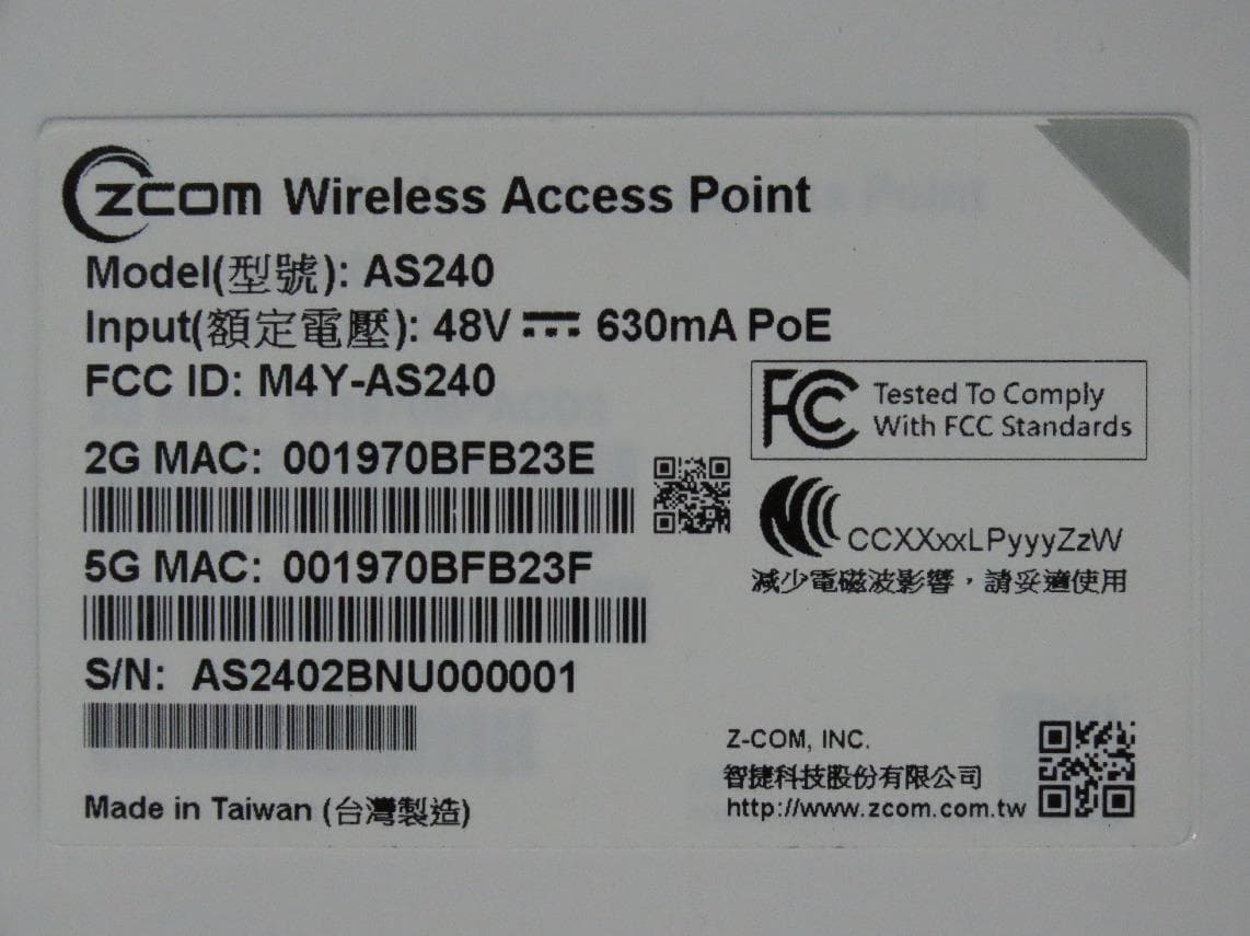
M4Y-AS240
Dec 13, 2022802.11ax Access Point
Equipment Class
DTS - Digital Transmission System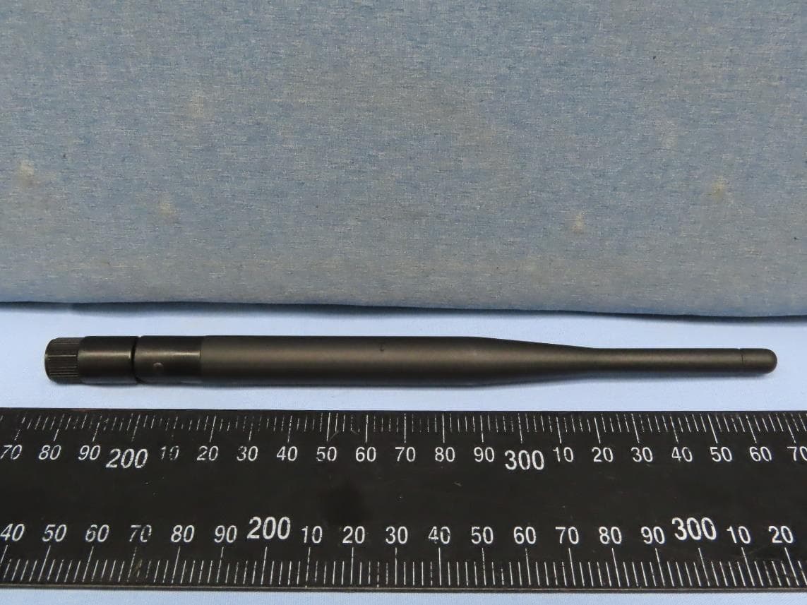
M4Y-AC720M
Aug 14, 2022802.11ac Wireless LAN USB Module
Equipment Class
NII - Unlicensed National Information Infrastructure TX
M4Y-SP230
Feb 21, 2021802.11 ac Wave 2 Access Point
Equipment Class
NII - Unlicensed National Information Infrastructure TX
M4Y-SP220C02
Jan 21, 2020802.11ac Access Point
Equipment Class
NII - Unlicensed National Information Infrastructure TX
M4Y-SP220C03
Jan 20, 20205GHz 11ac Wireless Bridge
Equipment Class
NII - Unlicensed National Information Infrastructure TX