M4Y-002250802.11b Wireless Router
Z Com Inc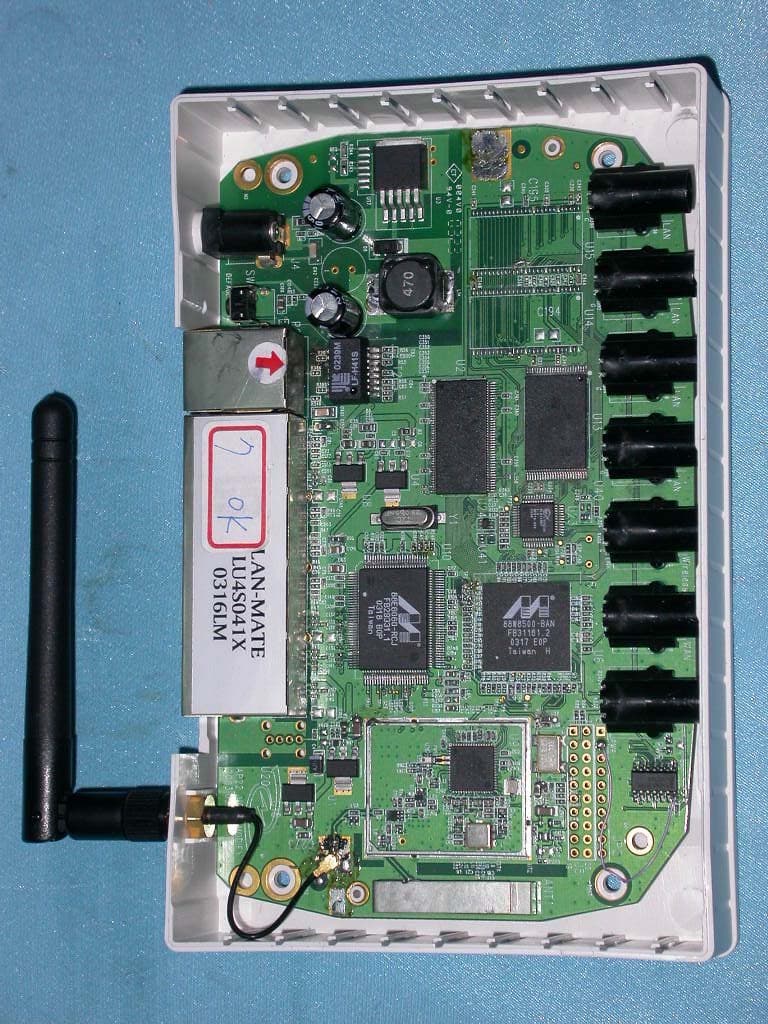
Click to zoom
Application Details
- Equipment Class
- DTS - Digital Transmission System
- Date of Grant
- Jul 16, 2003
- Application Purpose
- Original Equipment
- Date of Application
- Jul 16, 2003
- Equipment Note
- 802.11b Wireless Router
- Frequency Range
- 2412.00000000 - 2462.00000000
- Company
- Z Com Inc
- Country
- Taiwan
Documents & Files
Document Text
Text extracted from the exhibit documents filed with the FCC. Open a document above to read the original.
Users Manual
1 Chapter 1: Introduction This manual contains detail instructions, on how to setup and operate the VPN Internet Gateway. The VPN Internet Gateway provides an easy and cost effective way to communicate securely over a public network, such as the Internet. You can configure the VPN Internet Gateway to automatically encrypt all data transmitted to a particular site or sites over the Internet. The VPN Internet Gateway can create a secure connection between two or more sites. The VPN Internet Gateway is equipped with: • A WAN Ethernet port (connects to any Cable/XDSL modem) • 4 LAN Ethernet ports (connect to a PC client or a Hub/switch etc.) • One asynchronous port (connects to a dial up modem or a ISDN TA) Connect any Cable/XDSL modem to the VPN Internet Gateway, to establish a high speed Internet connection. Once an Internet connection is made, you can start establishing VPN connections. Those who require a private and secure connection will find this device an easy and cost effective solution to a lease line connection. The asynchronous port can be connected to a dial-up modem or to an ISDN TA and provides you with a backup Internet connection should the Cable/xDSL connection fail. If there is no Cable/xDSL service in your area, the asynchronous port can also serve as your Internet access connection. The VPN Internet Gateway provides a total solution for those SOHO (Small Office and Home Office), SMB (Small and Medium size Businesses) and ROBO (Remote Office and Branch Office) users, who require a VPN and other sophisticated functions at a cost effective price. 2 Features z Supports Virtual Private Network (VPN) connections (IPSec) z Supports up to 8 IPSec tunnel connections z Supports VPN client software (Safenet and SSH) z Supports DES/3DES Encryption, IP Encapsulating Security Payload (ESP), Authentication (MD5/SHA-1) z Shared Internet connection via any Cable or xDSL modem z Asynchronous port for backup or dial-up Internet connection z Supports up to 253 users z Provides solid firewall protection for LAN clients/computers z Built-in high speed 4 port 10/100 switch to connect to computers or to additional switches/hubs z Provides centralization of all network address settings (DHCP) z Comprehensive device monitoring system: Device status, Device information, System Tools, Intruder Detection log and more... z Easy-to-use, Web-based setup and configuration z Dynamic DNS to have Web and other Servers behind a Dynamic IP address z Acts as a Virtual server to enable remote access to Web, FTP, and other services on your network z DMZ for full 2-way communication between your LAN and the Internet z URL filtering function z Supports the UPnP protocol z E-Mail alert when a network security breach occurs Package Contents Please inspect your package. The following items should be included: 1). One VPN Internet Gateway (the Device) 2). One Power adapter 3). One User’s Guide If any of the above items are damaged or missing, please contact your dealer immediately. 3 Minimum System Requirements z Microsoft Internet Explorer 4.0 (or later version) or Netscape Navigator 4.0 (or later version) z One computer with an installed 10Mbps, 100Mbps or 10/100Mbps Ethernet card z One external xDSL or Cable modem with an Ethernet port (RJ-45) z One Modem or ISDN TA (if a dialup connection is needed) z One RJ-45 Cable/XDSL Internet connection z TCP/IP protocol installed in your computer z UTP network Cable with a RJ-45 connector Pre-Installation Checklist Before installing the Internet Gateway, you should: z Have carefully read the entire manual. z Be familiar with the terminology and concepts of browsers. (This guide works under the assumption that you are proficient with the browsers you are using). z Have met all the hardware and software requirements. 4 The Gateway’s Rear View The diagram below shows the Internet Gateway’s rear panel and is where all the hardware connections are made. Rear View Ports Description Power (12VDC) The power port is where you connect the DC power adapter WAN The WAN 10M Ethernet port is where you connect your ADSL/Cable modem. Serial The Serial port is where you connect the 56K modem / ISDN TA Reset If you want the device to have the factory default settings, press the reset button and hold it for 5 ~ 6 seconds. This will load the factory default settings into the device. Please be careful. Do not press the reset button unless you want to clear the current configurations. Ports 1-4 There are four LAN ports on the rear panel (supports auto crossover). This is where you connect network devices, such as PCs, switches, hubs, print servers, LAN servers or other network devices. 12VDC 5 The Gateway’s Front Panel LED On the router’s front panel there are LED lights that inform you of the router’s current status. Below is an explanation of each LED and its function. LED LED Status Description LAN (1-4) Link/Act Off Green LED will NOT Light if there is no connection ON Green LED will LIGHT when a connection has been established. Blink Green LED will BLINK if packets are been transmitted or received Serial Off Green LED will NOT Light if there is no connection ON Green LED will LIGHT when a link has been established. WAN Off Green LED will NOT Light when a link has not been established. ON Green LED will LIGHT when a link has been established. 6 LED LED Status Description STATUS Blink Yellow LED will BLINK when the device is booting up or upgrading a firmware. POWER Off NO Power ON Red LED will LIGHT if the Gateway is receiving power. Hardware Installation Setup The diagram below shows how the Internet Gateway is typically setup. 7 When you setup the hardware installation please note the following. 1. Make sure that the power supply outlet voltage is compatible with the power adapters of your PCs, Cable/XDSL modem and the Internet Gateway. 2. For the Internet Gateway, only use the power adapter that comes with it. 3. Connect a network cable from your PC’s Ethernet port to one of the LAN ports…
Text truncated - open the document above for the full version.
ID Label/Location Info
Company : Z-COM, INC. Model: XI-2250 Product : 802.11b Wireless Router 802.11b Wireless Router Model No: XI-2250 FCC IDM4Y-002250 This device complies with part 15 of the FCC Rules. Operation is subject to the following two conditions: [1] this device may not cause harmful interference and [2] this device must accept any interference received, including interference that may cause undesired operation. S/N Made in Taiwan
Internal Photos
Company : Z-COM, INC. Page : 1 of 6 Product : 802.11b Wireless Router Model : XI-2250 Company : Z-COM, INC. Page : 2 of 6 Product : 802.11b Wireless Router Model : XI-2250 Company : Z-COM, INC. Page : 3 of 6 Product : 802.11b Wireless Router Model : XI-2250 Company : Z-COM, INC. Page : 4 of 6 Product : 802.11b Wireless Router Model : XI-2250 Company : Z-COM, INC. Page : 5 of 6 Product : 802.11b Wireless Router Model : XI-2250 Company : Z-COM, INC. Page : 6 of 6 Product : 802.11b Wireless Router Model : XI-2250
Operational Description
Description of Operation EUT is a 802.11b Wireless Router with 11 channels. This device provided four kind of transmitting speed 1,2,5.5 and 11Mbps. The device of RF carrier is DQPSK,DB PSK and CCK.The device adapts direct sequence spread spectrum modulation. The Connector antenna was scolded on PCB provided diversity function to improve the receiving function.This 802.11b Wireless Router is an IEEE 802.11b Wireless LAN adapter. It allows your computer to connect to a wireless network and to share resources, such as files or printers without being bound to the network wires. Operation in 2.4GHz Direct Sequence Spread Spectrum (D.S.S.S) radio transmission, the 802.11b Wireless Router transfers data at speeds up to 64/128-bit Wired Equivalent Protection(WEP) algorithm is used. In addition, its standard compliance ensures that it can communicate with any 802.11b network.
RF Exposure Info
Ecom Sertech Corp. Rm. 258, Bldg. 17, NO.195, Sec. 4 Chung Hsing Rd.,Chu -Tung Chen, Hsinchu, Taiwan 310, R.O.C TEL:886 - 3 - 5918012 FAX : 886 - 3 - 5825720 FCC ID M4Y-002250 Report No. ER03-05-041FRF Page 1 of 2 RF EXPOSURE EVALUATION According to FCC 1.1310 : The criteria listed in the following table shall be used to evaluate the environment impact of human exposure to radio frequency (RF) radiation as specified in 1.1307(b) LIMITS FOR MAXIMUM PERMISSIBLE EXPOSURE (MPE) Frequency Range (MHz) Electric Field Strength (V/m) Magnetic Field Strength (A/m) Power Density (mW/cm 2 ) Average Time (A) Limits for Occupational / Control Exposures 300-1,500 -- -- F/300 6 1,500-100,000 -- -- 5 6 (B) Limits for General Population / Uncontrol Exposures 300-1,500 -- -- F/1500 6 1,500-100,000 -- -- 1 30 FRIIS FORMULA Friis transmission formula : Pd = (Pout*G)/(4*pi*r 2 ) Where Pd = power density in mW/cm 2 Pout = output power to antenna in mW G = gain of antenna in linear scale Pi = 3.1416 R = distance between observation point and center of the radiator in cm Pd id the limit of MPE, 1 mW/cm2. If we know the maximum gain of the antenna and the total power input to the antenna, through the calculation, we will know the distance r where the MPE limit is reached. EUT OPERATING CONDITION A software provided by client enabled the EUT to transmit and receive data at lowest, middle and highest channel individually. Ecom Sertech Corp. Rm. 258, Bldg. 17, NO.195, Sec. 4 Chung Hsing Rd.,Chu -Tung Chen, Hsinchu, Taiwan 310, R.O.C TEL:886 - 3 - 5918012 FAX : 886 - 3 - 5825720 FCC ID M4Y-002250 Report No. ER03-05-041FRF Page 2 of 2 TEST RESULT OF RF EXPOSURE EVALUATION Test Item RF Exposure Evaluation Data Test Mode Normal Operation ANTENNA GAIN Antenna GainThe maximum Gain measured in fully anechoic chamber is 2dBi linear scale. OUTPUT POWER INTO ANTENNA & RF EXPOSURE EVALUATION DISTANCE Channel Channel Frequency (MHz) Output Power to Antenna (dBm) Power density in mW/cm2 at Friis formula when r=20cm(mW/cm2) LIMITS CH1 2412.00 15.60 0.011448 1 CH6 2437.00 15.90 0.012267 1 CH11 2462.00 16.60 0.014412 1 The power density Pd (4 th column) at a distance of 20cm calculated from the Friis transmission formula is far belowthe limit of 1 mW/cm 2 . So, RF exposure limit warning or SAR test are not required.
Test Report
Ecom Sertech Corp. Rm. 258, Bldg. 17, NO.195, Sec. 4 Chung Hsing Rd.,Chu -Tung Chen, Hsinchu, Taiwan 310, R.O.C TEL:886 - 3 - 5918012 FAX : 886 - 3 - 5825720 FCC ID M4Y-002250 Report No. ER03-05-041FRF Page 1 of 40 TEST REPORT Product Name 802.11b Wireless Router Model Number XI-2250 Applicant Z-COM, INC. Address 7F-2, NO.9,PROSPERITY 1 ROAD., SCIENCE-BASED INDUSTRIAL PARK, HSINCHU, TAIWAN, R.O.C. Date Received MAY. 15, 2003 Date Tested MAY. 15~JUN. 10, 2003 Notes 1. This report will be invalid if duplicated or photocopied in part. 2. This report refers only to the specimen(s) submitted to testing, and be invalid as seperately used. 3. This report is invalid without examination stamp and signature of this institute. 4. The tested specimen(s) will be preserved for thirty days from the data issued. 5. The report must not be used to claim product certification, approval, or endorsement by NVLAP, NIST, or any agency of the federal government. Ecom Sertech Corp. Rm. 258, Bldg. 17, NO.195, Sec. 4 Chung Hsing Rd.,Chu -Tung Chen, Hsinchu, Taiwan 310, R.O.C TEL:886 - 3 - 5918012 FAX : 886 - 3 - 5825720 FCC ID M4Y-002250 Report No. ER03-05-041FRF Page 2 of 40 Test Report Cerification Product Name : 802.11b Wireless Router Model Number : XI-2250 Applicant : Z-COM, INC. Measurement Standard : 47 CFR Part 15, Subpart B and Subpart C (Section 15.247), ANSI C63.4-2001 WE HEREBY CERTIFY THAT: The measurements shown in the attachment were made in accordance with the procedures indicated, and the energy emitted by the equipment was found to be within the limits applicable. We assume full responsibility for the accuracy and completeness of these measurements and vouch for the qualifications of all persons taking them. Ecom Sertech Corp. Rm. 258, Bldg. 17, NO.195, Sec. 4 Chung Hsing Rd.,Chu -Tung Chen, Hsinchu, Taiwan 310, R.O.C TEL:886 - 3 - 5918012 FAX : 886 - 3 - 5825720 FCC ID M4Y-002250 Report No. ER03-05-041FRF Page 3 of 40 TABLE OF CONTENTS TITLE PAGE NO. 1. GENERAL INFORMATION............................................................................................................5 1.1GENERAL STATEMENT ...........................................................................................................5 1.2 GENERAL DESCRIPTION OF EUT & POWER ......................................................................5 1.3 DESCRIPTION OF PERIPHERALS ..........................................................................................6 1.4 EUT & PERIPHERALS SETUP DIAGRAM .............................................................................7 1.5 EUT OPERATING CONDITION ...............................................................................................7 1.6 DESCRIPTION OF TEST SITE..................................................................................................8 1.7 SUMMARY OF TEST RESULTS ..............................................................................................8 2. CONDUCTED POWERLINE TEST ................................................................................................9 2.1 TEST EQUIPMENTS ..............................................................................................................9 2.2 TEST SETUP ...........................................................................................................................9 2.3 CONDUCTED POWER LINE EMISSION LIMIT.................................................................10 2.4 TEST PROCEDURE ................................................................................................................10 2.5 UNCERTAINTY OF CONDUCTED EMISSION ..................................................................10 2.6 CONDUCTED RF VOLTAGE MEASUREMENT ................................................................11 2.7 PHOTOS OF CONDUCTION TEST.......................................................................................12 3. RADIATED EMISSION TEST.........................................................................................................13 3.1 TEST EQUIPMENTS ..................................................................................................................13 3.2 TEST SETUP ...............................................................................................................................13 3.3 RADIATION LIMIT ...................................................................................................................14 3.4 TEST PROCEDURES .................................................................................................................15 3.5 UNCERTAINTY OF RADIATED EMISSION ..........................................................................15 3.6 RADIATED RF NOISE MEASUREMENT ...............................................................................16-26 4. 6dB BANDWIDTH MEASUREMENT............................................................................................27 4.1 TEST EQUIPMENTS ..................................................................................................................27 4.2 TEST SETUP ...............................................................................................................................27 4.3 LIMITS OF 6dB BANDWIDTH MEASUREMENT..................................................................27 4.4 TEST PROCEDURE ...................................................................................................................27 4.5 UNCERTAINTY OF CONDUCTED EMISSION ......................................................................27 4.6 TEST RESULTS ..........................................................................................................................28 4.7 PHOTO OF 6DB BANDWIDTH MEASURERMENT ..............................................................29 5. MAXIMUM PEAK OUTPUT POWER............................................................................................30 5.1 TEST EQUI…
Text truncated - open the document above for the full version.
Test Setup Photos
Ecom Sertech Corp. Rm. 258, Bldg. 17, NO.195, Sec. 4 Chung Hsing Rd.,Chu -Tung Chen, Hsinchu, Taiwan 310, R.O.C TEL:886 - 3 - 5918012 FAX : 886 - 3 - 5825720 FCC ID M4Y-002250 Report No. ER03-05-041FRF Page 1 of 3 PHOTOS OF CONDUCTION TEST Ecom Sertech Corp. Rm. 258, Bldg. 17, NO.195, Sec. 4 Chung Hsing Rd.,Chu -Tung Chen, Hsinchu, Taiwan 310, R.O.C TEL:886 - 3 - 5918012 FAX : 886 - 3 - 5825720 FCC ID M4Y-002250 Report No. ER03-05-041FRF Page 2 of 3 PHOTOS OF OPEN SITE Ecom Sertech Corp. Rm. 258, Bldg. 17, NO.195, Sec. 4 Chung Hsing Rd.,Chu -Tung Chen, Hsinchu, Taiwan 310, R.O.C TEL:886 - 3 - 5918012 FAX : 886 - 3 - 5825720 FCC ID M4Y-002250 Report No. ER03-05-041FRF Page 3 of 3
Contact Information
Applicant
Jeff jiang(R&D DIV Director)
Test Firm
Compliance Certification Services Inc.Paul Liau
Technical Specifications
| # | Rule Parts | Frequency Range | Power Output |
|---|---|---|---|
| 1 | 15C | 2.41 GHz - 2.46 GHz | 72.00 mW |
Other Applications from Z Com Inc
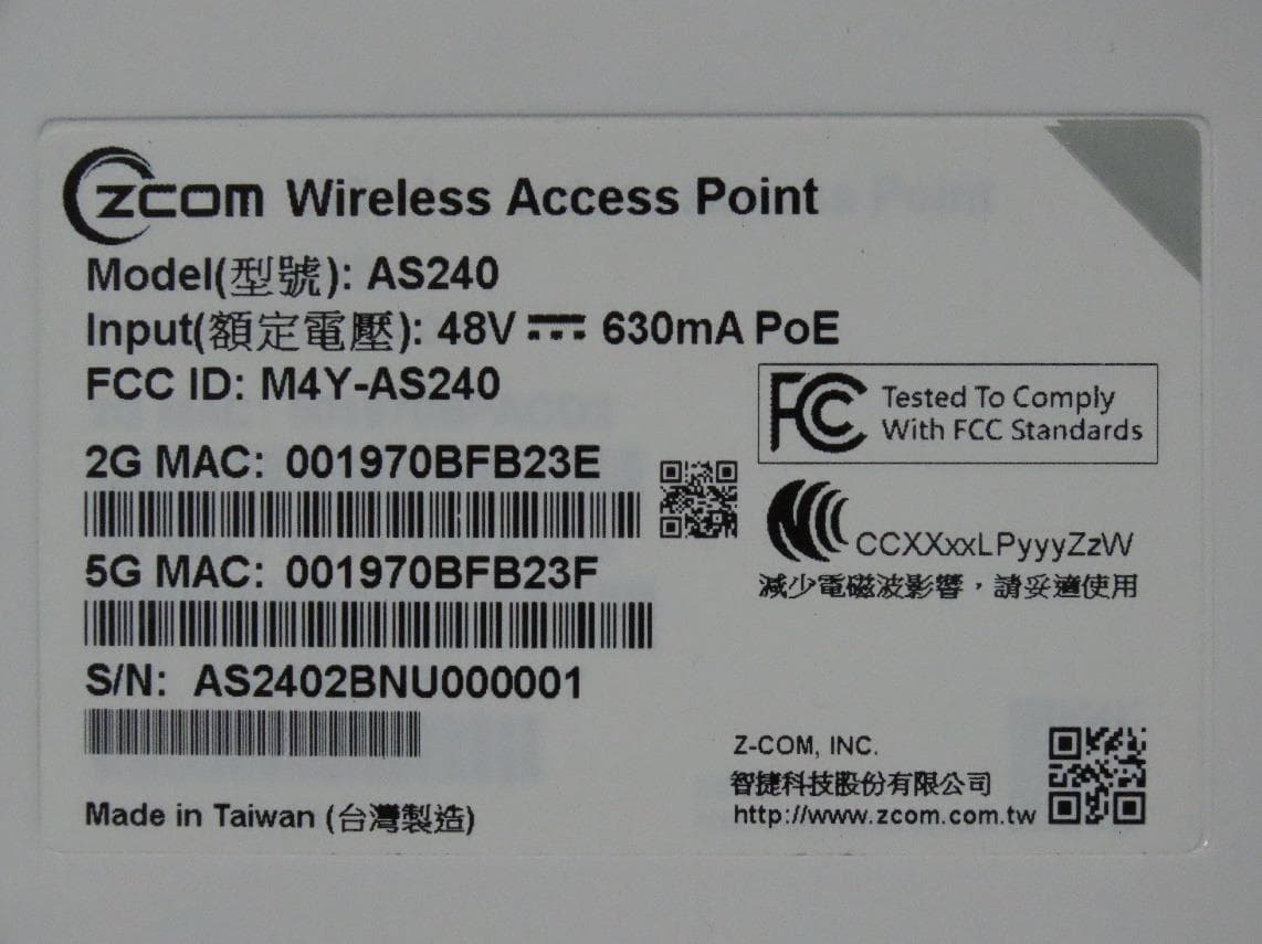
M4Y-AS240
Dec 13, 2022802.11ax Access Point
Equipment Class
DTS - Digital Transmission System
M4Y-AC720M
Aug 14, 2022802.11ac Wireless LAN USB Module
Equipment Class
NII - Unlicensed National Information Infrastructure TX
M4Y-SP230
Feb 21, 2021802.11 ac Wave 2 Access Point
Equipment Class
NII - Unlicensed National Information Infrastructure TX
M4Y-SP220C02
Jan 21, 2020802.11ac Access Point
Equipment Class
NII - Unlicensed National Information Infrastructure TX
M4Y-SP220C03
Jan 20, 20205GHz 11ac Wireless Bridge
Equipment Class
NII - Unlicensed National Information Infrastructure TX