M4Y-03500Wireless LAN PCMCIA Card
Z Com Inc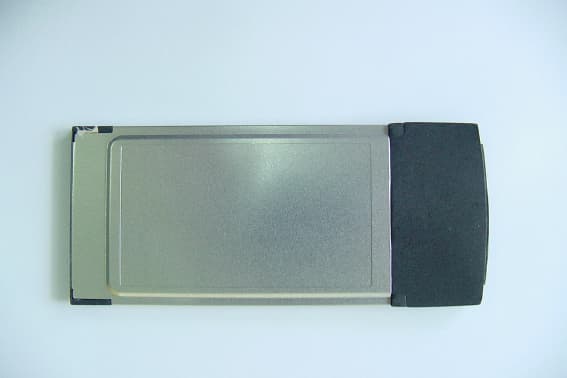
Click to zoom
Application Details
- Equipment Class
- DSS - Part 15 Spread Spectrum Transmitter
- Date of Grant
- Jul 25, 2002
- Application Purpose
- Original Equipment
- Date of Application
- Jun 20, 2002
- Equipment Note
- Wireless LAN PCMCIA Card
- Frequency Range
- 2412.00000000 - 2462.00000000
- Company
- Z Com Inc
- Country
- Taiwan
Documents & Files
Document Text
Text extracted from the exhibit documents filed with the FCC. Open a document above to read the original.
Users Manual
1 22Mbps Card BUS Wireless LAN PC Card Quick Start Guide I. Network Configuration 22Mbps Card BUS wireless LAN adapter is a 22Mbps Card BUS wireless LAN adapter. It fully supports Wireless networking under Windows 98/ME/NT/2000/XP. ® 22Mbps Card BUS wireless LAN adapter can be operated in Ad-Hoc or Infrastructure network configurations. Ad-Hoc mode allows 22Mbps Card BUS wireless LAN adapter. users to join a Basic Service Set (i.e., peer-to-peer mode, without access point). Infrastructure mode allows 22Mbps Card BUS wireless LAN adapter users to join an Extended Basic Service Set (i.e., connect to an Access Point) II. Package Content 22Mbps Wireless PC Card.............................................................................. x 1 Quick Installation Guide.................................................................................x 1 Product CD-ROM ........................................................................................x 1 III. Installation of the 22Mbps Wireless LAN PCMCIA Card under Windows XP 1. Insert the 22Mbps Card BUS wireless LAN adapter. into the PCMCIA slot on your notebook and start Windows. Windows will auto-detect the Wireless LAN PCMCIA Card and a “Found New Hardware Wizard” window will show up. 2. Select “Install from a list or specific (Advanced)” and insert the Product CD-ROM into the CD-ROM drive. Specify the location where the driver is placed. Click on Next to install the driver. 3. The windows will find “22Mbps Wireless LAN PC Card”. Click on Next to continue. 4. Click Finish to complete the installation. Infrastructure Ad-hoc Wired Wireless Access Point 2 After installing the Wireless LAN PC Card, the Windows XP will display a “Wireless Network Connection # ” message. Click on the message and the “Automatic Wireless Network Configuration” will then appear automatically and allow users to connect to an available wireless infrastructure network (Access Point), shown as follows: You may click the Advanced button to make advanced configuration for the 22Mbp Wireless LAN PC Card, shown as below. 3 For more information on using the Automatic Wireless Network Configuration please refer to Windows XP Help file. However, the WLAN Utility, which came with the Wireless LAN PC Card, provides you more tools to configure the 22Mbps Wireless LAN PC Card and to monitor the wireless connection. For more information on installing and using the WLAN utility, please refer to the following sections “Installation of the Wireless LAN Utility” and “Usage of the WLAN Utility”. Note: To use the WLAN utility under Windows XP, you need to disable the Automatic Wireless Network Configuration first. Steps are described as follows: n Right click the Network Connections icon. Select Properties. n Go to the Wireless Networks. n Uncheck the “Use Windows to configure my wireless network settings” check box and click the OK button (see the above picture). Installation of the 22Mbps Wireless LAN PCMCIA Card under Windows 2000 1. Insert the 22Mbps Wireless LAN PCMCIA Card into the PCMCIA slot on your notebook and start Windows. Windows will auto-detect the Wireless LAN PCMCIA Card and a “Found New Hardware Wizard” window will show up. Click Next to proceed. 2. Select “Search for a suitable driver for my device (recommended)”. Insert the Product CD-ROM into the CD-ROM drive. Specify the location where the driver is placed. Click on Next to install the driver. 3. The windows will find “22Mbps Wireless LAN PCMCIA Card”. Click on Next to continue. 4. Click Finish to complete the installation. Installation of the 22Mbps Wireless LAN PCMCIA Card under Windows NT 1. Insert the 22Mbps Wireless LAN PCMCIA Card into the PCMCIA slot on your notebook and start Windows. 2. From the desktop, select “Control Panel”, double-click Network, go to the Adapters tab, and then click the Add button. 3. Windows NT will present a list of all its supported adapters. Click Have Disk to continue. 4. Windows NT will ask for the path containing the 22Mbps Wireless PC Card Windows NT drivers. Insert the Product CD-ROM into the CD-ROM drive, and then choose the location where it is placed. Click OK to continue. 5. The Windows will find “22Mbps Wireless LAN PCMCIA Card” and then copy the necessary files into the system. Click OK to finish the installation. Restart your PC. 4 Installaton of the 22Mbps Wireless LAN PCMCIA Card under Windows 98/ME 1. Insert the 22Mbps Wireless LAN PCMCIA Card into the PCMCIA slot on your notebook and start Windows. Windows will auto-detect new hardware and will display an “Add New Hardware Wizard” window. 2. Select “Search for the best driver for your device (recommended)”. Insert the Product CD-ROM into the CD-ROM drive. Specify the location where the driver is placed. Click on Next to install the driver. 3. The Windows will find “22Mbps Wireless LAN PCMCIA Card”. Click on Next to continue. 4. Once the [Please insert the disk labeled “Windows 98/ME CD-ROM”, and then click OK] window appears, enter the path corresponding to the appropriate drives and click OK. Usually these files can be found at C:Windows or C:Windows\system. 5. Click Finish to complete the installation. Restart Windows. IV. Installation of the WLAN Utility 1. Insert the Product CD-ROM again. 2. Go to the utility folder and run setup.exe. 3. Follow the on-screen instructions to install the WLAN Utility. 4. Upon completion, go to Program Files and run the WLAN Utility. The utility interface will then appear and at the same time its icon appears in the System Tray in the bottom right corner of your task bar. V. Usage of the WLAN Utility The WLAN Utility consists of window with 5 items for you to monitor and configure the 22Mbps Wireless LAN PC Card: Configuration, Loop Back, AP Browser, Site Survey and About. Configuration: The Configuration item allows you to modify the configuration parameters for the 22Mbps Wireless LAN PC Card such as Profile, Network Type, Channel, Transmit Rate, ESSID, WEP, RTS/CTS, Fragment…
Text truncated - open the document above for the full version.
Users Manual
1 22Mbps Card BUS Wireless LAN PC Card Quick Start Guide I. Network Configuration 22Mbps Card BUS wireless LAN adapter is a 22Mbps Card BUS wireless LAN adapter. It fully supports Wireless networking under Windows 98/ME/NT/2000/XP. ® 22Mbps Card BUS wireless LAN adapter can be operated in Ad-Hoc or Infrastructure network configurations. Ad-Hoc mode allows 22Mbps Card BUS wireless LAN adapter. users to join a Basic Service Set (i.e., peer-to-peer mode, without access point). Infrastructure mode allows 22Mbps Card BUS wireless LAN adapter users to join an Extended Basic Service Set (i.e., connect to an Access Point) II. Package Content 22Mbps Wireless PC Card.............................................................................. x 1 Quick Installation Guide.................................................................................x 1 Product CD-ROM ........................................................................................x 1 III. Installation of the 22Mbps Wireless LAN PCMCIA Card under Windows XP 1. Insert the 22Mbps Card BUS wireless LAN adapter. into the PCMCIA slot on your notebook and start Windows. Windows will auto-detect the Wireless LAN PCMCIA Card and a “Found New Hardware Wizard” window will show up. 2. Select “Install from a list or specific (Advanced)” and insert the Product CD-ROM into the CD-ROM drive. Specify the location where the driver is placed. Click on Next to install the driver. 3. The windows will find “22Mbps Wireless LAN PC Card”. Click on Next to continue. 4. Click Finish to complete the installation. Infrastructure Ad-hoc Wired Wireless Access Point 2 After installing the Wireless LAN PC Card, the Windows XP will display a “Wireless Network Connection # ” message. Click on the message and the “Automatic Wireless Network Configuration” will then appear automatically and allow users to connect to an available wireless infrastructure network (Access Point), shown as follows: You may click the Advanced button to make advanced configuration for the 22Mbp Wireless LAN PC Card, shown as below. 3 For more information on using the Automatic Wireless Network Configuration please refer to Windows XP Help file. However, the WLAN Utility, which came with the Wireless LAN PC Card, provides you more tools to configure the 22Mbps Wireless LAN PC Card and to monitor the wireless connection. For more information on installing and using the WLAN utility, please refer to the following sections “Installation of the Wireless LAN Utility” and “Usage of the WLAN Utility”. Note: To use the WLAN utility under Windows XP, you need to disable the Automatic Wireless Network Configuration first. Steps are described as follows: n Right click the Network Connections icon. Select Properties. n Go to the Wireless Networks. n Uncheck the “Use Windows to configure my wireless network settings” check box and click the OK button (see the above picture). Installation of the 22Mbps Wireless LAN PCMCIA Card under Windows 2000 1. Insert the 22Mbps Wireless LAN PCMCIA Card into the PCMCIA slot on your notebook and start Windows. Windows will auto-detect the Wireless LAN PCMCIA Card and a “Found New Hardware Wizard” window will show up. Click Next to proceed. 2. Select “Search for a suitable driver for my device (recommended)”. Insert the Product CD-ROM into the CD-ROM drive. Specify the location where the driver is placed. Click on Next to install the driver. 3. The windows will find “22Mbps Wireless LAN PCMCIA Card”. Click on Next to continue. 4. Click Finish to complete the installation. Installation of the 22Mbps Wireless LAN PCMCIA Card under Windows NT 1. Insert the 22Mbps Wireless LAN PCMCIA Card into the PCMCIA slot on your notebook and start Windows. 2. From the desktop, select “Control Panel”, double-click Network, go to the Adapters tab, and then click the Add button. 3. Windows NT will present a list of all its supported adapters. Click Have Disk to continue. 4. Windows NT will ask for the path containing the 22Mbps Wireless PC Card Windows NT drivers. Insert the Product CD-ROM into the CD-ROM drive, and then choose the location where it is placed. Click OK to continue. 5. The Windows will find “22Mbps Wireless LAN PCMCIA Card” and then copy the necessary files into the system. Click OK to finish the installation. Restart your PC. 4 Installaton of the 22Mbps Wireless LAN PCMCIA Card under Windows 98/ME 1. Insert the 22Mbps Wireless LAN PCMCIA Card into the PCMCIA slot on your notebook and start Windows. Windows will auto-detect new hardware and will display an “Add New Hardware Wizard” window. 2. Select “Search for the best driver for your device (recommended)”. Insert the Product CD-ROM into the CD-ROM drive. Specify the location where the driver is placed. Click on Next to install the driver. 3. The Windows will find “22Mbps Wireless LAN PCMCIA Card”. Click on Next to continue. 4. Once the [Please insert the disk labeled “Windows 98/ME CD-ROM”, and then click OK] window appears, enter the path corresponding to the appropriate drives and click OK. Usually these files can be found at C:Windows or C:Windows\system. 5. Click Finish to complete the installation. Restart Windows. IV. Installation of the WLAN Utility 1. Insert the Product CD-ROM again. 2. Go to the utility folder and run setup.exe. 3. Follow the on-screen instructions to install the WLAN Utility. 4. Upon completion, go to Program Files and run the WLAN Utility. The utility interface will then appear and at the same time its icon appears in the System Tray in the bottom right corner of your task bar. V. Usage of the WLAN Utility The WLAN Utility consists of window with 5 items for you to monitor and configure the 22Mbps Wireless LAN PC Card: Configuration, Loop Back, AP Browser, Site Survey and About. Configuration: The Configuration item allows you to modify the configuration parameters for the 22Mbps Wireless LAN PC Card such as Profile, Network Type, Channel, Transmit Rate, ESSID, WEP, RTS/CTS, Fragment…
Text truncated - open the document above for the full version.
Cover Letter(s)
From: ckc [[email protected]] Sent: Monday, June 17, 2002 8:44 PM To: Mike Kuo Subject: Re: Z-COM, INC., FCC ID:M4Y-03500, AN02T2053 Hello! Mike, Attached please find the revised information for RF safety. But I can not understand why the EIRP I provided is not EIRP? As using a signal generator connected to a HORN antenna and transmit the power to gain the same radiated level on measurement instrument (SA) as the EUT's. The EIRP is a method of substitutive measurement. However, only nerrow band SG is availible, so we can only use the RBW of 1MHz to measure both of the signals of EUT and SG. So, the EIRP data provided in last e-mail, I just want to show you we use the RBW at 1MHz. Of course, it can be calculated to wideband value (total channel power): nerrow band value + 10log(emission BW/measurenebt BW) So, the result will be: CH01: 5.2 dBm / MHz + 10.8dB = 16.0 dBm CH07: 4.5 dBm / MHz + 10.8dB = 15.3 dBm CH11: 3.6 dBm / MHz + 10.9dB = 14.5 dBm If you have further questions, please let me know. Best regards, K. C. ----- Original Message ----- From: Mike Kuo To: 'ckc' Sent: Tuesday, June 18, 2002 10:36 AM Subject: RE: Z-COM, INC., FCC ID:M4Y-03500, AN02T2053 Hi K.C.: Question #9: In the revised RF exposure warning statement, you specified 20 cm separation distance. As I indicated in my question #1, this device when used with notebook computer, the end user can not maintain 20cm separation distance. Please change this separation distance from 20cm to 2.5cm and provide revised RF exposure statement. Question #10: The readings that you provided in addressing question #3 are not EIRP ( fundamental ) at low ,middle and high channels. Please provide EIRP readings. Best Regards Mike Kuo -----Original Message----- From: ckc [mailto:[email protected]] Sent: Monday, June 17, 2002 3:32 AM To: Mike Kuo Subject: Re: Z-COM, INC., FCC ID:M4Y-03500, AN02T2053 Dear Mike, Sorry fir the delay. I am going to clear all projects in my hands. Please find below for our reply to your questions: Question #1: This device is tested and to be used with laptop computer. The end user will not able to maintain 20cm away from all person. The RF exposure statement indicates in the user manual is not applicable to laptop computer usage. Please revise RF exposure warning statement. ANS.: Please find attached file regarding the warning statement for RF exposure. This will be added into the user's manual. (File name: Information.pdf) Question #2: Please provide antenna conducted spurious emission up to 10th harmonic for low, middle and high channel. ANS.: Attached please find the plots for conducted spuious emissions. (File name: XI-350-Conducted.pdf) Question #3: Per TCB RF review procedure, this device can only be certified as portable transmitter device operates at more than 2.5cm from a person's body with the peak conducted and peak radiated (EIRP) output not exceeding 50mW for 2.4GHz band. Since the highest reported antenna conducted output power is 16.9dBm ( 48.98mW) which is very near TCB limitations. Please provide EIRP measurement on low, middle and high channel. ANS.: For the antenna used with this transmitter has a typical gain of 0dBi, the radiated power is still under TCB limitation. The highest EIRP measurement is as follows: As referring to the nerrow band signal from SG, the EIRP on peak point of each channel: CH01: 5.2 dBm / MHz CH07: 4.5 dBm / MHz CH11: 3.6 dBm / MHz Question #4: What is the antenna gain in dBi ? ANS.: The antenna used with this transmitter is integral PCB type. The typical gain is 0dBi. Question #5: Please provide additional radiated spurious emission with high channel at restricted frequency of 2483.5MHz. ANS.: please find attachment for the radiated measurement data. (file name: edge.pdf) Question #6: Internal photos are listed as one of confidential document. Please remove this item from your request. It is FCC policy not to grant internal photos as confidential document. ANS.: Sure, please remove it for us. Question #7: Please provide a detail operational description to demonstrate this device complied with the definition of direct sequence spread spectrum. ANS.: PLS find the attachment for the description of spread spectrum IC. (File name : ti_acx100.pdf) Question #8: Please redo Mpe evaluation by using the separation distance as 2.5cm. ANS.: Please find the attachment for the required test data. (file name: MPE -retest.pdf) If you need any further information, please let me know as soon as possible. Best regards, K. C. Chen ----- Original Message ----- From: Mike Kuo To: K. C. (E-mail) ; Will Yauo (E-mail) ; Will Yauo-Personal (E-mail) Sent: Tuesday, June 11, 2002 8:01 AM Subject: FW: Z-COM, INC., FCC ID:M4Y-03500, AN02T2053 -----Original Message----- From: CERTADM Sent: Monday, June 10, 2002 5:00 PM To: '[email protected]' Subject: Z-COM, INC., FCC ID:M4Y-03500, AN02T2053 Notice_content ------------- Question #1: This device is tested and to be used with laptop computer. The end user will not able to maintain 20cm away from all person. The RF exposure statement indicates in the user manual is not applicable to laptop computer usage. Please revise RF exposure warning statement. Question #2: Please provide antenna conducted spurious emission up to 10th harmonic for low, middle and high channel. Question #3: Per TCB RF review procedure, this device can only be certified as portable transmitter device operates at more than 2.5cm from a person's body with the peak conducted and peak radiated (EIRP) output not exceeding 50mW for 2.4GHz band. Since the highest reported antenna conducted output power is 16.9dBm ( 48.98mW) which is very near TCB limitations. Please provide EIRP measurement on low, middle and high channel. Question #4: What is the antenna gain in dBi ? Question #5: Please provide additional radiated spurious emission with high channel at restricted frequency of 2483.5MHz. Question #6: Internal photos are listed as one of confidential document. Please remove this item …
Text truncated - open the document above for the full version.
External Photos
ETC Report No. : ET91R-04-093-03 Sheet 1 of 4 Sheets FCC ID.: M4Y-03500 Rev. No 2.0 CONSTRUCTED PHOTOS of EUT Front View of EUT Rear View of EUT
ID Label/Location Info
REAR VIEW OF EUT 64mm 40mm 22 Mbps Wireless LAN PC Card FCC ID.: M4Y-03500 MADE IN TAIWAN This device complies with part 15 of the FCC Rules. Operation is subject to the following two conditions: (1) this device may not cause harmful interference and (2) this device must accept any interference received, including interference that may cause undesired operation. Model:XI-350
Internal Photos
ETC Report No. : ET91R-04-093-03 Sheet 2 of 4 Sheets FCC ID.: M4Y-03500 Rev. No 2.0 CONSTRUCTED PHOTOS of EUT Internal View of EUT Internal View of EUT ETC Report No. : ET91R-04-093-03 Sheet 3 of 4 Sheets FCC ID.: M4Y-03500 Rev. No 2.0 CONSTRUCTED PHOTOS of EUT Component View of Main PCB Solder View of Main PCB
Operational Description
Key Benefits • Data rates: 1, 2, 5.5, 11, and 22 Mbit/s • Embedded ARM ® 7TDMI CPU and RAM • Supports all IEEE 802.11b modulations • Supports CardBus, PCI, and USB 1.1 interfaces • Supports multiple radio topologies • Targets Wi-Fi TM systems compliance • Processing gain up to 15 dB • Multipath delay spread tolerance > 250 ns • Supports JTAG boundary scan Product Bulletin Spread Spectrum Processor with Medium Access Control THE WORLDLEADERINDSP ANDANALOG Host System PCI/CardBus/USB 1.1 Adapter Card Host CPU Applications OS Driver API NDIS Host System Bus Hardware Host RAM PCI/CardBus/ USB 1.1 Host Interface Host Interface Hardware Embedded CPU Local Internal RAM Medium Access Controller (MAC) Baseband Processor (PHY) Radio ACX100 Flash External RAM EEPROM LEDs 44-Mhz Clock Antenna IEEE 802.3 NIC Local Bus IEEE 802.3 Optional: AP Applications Only IEEE 802.3 NIC IEEE 802.3 ACX100 System Block Diagram The ACX100 single-chip wireless local area network (WLAN) medium access controller (MAC) with an IEEE 802.11b-compliant spread spectrum baseband processor from Texas Instruments combines high-performance with robust functionality. In addition to the MAC and baseband processor, the ACX100 integrates an ARM ® 7TDMI RISC processor, as well as host and baseband interfaces. The ACX100 directly interfaces to a host and radio to provide a com- plete high-speed networking solution for OEM WLAN system providers. The ACX100 complies with Wireless Ethernet Compatibility Alliance specifications to enhance and maintain Wi-Fi TM compliance in WLAN systems. The processor supports typical applications such as: • CardBus/PCI/mini-PCI WLAN adapters • High-speed WLAN access points • High-speed WLAN bridges • 2.4-GHz WLAN systems • Portable notebook/PDA computer links • Part 15-compliant radio links • Portable bar code scanners/POS terminals. The IEEE 802.11-compliant MAC supports high data rates by implementing real-time functions in hardware. The embedded ARM 7TDMI RISC processor manages the host interface in addition to other high level functions. The ARM 7TDMI can also override many hardware functions. The ACX100 host interface directly supports 32-bit CardBus and PCI interfaces. For added flexibility in host connectivity, the ACX100 also supports USB 1.1 interfaces. In access point (AP) applications, the ACX100 sup- ports IEEE 802.3 network inter- face cards (NIC) for Ethernet connectivity. The host interface supports DMA transfers between host memory and ACX100 embedded RAM in ACX100 master and slave modes. The ACX100 features embedded RAM for code execu- tion and data buffering. It dynami- cally allocates transmit and receive memory for efficient memory usage. The MAC/base- band hardware parses received frames independently of the embedded CPU. An external memory interface supports addi- tional RAM and Flash devices. The MAC hardware can directly generate ACK, RTS, CTS, probe response and beacon pack- ets. It also provides wired equiva- lent privacy (WEP). The MAC can perform encryption and decryp- tion on frames using keys of up to 256 bits in length. The ACX100 radio interface includes dual 8-bit, 22-MHz analog- to-digital converters (ADC) for the I and Q receive inputs, as well as dual 10-bit, 44-MHz digital-to- analog converters (DAC) for the I and Q transmit outputs. The radio interface also features transmit gain control and receive auto- matic gain control (AGC), which are programmable and support a variety of 2.4-GHz radios. The ACX100 receiver also implements antenna diversity and performs clear channel assessment (CCA). While operating under dense multipath or noisy environments, the baseband receiver increases performance by means of sophis- ticated decoding algorithms that minimize the need for retransmis- sion. The ACX100 has a multipath delay spread tolerance greater than 250 ns. TI provides two package options for the ACX100: 208-pin Plastic Quad Flat Pack (PQFP) and the 257-pin BGA. The ACX100 requires supply voltages of 1.8 V and 3.3 V, and features 3.3-V tolerant I/Os. The ACX100 also provides 16 general-purpose I/Os for interfacing flexibility. Setting the high-performance standard Texas Instruments’ enhancement of the IEEE 802.11b standard delivers the most aggressive data rates available in the 2.4 GHz WLAN market. By employing advanced forward error correc- tion (FEC) and modulation tech- niques, the ACX100 achieves much higher performance levels than competing solutions. The ACX100’s proprietary application of Packet Binary Convolutional Code (PBCC TM ) technology pro- vides data rates up to 22 Mbit/s in 8.5 dB of signal-to-noise response (SNR) with a packet error rate (PER) of 10 -2 . The ACX100 is compatible with existing 1- and 2-Mbit/s IEEE 802.11 direct sequence products. In addition to 5.5-, 11-, and 22- Mbit/s PBCC modes, the ACX100 operates at 5.5 and 11 Mbit/s in Complementary Code Keying (CCK) modes. The ACX100 supports long and short physical layer convergence protocol (PLCP) preambles according to the IEEE 802.11b high-rate specification. The ACX100 PBCC modes require 4 dB less SNR in AWGN than the CCK modes to achieve a PER of 10 -2 . The PBCC modes essentially double the data rates of the CCK modes at any noise or multipath distortion level. For more information For more information on how the ACX100 can give you a competi- tive advantage in your market, visit our web site at: www.ti.com/sc/wirelessnetworking © 2001 Texas Instruments Incorporated Printed on recycled paper. Important Notice:The products and services of Texas Instruments and its subsidiaries described herein are sold subject to TI’s standard terms and conditions of sale. Customers are advised to obtain the most current and complete information about TI products and services before placing orders. TI assumes no liability for applications assist- ance, customer’s applications or product designs, software performance, or infringe- ment of patents. The publication of informa- tion regarding any other company…
Text truncated - open the document above for the full version.
RF Exposure Info
FCC INFORMATION The Federal Communication Commission Radio Frequency Interference Statement includes the following paragraph: The equipment has been tested and found to comply with the limits for a Class B Digital Device, pursuant to part 15 of the FCC Rules. These limits are designed to provide reasonable protection against harmful interference in a residential installation. This equipment generates, uses and can radiate radio frequency energy and, if not installed and used in accordance with the instruction, may cause harmful interference to radio communication. However, there is no grantee that interference will not occur in a particular installation. If this equipment dose cause harmful interference to radio or television reception, which can be determined by turning the equipment off and on , the user is encouraged to try to correct the interference by one or more of the following measures: --Reorient or relocate the receiving antenna. --Increase the separation between the equipment and receiver. --Connect the equipment into an outlet on a circuit different from that to which the receiver is connected. --Consult the dealer or an experienced radio/TV technician for help. Notice: 1. The Changes or modification not expressly approved by the party responsible for compliance could void the user’s authority to operate the equipment. Warning : To comply with FCC RF exposure requirements for mobile transmitting devices, a minimum separation distance of 2.5 cm must be maintained between the antenna and all persons during device operation. Canada IC Information Operation is subject to the following two conditions: (1) this device may not cause interference, and (2) this device must accept any interference, including interference that may cause undesired operation of the device. To reduce potential radio interference to other users, the antenna type and its gain should be so chosen that the equivalent isotropically radiated power (EIRP) is not more than that required for successful communication. The term “IC:” before the certification/registration number only signifies that the Industry Canada technical specifications were met.
RF Exposure Info
ETC Report No. : ET91R-04-093-03 FCC ID.: M4Y-03500 Supplement for MPE testing data. Operation Mode: Maximum Data Transmitting Rate Transmitting Frequency : 2400 to 2483.5 MHz Rated Maximum Output Power: 17 dBm Measured Output Peak Power: 16.9dBm@2412MHz, 16.4dBm@2442MHz, 15.2dBm@2462MHz Test Date: June 14, 2002Temperature: 26 Humidity: 65% Measured Frequency MHz Measured @ 2.5cm mW/cm 2 Probe Factor Maximum Result @2.5cm mW/ cm 2 MPE Limt mW/cm 2 2412.000.870.820.71 1.0 2442.000.820.820.67 1.0 2462.000.780.820.64 1.0 Note : 1. Remark “---” means that the emission level is too low to be measured (the precise accuracy of the measurement system is 0.01 mW/ cm 2 ). 2. Value 0.82 is a corrected factor of measurement system. 3. Result = Value Measured X Corrected Factor. 4. The measurement was performed under the condition of fixed the emission frequency to get the most extreme MPE. EquipmentManufacturerModel No.Next Cal. Due Survey MeterNarda8712Jan. 30, 2003 ProbeNarda8721DJan. 30, 2003
RF Exposure Info
Rev. No 2.0 RF Maximum Permissible Exposure Measurement Report of E.U.T. : 22Mbps Wireless LAN PC Card FCC ID. : M4Y-03500 MODEL : XI-350 for APPLICANT : Z-COM, INC. ADDRESS : 7F-2, NO. 9, PROSEPERITY 1ST RD., SCIENCE- BASED INDUSTRIAL PARK, HSINCHU, TAIWAN, R.O.C. Test Performed by ELECTRONICS TESTING CENTER, TAIWAN NO. 34, LIN 5, DING FU TSUN, LINKOU HSIANG, TAIPEI HSIE, TAIWAN, R.O.C. Tel:(02)26023052, 26023054 Fax:(02)26010910 Report Number : ET91R-04-093-03 ETC Report No. : ET91R-04-093-03 FCC ID.: M4Y-03500 Rev. No 2.0 TEST REPORT CERTIFICATION Applicant : Z-COM, INC. 7F-2, NO. 9, PROSEPERITY 1ST RD., SCIENCE-BASED INDUSTRIAL PARK, HSINCHU, TAIWAN, R.O.C. Manufacturer : Z-COM, INC. 7F-2, NO. 9, PROSEPERITY 1ST RD., SCIENCE-BASED INDUSTRIAL PARK, HSINCHU, TAIWAN, R.O.C. Description of EUT : a) Type of EUT : 22Mbps Wireless LAN PC Card b) Trade Name : Z-COM c) Model No. : XI-350 d) Power Supply : From Notebook PC Regulation Applied : IEEE C95.1-1991, FCC 47 CFR Part 1 and Part 2 I HEREBY CERTIFY THAT: The data shown in this report were made in accordance with the procedures given in IEEE C95.1, and the energy emitted by the device was founded to be within the limits applicable. I assume full responsibility for accuracy and completeness of these data. Note: 1. The result of the testing report relates only to the item tested. 2. The testing report shall not be reproduced expect in full, without the written approval of ETC. Issued Date : Jan. 07, 2003 Test Engineer : ( S. S. Liou ) Approve & Authorized Signer : Will Yauo, Manager EMC Detp. II of ELECTRONICS TESTING CENTER, TAIWAN ETC Report No. : ET91R-04-093-03 FCC ID.: M4Y-03500 Rev. No 2.0 Table of Contents Page 1 GENERAL INFORMATION 1 1.1 Product Description........................................................................................................................1 1.2 Characteristics of Device................................................................................................................1 1.…
Text truncated - open the document above for the full version.
Contact Information
Applicant
Jeff jiang(R&D DIV Director)
Test Firm
Electronics Testing Center, TaiwanWill Yauo
Technical Specifications
| # | Rule Parts | Frequency Range | Power Output |
|---|---|---|---|
| 1 | 15C | 2.41 GHz - 2.46 GHz | 48.98 mW |
Other Applications from Z Com Inc
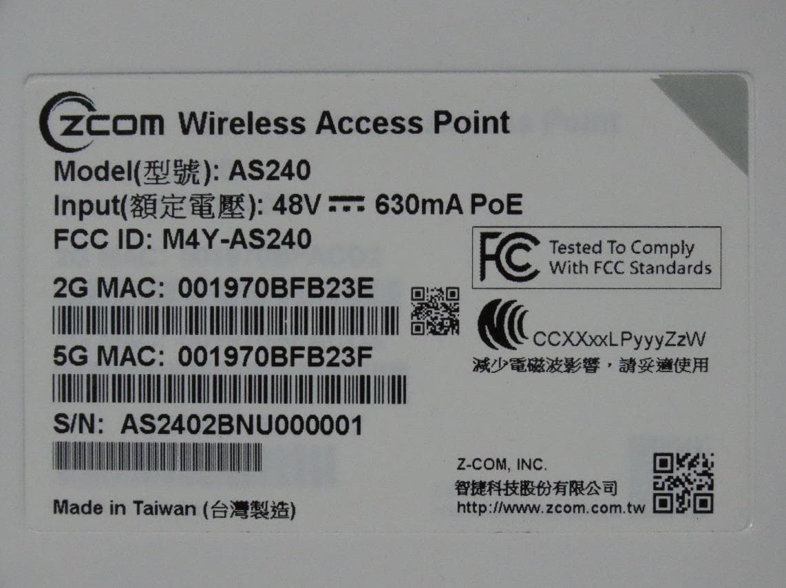
M4Y-AS240
Dec 13, 2022802.11ax Access Point
Equipment Class
DTS - Digital Transmission System
M4Y-AC720M
Aug 14, 2022802.11ac Wireless LAN USB Module
Equipment Class
NII - Unlicensed National Information Infrastructure TX
M4Y-SP230
Feb 21, 2021802.11 ac Wave 2 Access Point
Equipment Class
NII - Unlicensed National Information Infrastructure TX
M4Y-SP220C02
Jan 21, 2020802.11ac Access Point
Equipment Class
NII - Unlicensed National Information Infrastructure TX
M4Y-SP220C03
Jan 20, 20205GHz 11ac Wireless Bridge
Equipment Class
NII - Unlicensed National Information Infrastructure TX