M4Y-0X196011 Mbps Wireless LAN PCI Adapter
Z Com Inc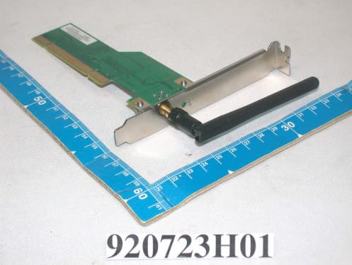
Click to zoom
Application Details
- Equipment Class
- DTS - Digital Transmission System
- Date of Grant
- Sep 04, 2003
- Application Purpose
- Original Equipment
- Date of Application
- Sep 04, 2003
- Equipment Note
- 11 Mbps Wireless LAN PCI Adapter
- Frequency Range
- 2412.00000000 - 2462.00000000
- Company
- Z Com Inc
- Country
- Taiwan
Documents & Files
Document Text
Text extracted from the exhibit documents filed with the FCC. Open a document above to read the original.
Users Manual
11Mbps Wireless LAN PCI Adapter Date of Issue: Aug. 20th, 2003 Technical Support The firmware version of the Wireless LAN PCI Card is displayed on the utility About window. Users could download the most recent software version from the supplier’s web site or refer to the selling contact for the latest software information. If you have difficulty resolving the problem while installing or using the 802.11b Wireless LAN PCI Card, please contact the supplier for support. About This Manual 802.11b Wireless LAN PCI Card User Manual was first released on August, 2003. The manual includes procedures for the setup of the 802.11b Wireless LAN PCI Card under Windows XP, Windows 2000, Windows 98SE or Windows ME. Take a moment to read through this manual and familiarize yourself with wireless technology. FCC Information This device, IEEE 802.11b WLAN PCI Card, complies with Part 15 of the FCC Rules. Operation is subject to the following two conditions: (1) this device may not cause harmful interference, and (2) this device must accept any interference received; including interference that may cause undesired operation. Federal Communications Commission (FCC) Statement This Equipment has been tested and found to comply with the limits for a Class B digital device, pursuant to Part 15 of the FCC rules. These limits are designed to provide reasonable protection against harmful interference in a residential installation. This equipment generates, uses and can radiate radio frequency energy and, if not installed and used in accordance with the instructions, may cause harmful interference to radio communications. However, there is no guarantee that interference will not occur in a particular installation. If this equipment does cause harmful interference to radio or television reception, which can be determined by turning the equipment off and on, the user is encouraged to try to correct the interference by one or more of the following measures: Reorient or relocate the receiving antenna. Increase the separation between the equipment and receiver. Connect the equipment into an outlet on a circuit different from that to which the receiver is connected. Consult the dealer or an experienced radio/TV technician for help. Warning: Changes or modifications to this unit not expressly approved by the party responsible for compliance could void the user authority to operate the equipment. Tested to comply with FCC standard. FOR HOME OR OFFICE USE. FCC RF Radiation Exposure Statement: 1. This equipment complies with FCC RF radiation exposure limits set forth for an uncontrolled environment, under 47 CFR 2.1093 paragraph (d)(2). This equipment should be installed and operated with minimum distance 20cm between the radiator & your body. 2. This Transmitter must not be co-located or operating in conjunction with any other antenna or transmitter. The IEEE 802.11b WLAN PCI Card has been tested to the FCC exposure requirements (Specific Absorbtion Rate). Table of Contents Chapter 1 About Wireless LAN PCI Card ..........................................1 1-1 Features and Benefits ................................................................................... 1 1-2 Applications.................................................................................................. 2 1-3 Product Kit ................................................................................................... 3 1-4 About Wireless LAN PCI Card LED Indicators .......................................... 3 Chapter 2 Getting Started .....................................................................4 2-1 Before Installation ........................................................................................ 4 2-2 Insert the 802.11b Wireless LAN PCI Card................................................. 5 Chapter 3 Install Driver for Windows..................................................................6 3-1 Set up Wireless LAN PCI Card for Windows XP ......................................... 6 3-2 Set up Wireless LAN PCI Card for Windows 2000.................................... 11 3-3 Set up Wireless LAN PCI Card for Windows 98SE/ ME ........................... 15 Chapter 4 Configure the Wireless LAN PCI Card ...........................19 4-1 Install the WLAN Utility ............................................................................. 19 4-2 Use the WLAN Utility ................................................................................. 23 4-2-1 Configuration .......................................................................................................23 4-2-2 Site Survey ............................................................................................................29 4-2-3 About ....................................................................................................................30 Limited Warranty ................................................................................31 -1- About Wireless LAN PCI Card 1 The 802.11b Wireless LAN PCI Card is a standard PCI adapter that fits into any standard PCI slot in a desktop. The 802.11b Wireless LAN PCI Card is an enhanced high-performance, that supports high-speed wireless networking at home, or at office. 802.11b Wireless LAN PCI Card is able to communicate with any 802.11b and 802.11g compliant products. 1-1 Features and Benefits 1. Fully IEEE 802.11b compatible. 2. Supports 1, 2, 5.5, and up to11 Mbps data rate. 3. Working range up to 800 ft. in an open environment. 4. Seamless connectivity to wired Ethernet and PC network LAN’s augments existing networks quickly and easily. 5. Greater flexibility to locate or move networked PCs. 6. Wireless connection without the cost of cabling. 7. Easy to install and user friendly, just Plug and Play (PnP). 8. Lower power consumption. 9. Supports a variety of operating systems (Win98SE/ME/2000/XP) 10. 64-bit and 128-bit WEP encryption capable. 11. Direct Sequence Spread Spectrum (DSSS) techno…
Text truncated - open the document above for the full version.
Cover Letter(s)
[email protected] www.adt.com.tw ADVANCE DATA TECHNOLOGY CORPORATION FEDERAL COMMUNICATIONS COMMISSION DECLARATION OF CONFORMITY (DoC) FOR THE FOLLOWING EQUIPMENT: PRODUCT NAME : 11Mbps Wireless LAN PCI Adapter MODEL NO : XI-960 TRADE NAME : Z-Com IS HEREWITH CONFIRMED AND FOUND TO COMPLY WITH THE REQUIREMENTS OF CFR 47 PART 15 REGULATION. THE RESULTS OF ELECTROMAGNETIC EMISSION EVALUATION ARE SHOWN IN THE REPORT NO : D920723H01 THIS DEVICE COMPLIES WITH PART 15 OF THE FCC RULES. OPERATION IS SUBJECT TO THE FOLLOWING TWO CONDITIONS: (1) THIS DEVICE MAY NOT CAUSE HARMFUL INTERFERENCE AND, (2) THIS DEVICE MUST ACCEPT ANY INTERFERENCE RECEIVED, INCLUDING INTERFERENCE THAT MAY CAUSE UNDESIRED OPERATION. THE FOLLOWING LOCAL MANUFACTURER/IMPORTER IS RESPONSIBLE FOR THIS DECLARATION Manufacturer USA Local Representative Company name: Z-COM, INC. Company name: To be determined. Address: 7F-2, No.9. Prosperity RD. I , Science-Based Industrial Park Hsinchu, 300 Taiwan. Address: Contact Person: Beryl Lin Contact Person: Title: Product Manager Title: Tel/Fax: 03-577-7364/ 03-577-3359 Tel/Fax:
External Photos
Page 1 CONSTRUCTION PHOTOS OF EUT Antenna Model: ADA06-1K10000 Page 2 Antenna Model: SAW-0008A
ID Label/Location Info
(Fig. 1) FCC ID: FCC LABEL LOCATION The label will be permanently affixed at a conspicuous location on the device. Label
ID Label/Location Info
SCALE ECO NO.REVISIONAPP.DES.DATE TOLERANCE GRADE ( ) GRADE ABC LENGTH 60.050.080.20 0.080.100.30 0.100.150.40 0.200.300.80 6618 1850 50180 ~ ~ ~ ~ DRW.DES.CKD.RECKD.APP. MODELSHEET D W G N O . N V A 1 1 Z-Com, Inc. NAME PART NO. 1 UNITS GRADEANGLE M.M. TOLERANCE 1 1 0 . 2 XI-960 Label FCC NB XI-960 56-580001-00 Winda 920811 0.2 11Mbps Wireless LAN PCI Adapter MODEL:XI-960 30.00 mm 2 0 . 0 0 m m P A 0 1 1 5 Made in Taiwan56-580001-00 IEEE 802.11b PCI Adapter MODEL:XI-960 Made in Taiwan56-580001-00 Input Voltage:DC3.3V H/W REV:0.1 MAC Address:0060B3-123456 1234567891012 FCC ID: M4Y-0XI960 920820 : 1. : 50# 2. : 3. 4. 5. :+/-1mm 6. <=0.15mm() 7.NPA0049 NOTE : 1.Label Material:#50 SILVER POLYESTER 2.Glue Material:PET MAT POLYPROPYLENE 3.Label Color:SILVER 4.Font Color;BLACK
Internal Photos
Page 1 CONSTRUCTION PHOTOS OF EUT Antenna Model: ADA06-1K10000 Page 2 Page 3 Page 4 Page 5 Page 6 Page 7 Antenna Model: SAW-0008A Page 8 Page 9 Page 10
Operational Description
FCC ID: M4Y-0XI960 ADT No. 920723H01 Operational Description The transmitter of the EUT is powered by host equipment. The antennas are Dipole Antenna, antenna 1 with SMA Male RP connector and antenna 2 with SMA Reverse connector. The other instruction, please have a look at the users manual. DSSS Information This device is Direct Sequence Spread Spectrum, the data is mixed by pseudorandom code which is an orthogonal code. The mixed data is digital modulated by BPSK and QPSK technique depends on the data rates. The CCK coding is applied for increasing the data rate, and also the processing gain will be increased. The bit rates are 1,2,5.5,11Mbps, the symbol rates are 1,1,1.375,1.375Mbps, the chip rates are always 11Mbps. So, the Chip/symbol is 11,11,8 and 8 respectively. Although is higher bit rate, the processing gain is lower than 10, but the CCK coding used in higher bit rate will provide 2.2dB coding gain.
RF Exposure Info
FCC ID: M4Y-0XI960 Report No.: RF920723H01 ADT No. 920723H01 1 RF EXPOSURE REPORT REPORT NO.: RF920723H01 MODEL NO.: XI-960 ACCORDING: FCC Guidelines for Human Exposure IEEE C95.1 APPLICANT: Z-COM, INC. ADDRESS: 7F-2, No.9. Prosperity RD. I , Science-Based Industrial Park Hsinchu, 300 Taiwan ISSUED BY: Advance Data Technology Corporation LAB LOCATION: No. 81-1, Lu Liao Keng, 9 Ling, Wu Lung Tsuen, Chiung Lin Hsiang, Hsin Chu Hsien, Taiwan, R.O.C. Lab Code: 200376-0 FCC ID: M4Y-0XI960 Report No.: RF920723H01 ADT No. 920723H01 2 RF Exposure Measurement 1. Introduction In this document, we try to prove the safety of radiation harmfulness to the human body for our product. The limit for Maximum Permissible Exposure (MPE) specified in FCC 1.1310 is followed. The Gain of the antenna used in this product is measured in a Fully Anechoic Chamber (FAC) calibrated for antenna measurement in ADT, and also the maximum total power input to the antenna is measured. Through the Friis transmission formula and the maximum gain of the antenna, we can calculate the distance, away from the product, where the limit of MPE is reached. Although the Friis transmission formula is a far field assumption, the calculated result of that is an over-prediction for near field power density. We will take that as the worst case to specify the safety range. 2. RF Exposure Limit According to FCC 1.1310: The criteria listed in the following table shall be used to evaluate the environmental impact of human exposure to radio-frequency (RF) radiation as specified in 1.1307(b) LIMITS FOR MAXIMUM PERMISSIBLE EXPOSURE (MPE) Frequency Range (MHz) Electric Field Strength (V/m) Magnetic Field Strength (A/m) Power Density (mW/cm 2 ) Average Time (minutes) (A)Limits For Occupational / Control Exposures 300-1500......F/3006 1500-100,000......56 (B)Limits For General Population / Uncontrolled Exposure 300-1500......F/15006 1500-100,000......1.030 F = Frequency in MHz FCC ID: M4Y-0XI960 Report No.: RF920723H01 ADT No. 920723H01 3 3. Friis Formula Friis transmission formula : Pd = (Pout*G) / (4*pi*r 2 ) where Pd = power density in mW/cm 2 Pout = output power to antenna in mW G = gain of antenna in linear scale Pi = 3.1416 R = distance between observation point and center of the radiator in cm Pd is the limit of MPE, 1 mW/cm 2 . If we know the maximum Gain of the antenna and the total power input to the antenna, through the calculation, we will know the MPE value at distance 20cm. Ref. : David K. Cheng, Field and Wave Electromagnetics, Second Edition, Page 640, Eq. (11-133). 4. EUT Operating condition The software provided by Manufacturer enabled the EUT to transmit and receive data at lowest, middle and highest channel individually. 5. Classification The antenna of this product, under normal use condition, is at least 20cm away from the body of the user. Warning statement to the user for keeping at least 20cm or more separation distance with the antenna should be included in users manual. So, this device is classified as Mobile Device FCC ID: M4Y-0XI960 Report No.: RF920723H01 ADT No. 920723H01 4 6. Test Results 6.1 Antenna Gain The maximum Gain measured in Fully Anechoic Chamber are 2Bi or 1.58 (numeric). 6.2 Output Power Into Antenna & RF Exposure value at distance 20cm: Channel Channel Frequency (MHz) Output Power to Antenna (mW) Power Density (mW/cm 2 ) Limit of Power Density (mW/cm 2 ) 12412100.6930.031751.0 62437102.3290.032261.0 112462108.8930.034331.0
Test Report
FCC ID: M4Y-0XI960 Report No.: RF920723H011Issued: Jul. 31, 2003 ADT No. 920723H01 FCC TEST REPORT REPORT NO.: RF920723H01 MODEL NO.: XI-960 RECEIVED: Jul. 23, 2003 TESTED: Jul. 21 to 27, 2003 APPLICANT: Z-COM, INC. ADDRESS: 7F-2, No.9. Prosperity RD. I , Science-Based Industrial Park Hsinchu, 300 Taiwan ISSUED BY: Advance Data Technology Corporation LAB LOCATION: No. 81-1, Lu Liao Keng, 9 Ling, Wu Lung Tsuen, Chiung Lin Hsiang, Hsin Chu Hsien, Taiwan, R.O.C. This test report consists of 45 pages in total. It may be duplicated completely for legal use with the approval of the applicant. It should not be reproduced except in full, without the written approval of our laboratory. The client should not use it to claim product endorsement by CNLA, NVLAP or any government agencies. The test results in the report only apply to the tested sample. Lab Code: 200376-0 FCC ID: M4Y-0XI960 Report No.: RF920723H012Issued: Jul. 31, 2003 ADT No. 920723H01 Table of Contents 1CERTIFICATION......................................................................................................4 2SUMMARY OF TEST RESULTS...........................................................................5 3GENERAL INFORMATION....................................................................................6 3.1GENERAL DESCRIPTION OF EUT.....................................................................6 3.2DESCRIPTION OF TEST MODES.......................................................................7 3.3GENERAL DESCRIPTION OF APPLIED STANDARDS..................................7 3.4DESCRIPTION OF SUPPORT UNITS.................................................................8 4TEST TYPES AND RESULTS...............................................................................9 4.1CONDUCTED EMISSION MEASUREMENT......................................................9 4.1.1TEST INSTRUMENTS...............................................................................................9 4.1.2TEST PROCEDURES.............................................................................................10 4.1.3DEVIATION FROM TEST STANDARD...................................................................10 4.1.4TEST SETUP............................................................................................................11 4.1.5EUT OPERATING CONDITIONS............................................................................12 4.1.6TEST RESULTS.......................................................................................................13 4.2RADIATED EMISSION MEASUREMENT.........................................................15 4.2.1LIMITS OF RADIATED EMISSION MEASUREMENT............................................15 4.2.2TEST INSTRUMENTS.............................................................................................16 4.2.3TEST PROCEDURES.............................................................................................17 4.2.4DEVIATION FROM TEST STANDARD...................................................................17 4.2.5TEST SETUP...........................................................................................................18 4.2.6EUT OPERATING CONDITIONS............................................................................18 4.2.7TEST RESULTS.......................................................................................................19 4.36dB BANDWIDTH MEASUREMENT.................................................................23 4.3.1LIMITS OF 6dB BANDWIDTH MEASUREMENT....................................................23 4.3.2TEST INSTRUMENTS.............................................................................................23 4.3.3TEST PROCEDURE................................................................................................24 4.3.4DEVIATION FROM TEST STANDARD...................................................................24 4.3.5TEST SETUP...........................................................................................................24 4.3.6EUT OPERATING CONDITIONS............................................................................24 4.3.7TEST RESULTS.......................................................................................................25 4.4MAXIMUM PEAK OUTPUT POWER.................................................................29 4.4.1LIMITS OF MAXIMUM PEAK OUTPUT POWER MEASUREMENT......................29 4.4.2INSTRUMENTS........................................................................................................29 4.4.3TEST PROCEDURES.............................................................................................30 4.4.4TEST SETUP...........................................................................................................30 4.4.5EUT OPERATING CONDITIONS............................................................................30 FCC ID: M4Y-0XI960 Report No.: RF920723H013Issued: Jul. 31, 2003 ADT No. 920723H01 4.4.6TEST RESULTS.......................................................................................................31 4.4.7LIMITS OF POWER SPECTRAL DENSITY MEASUREMENT...............................32 4.4.8TEST INSTRUMENTS.............................................................................................32 4.4.9TEST PROCEDURE................................................................................................33 4.4.10DEVIATION FROM TEST STANDARD...................................................................33 4.4.11TEST SETUP...........................................................................................................33 4.4.12EUT OPERATING CONDITION...............................................................................33 4.4.13TEST RESULTS.......................................................................................................34 4.5BAND EDGES MEASUREMENT....................…
Text truncated - open the document above for the full version.
Test Setup Photos
FCC ID: M4Y-0XI960 Report No.: RF920723H0143Issued: Jul. 31, 2003 ADT No. 920723H01 5 PHOTOGRAPHS OF THE TEST CONFIGURATION CONDUCTED EMISSION TEST FCC ID: M4Y-0XI960 Report No.: RF920723H0144Issued: Jul. 31, 2003 ADT No. 920723H01 RADIATED EMISSION TEST
Contact Information
Applicant
Jeff jiang(R&D DIV Director)
Technical Contact
Advance Data Technology Corp.Eric Lin
[email protected]+886-3-593-5343
81-1 Luliaoken 9th Lin, Wulung Tsuen Chiunglin · Hsinchu · Taiwan
Test Firm
Bureau Veritas CPS (H.K.) Ltd. Taoyuan BranchRichard Chen
Technical Specifications
| # | Rule Parts | Frequency Range | Power Output |
|---|---|---|---|
| 1 | 15C | 2.41 GHz - 2.46 GHz | 109.00 mW |
Other Applications from Z Com Inc
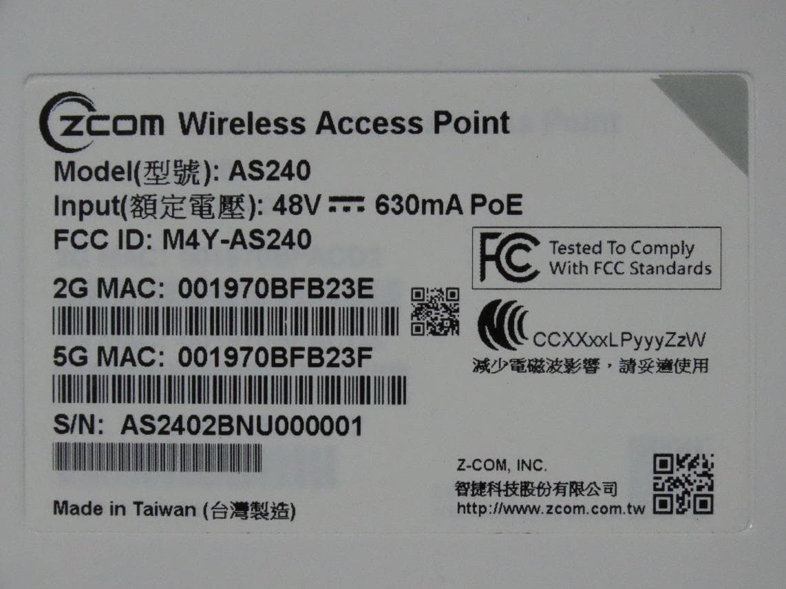
M4Y-AS240
Dec 13, 2022802.11ax Access Point
Equipment Class
DTS - Digital Transmission System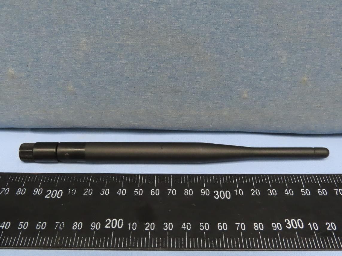
M4Y-AC720M
Aug 14, 2022802.11ac Wireless LAN USB Module
Equipment Class
NII - Unlicensed National Information Infrastructure TX
M4Y-SP230
Feb 21, 2021802.11 ac Wave 2 Access Point
Equipment Class
NII - Unlicensed National Information Infrastructure TX
M4Y-SP220C02
Jan 21, 2020802.11ac Access Point
Equipment Class
NII - Unlicensed National Information Infrastructure TX
M4Y-SP220C03
Jan 20, 20205GHz 11ac Wireless Bridge
Equipment Class
NII - Unlicensed National Information Infrastructure TX