M4Y-0XG350802.11g Cardbus Wireless LAN Card
Z Com Inc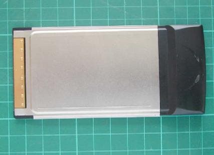
Click to zoom
Application Details
- Equipment Class
- DTS - Digital Transmission System
- Date of Grant
- Dec 07, 2003
- Application Purpose
- Original Equipment
- Date of Application
- Dec 07, 2003
- Equipment Note
- 802.11g Cardbus Wireless LAN Card
- Frequency Range
- 2412.00000000 - 2462.00000000
- Company
- Z Com Inc
- Country
- Taiwan
Documents & Files
Document Text
Text extracted from the exhibit documents filed with the FCC. Open a document above to read the original.
Users Manual
- 1 - IEEE802.11g Cardbus Wireless LAN Card Date of Issue: APR. 25th, 2003 - 2 - Table of Contents Chapter 1 About IEEE802.11g Cardbus Wireless LAN Card.............3 1-1 Features and Benefits...................................................................................................3 1-2 Applications.................................................................................................................3 1-3 Product Kit...................................................................................................................5 1-4 About IEEE802.11g Cardbus Wireless LAN Card LED Indicators...............................5 Chapter 2 Getting Started.....................................................................6 2-1 Before Installation........................................................................................................6 2-2 Insert the IEEE802.11g Cardbus Wireless LAN Card...................................................6 Chapter 3 Install Driver for Windows.................................................7 3-1 Set up IEEE802.11g Cardbus Wireless LAN Card for Windows XP.............................7 3-2 Set up IEEE802.11g Cardbus Wireless LAN Card for Windows 2000........................13 3-3 Set up IEEE802.11g Cardbus Wireless LAN Card for Windows 98SE/ ME................17 Chapter 4 Configure the IEEE802.11g Cardbus Wireless LAN Card ................................................................................................................21 4-1 Install the WLAN Utility............................................................................................21 4-2 Use the WLAN Utility...............................................................................................23 Basic Setting............................................................................................................23 Advance Setting.......................................................................................................30 Limited Warranty.................................................................................33 - 3 - Chapter 1 About IEEE802.11g Cardbus Wireless LAN Card The IEEE802.11g Cardbus Wireless LAN Card is an enhanced high-performance, that supports high-speed wireless networking at home, or at office. IEEE802.11g Cardbus Wireless LAN Card is able to communicate with any 802.11b and 802.11g compliant products. 1-1 Features and Benefits 1. Supports 1, 2, 5.5, 11 Mbps and up to 54Mbps data rate. 2. Working range up to 800 ft. in an open environment. 3. Seamless connectivity to wired Ethernet and PC network LAN’s augments existing networks quickly and easily. 4. Greater flexibility to locate or move networked PCs. 5. Wireless connection without the cost of cabling. 6. Easy to install and user friendly, just Plug and Play. 7. Low power consumption. 8. Supports a variety of operating systems (Win98SE/ME/2000/XP) 9. 64-bit and 128-bits WEP encryption capable. 10. Provides Window-based Diagnostic Tools, most notably, Site Survey, Link Quality Test and Access Point Browser. 1-2 Applications IEEE802.11g Cardbus Wireless LAN Card offers a fast, reliable, cost-effective solution for wireless client access to the network in applications like these: 1. Remote access to corporate network information E-mail, file transfer and terminal emulation. 2. Difficult-to-wire environments Historical or old buildings, asbestos installations, and open area where wiring is difficult to deploy. - 4 - 3. Frequently changing environments Retailers, manufacturers and those who frequently rearrange the workplace and change location. 4. Temporary LANs for special projects or peak time - Trade shows, exhibitions and construction sites where a temporary network will be practical. - Retailers, airline and shipping companies need additional workstations during peak period. - Auditors requiring workgroups at customer sites. 5. Access to database for mobile workers Doctors, nurses, retailers, accessing their database while being mobile in the hospital, retail store or office campus. 6. SOHO (Small Office and Home Office) users SOHO users need easy and quick installation of a small computer network. 7. High security connection The secure wireless network can be installed quickly and provide flexibility. - 5 - 1-3 Product Kit IEEE802.11g Cardbus Wireless LAN Card comes with the following items. Please go through each item below. If any of listed items appears to be damaged or missing, please contact your local dealer. IEEE802.11g Cardbus Wireless LAN Card l IEEE802.11g Cardbus Wireless LAN Card................................................... x 1 l 802.11g PC Card Software and Documentation CD ............................. x 1 l IEEE802.11g Cardbus Wireless LAN Card Quick Installation Guide.................... x 1 1-4 About IEEE802.11g Cardbus Wireless LAN Card LED Indicators The 802.11g Wireless LAN PC Card has two LED indicators. The behavior of the indicators is described as below: Power LED n OFF – No light n ON – Solid Yellow Link LED n Solid Green – Connect with the Access Point or Ad-Hoc wireless workstation. n Blinking Orange – Indicate the device is active data through the Access Point or Ad-Hoc wireless workstation. PWR LINK - 6 - Chapter 2 Getting Started This chapter describes the instructions that guide you through the proper installation of your IEEE802.11g Cardbus Wireless LAN Card for the Windows XP/2000/ME/98SE operating systems. The complete installation of the IEEE802.11g Cardbus Wireless LAN Card consists of the following steps: STEP 1: Insert your IEEE802.11g Cardbus Wireless LAN Card into your notebook. STEP 2: Install the corresponding driver and utility. STEP 3: Set basic settings. STEP 4: Finish Installation. 2-1 Before Installation In addition to the items shipped with the client adapter, you will also need the following in order to install the adapter: 1. A computer equipped with a PCI slot. 2. Windows XP/2000/98SE/ME (with a Windo…
Text truncated - open the document above for the full version.
Cover Letter(s)
American Telecommunications Certification Body Inc. 6731 Whittier Ave, McLean, VA 22101 November 25, 2003 RE: Z-COM Inc. FCC ID: M4Y-OXG350 I have a few comments on the above referenced Application. General Items 1) The phrases "FOR HOME OR OFFICE USE" and "Tested to Comply with FCC Standards" are not required to be on the label due to the devices size. However, this information should be in the users manual (15.19(b)(3). Please correct the users manual to include this. 1) EMC Report 2) Please explain why certain radiated spurious emissions > 1 GHz in the tables are significantly below the ground floor levels specified below the tables. 3) SAR Report 3) Please comment on if the scan procedures given on page 15 for the SAR system validation also apply to the general scan procedures for the test scans. 4) The maximum conducted output of this device was measured as 19.73 dBm and the EUT also contains a +2 dBi gain antenna (conducted = 94 mW, EIRP = 149 mW). The FCC has stipulated that PCMCIA cards with conducted or EIRP output power in excess of 100 mW must be tested in 3 typical units for each approved hosts. Please refer to attachment. 5) The final test plots do not appear to show the actual measured SAR values. Please explain. 6) The test report should contain the composition, ingredients, and amounts for tissue liquid listed. 7) Please comment on if the first 2 measurements points in a direction perpendicular to the surface of the phantom during the zoom scan and closest to the phantom surface, were within 1 cm of the surface. Timothy R. Johnson Examining Engineer mailto: [email protected] The items indicated above must be submitted before processing can continue on the above referenced application. Failure to provide the requested information may result in application termination. Correspondence should be considered part of the permanent submission and may be viewed from the Internet after a Grant of Equipment Authorization is issued. Please do not respond to this correspondence using the email reply button. In order for your response to be processed expeditiously, you must submit your documents through the AmericanTCB.com website. Also, please note that partial responses increase processing time and should not be submitted. Any questions about the content of this correspondence should be directed to the sender.
Cover Letter(s)
Dear Timothy, How are you? I just uploaded the supplementary to ATCB website as per your review comments. For the detail explanation, please see below: 1. Modified the user manual as per your comments. 2. Sorry for typing error for the noise floor, we modified the FCC report for radiated spurious emission data. 3. Yes, the test scan procedure for system validation also apply to the general scan procedure except for the set-up position. For general scan, the EUT was placed at the side of phantom. For validation scan, the dipole antenna was placed at the bottom of phantom. 4. 5. 6 We have measured the 3 host for SAR Testing, and recorded in report. 7. The distance is 3.5mm, please find the section 2.3 of SAR report for reference. I hope the supplementary will satisfy all the requirement for reviewing this application. If you have further question, please feel free to contact me. Best Regards, Julia Chu/ Intertek Taiwan -----Original Message----- From: Timothy R. Johnson [mailto:[email protected] ] Sent: Wednesday, November 26, 2003 12:04 PM To: [email protected]; [email protected] Cc: [email protected]; [email protected] Subject: Review of Z-COM, Inc., FCC ID: M4Y-0XG350 Elton, Attached are comments regarding review of this application. Thank You, To: [email protected] Subject: RE: Review of Z-COM, Inc., FCC ID: M4Y-0XG350 Page 1 of 2In 12/8/2003Printed for "Timothy R. Johnson" <[email protected]> Timothy R. Johnson, NARTE Certified EMC Engineer (No. EMC-002205-NE) Examining Engineer American TCB, Inc. 6731 Whittier Ave. McLean, VA 22101 email: [email protected] alternate email: [email protected] direct number: 404-414-8071 corporate phone: 703-847-4700 corporate fax: 703-847-6888 Your Global Partners in Quality ________________________________________________________________ Confidentiality Notice: All information or opinions expressed in this message and/or any attachments are those of the author and are not necessarily those of Intertek Testing Services or its associated companies. Intertek Testing Services accepts no responsibility for loss or damage arising from its use, including damage from virus. Any personal data contained in this e-mail is treated with the strictest confidence. If you have received this message in error, please notify us immediately and delete it from your system. Our privacy policy can be found at http://www.intertek -labtest.com/home/privacy.htm Please note that any direct business correspondence contained in this e-mail is subject to our business Terms & Conditions available upon request from the sender. Page 2 of 2In 12/8/2003Printed for "Timothy R. Johnson" <[email protected]>
Cover Letter(s)
Zcom, Inc. 7F-2, No.9, Prosperity 1St RD., Science-Based Industrial Park, Hsinchu, Taiwan R.O.C. TEL: (886)-3-3577364 ext.147 FAX: (886)-3-5639241 "I, an officer of Z-Com, Inc. do hereby authorize Intertek Testing Services to act on our behalf in front of the Federal Communications Commission with respect to all matters relating to certification of equipment under Part 15 and Part 18 of the FCC Rules until further notice." I further certify that no party (as defined in §1.2002(b) of CFR 47, 1992) to this application, including myself, is subject to a denial of federal benefits, that includes FCC benefits, pursuant to Section 5301 of the Anti-Drug Abuse Act of 1988, 21 U.S.C.,853(a). By Beryl Lin Title Product Manager Signature Printed
External Photos
Photo 1: Exterior photo XG-350 XG-350
ID Label/Location Info
FCC ID Label Location
Internal Photos
Photo 1: Interior photo XG-350 Photo 2: Interior photo XG-350 Photo 3: Interior photo XG-350
RF Exposure Info
0597 ILAC MRA Specific Absorption Rate (SAR) Test Report for Z-Com, Inc. on the 56Mbps WLAN Card Bus Model Number: XG-350 Test Report: EME-031164 Date of Report: Oct. 31, 2003 Date of test: Oct. 24, 2003 Total No of Pages Contained in this Report: 90 Accredited for testing to FCC Part 15 Tested by: Kevin Chen Reviewed by: Elton Chen Review Date: Dec. 5, 2003 All services undertaken are subject to the following general policy: Reports are submitted for exclusive use of the client to whom they are addressed. Their significance is subject to the adequacy and representative character of the samples and to the comprehensiveness of the tests, examinations or surveys made. This report shall not be reproduced except in full, without written consent of Intertek Testing Services, Taiwan Ltd. FCC ID. : M4Y-0XG350 Report No.: EME-031164 Page 2 of 90 Table of Contents 1.0 Job Description...........................................................................................................4 1.1 Client Information...................................................................................................4 1.2 Equipment under test (EUT)...................................................................................4 Portable.............................................................................................................................4 1.3 Test plan reference..................................................................................................5 1.4 System test configuration........................................................................................5 1.4.1 System block diagram & Support equipment......................................................5 1.4.2 Test Position.........................................................................................................6 1.4.3 Test Condition......................................................................................................6 1.5 Modifications required for compliance...................................................................7 1.6 Additions, deviations and exclusions from standards.............................................7 2.0 SAR Evaluation..........................................................................................................8 2.1 SAR Limits.............................................................................................................8 2.2 Configuration Photographs.....................................................................................9 2.3 SAR measurement system....................................................................................19 2.4 SAR measurement system validation...................................................................20 2.4.1 System Validation result.....................................................................................21 2.4.2 System Performance Check result.....................................................................23 2.5 Test Result.............................................................................................................26 3.0 Test Equipment.........................................................................................................29 3.1 Equipment List......................................................................................................29 3.2 Body Tissue Simulating Liquid for evaluation test...............................................30 3.3 Head Tissue Simulating Liquid for System performance Check test...................31 3.4 E-Field Probe and 2450MHz Balanced dipole antenna Calibration.....................31 4.0 Measurement Uncertainty.........................................................................................32 5.0 Measurement Traceability.........................................................................................35 6.0 WARNING LABEL INFORMATION - USA..........................................................36 7.0 REFERENCES.........................................................................................................37 8.0 DOCUMENT HISTORY..........................................................................................38 APPENDIX A - SAR Evaluation Data...........................................................................39 APPENDIX B – 2450MHz body liquid Calibration Data..............................................58 APPENDIX C - E-Field Probe and 2450MHz Balanced Dipole Antenna Certificate and Calibration Data..............................................................................................................64 FCC ID. : M4Y-0XG350 Report No.: EME-031164 Page 3 of 90 STATEMENT OF COMPLIANCE The Z-Com sample device, model # XG-350 was evaluated in accordance with the requirements for compliance testing defined in FCC OET Bulletin 65, Supplement C (Edition 01-01). Testing was performed at the Intertek Testing Services facility in Hsinchu, Taiwan. For the evaluation, the dosimetric assessment system INDEXSAR SARA2 was used. The phantom employed was the box phantom of 2mm thick in one wall. The total uncertainty for the evaluation of the spatial peak SAR values averaged over a cube of 1g tissue mass had been assessed for this system to be ±29.7%. The device was tested at their maximum output power declared by the Z-Com. In summary, the maximum spatial peak SAR value for the sample device averaged over 1g was found to be: Phantom Position SAR 1g , mW/g 2mm thick box phantom wall EUT perpendicular to the phantom, 0 mm separation. 0.704 mW/g. In conclusion, the tested Sample device was found to be in compliance with the requirements defined in OET Bulletin 65, Supplement C (Edition 01-01) for body configurations. FCC ID. : M4Y-0XG350 Report No.: EME-031164 Page 4 of 90 1.0 Job Description 1.1 Client Information The XG-350 has been tested at the request of: Company: Z-COM, Inc. 7F-2, No. 9, Prosperity 1 st RD., Science-Based Industrial Park, Hsinchu, Taiwan 1.2…
Text truncated - open the document above for the full version.
Test Report
FCC ID. : M4Y-0XG350 Report No.: EME-031162 Page 1 of 52 EMC TEST REPORT Report No. : EME-031162 Model No. : XG-350 Issued Date : Nov. 3, 2003 Applicant : Z-COM, Inc. 7F-2, No. 9, Prosperity 1 st RD., Science-Based Industrial Park, Hsinchu, Taiwan Test By : Intertek Testing Services Taiwan Ltd. No. 11, Lane 275, Ko-Nan 1 Street, Chia-Tung Li, Shiang-Shan District, Hsinchu City, Taiwan This test report consists of 52 pages in total. It may be duplicated completely for legal use with the allowance of the applicant. It shall not be reproduced except in full, without the written approval of Intertek Laboratory. The test result in this report only applies to the tested sample. Jackey Chiu Project Engineer Reviewed By Elton Chen FCC ID. : M4Y-0XG350 Report No.: EME-031162 Page 2 of 52 Table of Contents Summary of Tests..........................................................................................................3 1. General information..................................................................................................4 1.1 Identification of the EUT.....................................................................................4 1.2 Additional information about the EUT.................................................................4 1.3 Antenna description.............................................................................................5 1.4 Peripherals equipment.........................................................................................5 2. Test specifications.....................................................................................................6 2.1 Test standard........................................................................................................6 2.2 Operation mode...................................................................................................6 2.3 Test equipment....................................................................................................7 3. Minimum 6dB Bandwidth test...................................................................................8 3.1 Operating environment........................................................................................8 3.2 Test setup & procedure........................................................................................8 3.3 Measured data of Minimum 6dB Bandwidth test results......................................8 4. Maximum Output Power test...................................................................................15 4.1 Operating environment......................................................................................15 4.2 Test setup & procedure......................................................................................15 4.3 Measured data of Maximum Output Power test results.......................................16 5. Radiated Emission test............................................................................................17 5.1 Operating environment......................................................................................17 5.2 Test setup & procedure......................................................................................17 5.3 Emission limits..................................................................................................18 5.4 Radiated spurious emission test data..................................................................19 5.4.1 Measurement results: frequencies equal to or less than 1 GHz.........................19 5.4.2 Measurement results: frequency above 1GHz.................................................21 6. Power Spectrum Density test...................................................................................25 6.1 Operating environment......................................................................................25 6.2 Test setup & procedure......................................................................................25 6.3 Measured data of Power Spectrum Density test results.......................................25 7. Emission on the band edge §FCC 15.247(C)...........................................................32 7.1 Band-edge (Conducted method).........................................................................33 7.2 Band-edge (Radiated method)............................................................................37 8. Power Line Conducted Emission test §FCC 15.207.................................................45 8.1 Operating environment......................................................................................45 8.2 Test setup & procedure......................................................................................45 8.3 Power Line Conducted Emission test data..........................................................47 FCC ID. : M4Y-0XG350 Report No.: EME-031162 Page 3 of 52 Summary of Tests 56Mbps WLAN Card Bus-Model: XG-350 FCC ID: M4Y-0XG350 Test Reference Results Minimum 6dB Bandwidth test 15.247(a)(2) Complies Maximum Output Power test 15.247(b) Complies Radiated Spurious Emission test 15.205, 15.209 Complies Power Spectrum Density test 15.247(d) Complies Power Line Conducted Emission test 15.207 Complies FCC ID. : M4Y-0XG350 Report No.: EME-031162 Page 4 of 52 1. General information 1.1 Identification of the EUT Applicant : Z-COM, Inc. Product : 56Mbps WLAN Card Bus Model No. : XG-350 FCC ID. : M4Y-0XG350 Frequency Range : 2412~2462 MHz Channel Number : 11 Channels Frequency of Each Channel : 2412MHz, 2417MHz, 2422MHz, 2427MHz, 2432MHz, 2437MHz, 2442MHz, 2447MHz, 2452MHz, 2457MHz, 2462MHz Type of Modulation : DSSS, OFDM Rated Power : 3.3Vdc Power Cord : N/A Sample Received : Oct. 15, 2003 Test Date(s) : Oct. 16, 2003 to Oct. 24, 2003 A FCC DoC report has been generated for the client. 1.2 Additional information about the EUT The IEEE802.11g Cardbus Wireless LAN Card is an enhanced high-performance, that supports high-speed wireless networking …
Text truncated - open the document above for the full version.
Test Setup Photos
Photo 1: Conducted Emission Test Set-up (front) Photo 2: Conducted Emission Test Set-up (rear)
Test Setup Photos
Photo 1: Radiated Spurious Test Set-up (front) Appendix B4: Radiated Spurious Test Set-up (rear)
Contact Information
Applicant
Jeff jiang(R&D DIV Director)
Technical Contact
Intertek Testing Services Taiwan Ltd.Elton Chen
[email protected](+886)-3-519-1411
No. 11, Ko-Tze-Nan Chia-Tung Li · Hsinchu · Taiwan
Non-Technical Contact
Intertek Testing Services Taiwan Ltd.Elton Chen
[email protected](+886)-3-519-1411
Test Firm
Intertek Testing Services Taiwan Ltd.Alpha Liu
Technical Specifications
| # | Rule Parts | Frequency Range | Power Output |
|---|---|---|---|
| 1 | 15C | 2.41 GHz - 2.46 GHz | 94.00 mW |
Other Applications from Z Com Inc
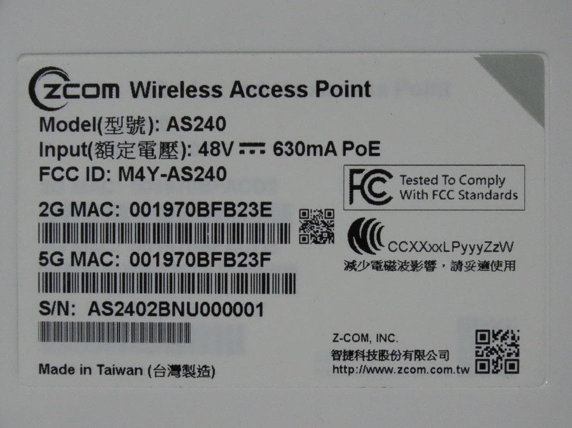
M4Y-AS240
Dec 13, 2022802.11ax Access Point
Equipment Class
DTS - Digital Transmission System
M4Y-AC720M
Aug 14, 2022802.11ac Wireless LAN USB Module
Equipment Class
NII - Unlicensed National Information Infrastructure TX
M4Y-SP230
Feb 21, 2021802.11 ac Wave 2 Access Point
Equipment Class
NII - Unlicensed National Information Infrastructure TX
M4Y-SP220C02
Jan 21, 2020802.11ac Access Point
Equipment Class
NII - Unlicensed National Information Infrastructure TX
M4Y-SP220C03
Jan 20, 20205GHz 11ac Wireless Bridge
Equipment Class
NII - Unlicensed National Information Infrastructure TX