M4Y-0XG950IEEE 802.11g Wireless LAN PCI Card
Z Com Inc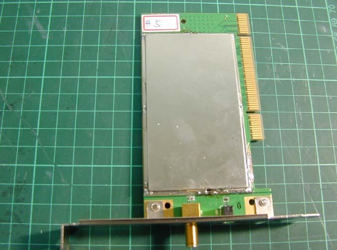
Click to zoom
Application Details
- Equipment Class
- DTS - Digital Transmission System
- Date of Grant
- Aug 17, 2003
- Application Purpose
- Original Equipment
- Date of Application
- Aug 17, 2003
- Equipment Note
- IEEE 802.11g Wireless LAN PCI Card
- Frequency Range
- 2412.00000000 - 2462.00000000
- Company
- Z Com Inc
- Country
- Taiwan
Documents & Files
Document Text
Text extracted from the exhibit documents filed with the FCC. Open a document above to read the original.
Users Manual
- 1 - IEEE 802.11g Wireless LAN PCI Card Date of Issue: Aug. 15th, 2003 - 2 - Table of Contents Chapter 1 About Wireless LAN PCI Card............................. 3 1-1 Features and Benefits ......................................................................................................3 1-2 Applications ..................................................................................................................... 4 1-3 Product Kit....................................................................................................................... 5 1-4 About Wireless LAN PCI Card LED Indicators .............................................................. 5 Chapter 2 Getting Started ....................................................... 6 2-1 Before Installation ........................................................................................................... 6 2-2 Insert the 802.11g Wireless LAN PCI Card ..................................................................... 6 Chapter 3 Install Driver for Windows.................................... 7 3-1 Set up Wireless LAN PCI Card for Windows XP ............................................................. 7 3-2 Set up Wireless LAN PCI Card for Windows 2000 ........................................................ 13 3-3 Set up Wireless LAN PCI Card for Windows 98SE/ ME................................................ 17 Chapter 4 Configure the Wireless LAN PCI Card ....................... 21 4-1 Install the WLAN Utility ................................................................................................ 21 4-2 Use the WLAN Utility .................................................................................................... 23 Basic Setting ................................................................................................................ 23 Advance Setting............................................................................................................ 31 Limited Warranty .................................................................. 33 - 3 - Chapter 1 About Wireless LAN PCI Card The 802.11g Wireless LAN PCI Card is a standard PCI adapter that fits into any standard PCI slot in a desktop computer. The 802.11g Wireless LAN PCI Card is an enhanced high-performance, that supports high-speed wireless networking at home, at office or in public places. 802.11g Wireless LAN PCI Card is able to communicate with any 802.11b and 802.11g compliant products. 1-1 Features and Benefits 1. Supports 1, 2, 5.5, 11 Mbps and up to 54Mbps data rate. 2. Working range up to 800 ft. in an open environment. 3. Seamless connectivity to wired Ethernet and PC network LAN’s augments existing networks quickly and easily. 4. Greater flexibility to locate or move networked PCs. 5. Wireless connection without the cost of cabling. 6. Easy to install and user friendly, just Plug and Play. 7. Low power consumption. 8. Supports a variety of operating systems (Win98SE/ME/2000/XP) 9. 64-bit and 128-bits WEP encryption capable. 10. Provides Window-based Diagnostic Tools, most notably, Site Survey, Link Quality Test and Access Point Browser. 11. Compliant with protocol 802.11g v.8.2. 12. Protection mechanism, which can avoid 11g packet and 11b packet colliding with each other. 13. Supports Nitro mode (packet bursting), which can highly increase 11g efficiency. - 4 - 1-2 Applications 802.11g Wireless LAN PCI Card offers a fast, reliable, cost-effective solution for wireless client access to the network in applications like these: 1. Remote access to corporate network information E-mail, file transfer and terminal emulation. 2. Difficult-to-wire environments Historical or old buildings, asbestos installations, and open area where wiring is difficult to deploy. 3. Frequently changing environments Retailers, manufacturers and those who frequently rearrange the workplace and change location. 4. Temporary LANs for special projects or peak time - Trade shows, exhibitions and construction sites where a temporary network will be practical. - Retailers, airline and shipping companies need additional workstations during peak period. - Auditors requiring workgroups at customer sites. 5. Access to database for mobile workers Doctors, nurses, retailers, accessing their database while being mobile in the hospital, retail store or office campus. 6. SOHO (Small Office and Home Office) users SOHO users need easy and quick installation of a small computer network. 7. High security connection The secure wireless network can be installed quickly and provide flexibility. - 5 - 1-3 Product Kit 802.11g Wireless LAN PCI Card comes with the following items. Please go through each item below. If any of listed items appears to be damaged or missing, please contact your local dealer. 802.11g Wireless LAN PCI Card ! 802.11g Wireless LAN PCI Card..................................................... x 1 ! 802.11g PCI Card Software and Documentation CD ............................. x 1 ! 802.11g Wireless LAN PCI Card Quick Installation Guide...................... x 1 1-4 About Wireless LAN PCI Card LED Indicators The 802.11g Wireless LAN PCI Card has one LED indicator. The behavior of the indicators is described as below: Link LED # Solid Green – Connect with the Access Point or Ad-Hoc wireless workstation. # Blinking Orange – Indicate the device is active data through the Access Point or Ad-Hoc wireless workstation. Link - 6 - Chapter 2 Getting Started This chapter describes the instructions that guide you through the proper installation of your 802.11g Wireless LAN PCI Card for the Windows XP/2000/ME/98SE operating systems. The complete installation of the 802.11g Wireless LAN PCI Card consists of the following steps: STEP 1: Insert your Wireless LAN PCI Card into the connector of any free PCI Bus Master expansion slot on your desktop computer. STEP 2: Install the corresponding driver and utility. STEP 3: Set basic settings. STEP 4: Fini…
Text truncated - open the document above for the full version.
Cover Letter(s)
American Telecommunications Certification Body Inc. 6731 Whittier Ave, McLean, VA 22101 August 18, 2003 RE: Z- COM INC. FCC ID: M4Y-0XG950 I have a few comments on this Application. 1.) In the Users Manual under caution on page 34 before the co-location of antennas statement it should read: This equipment complies with FCC radiation exposure limits set forth for an uncontrolled environment. This equipment should be installed and operated with minimum distance 20cm between the radiator & your body. Please revise and upload files to ATCB. Thank you, Douglas E. Noble Examining Engineer mailto: [email protected] The items indicated above must be submitted before processing can continue on the above referenced application. Failure to provide the requested information may result in application termination. Correspondence should be considered part of the permanent submission and may be viewed from the Internet after a Grant of Equipment Authorization is issued. Please do not respond to this correspondence using the email reply button. In order for your response to be processed expeditiously, you must submit your documents through the AmericanTCB.com website. Also, please note that partial responses increase processing time and should not be submitted. Any questions about the content of this correspondence should be directed to the sender.
External Photos
Photo 1: Exterior photo XG-950 Photo 2: Photo of Antenna XG-950
ID Label/Location Info
FCC ID Label Location
Internal Photos
Photo 1: Interior photo XG-950 Photo 2: Interior photo XG-950 Photo 3: Interior photo XG-950 Photo 4: Interior photo XG-950
RF Exposure Info
Intertek Testing Services ETL SEMKO FCC ID. : M4Y-0XG950 Report No.: EME-030876 Page 1 of 6 Maximum Permissible Exposure (MPE) Evaluation Report Report No. : EME-030876 Model No. : XG-950 Issued Date : Aug. 7, 2003 Applicant : Z-COM, Inc. 7F-2, No. 9, Prosperity 1 st RD., Science-Based Industrial Park, Hsinchu, Taiwan Test By : Intertek Testing Services Taiwan Ltd. No. 11, Lane 275, Ko-Nan 1 Street, Chia-Tung Li, Shiang-Shan District, Hsinchu City, Taiwan This test report consists of 6 pages in total. It may be duplicated completely for legal use with the allowance of the applicant. It shall not be reproduced except in full, without the written approval of ITS Laboratory. The test result in this report only applies to the tested sample. Jerry Liu Project Engineer Reviewed By Elton Chen Intertek Testing Services ETL SEMKO FCC ID. : M4Y-0XG950 Report No.: EME-030876 Page 2 of 6 Table of Contents Summary of Tests.........................................................................................................3 1. Introduction..............................................................................................................4 2. RF Exposure Limit...................................................................................................4 3. RF Exposure calculations..........................................................................................5 4. Test results................................................................................................................5 Intertek Testing Services ETL SEMKO FCC ID. : M4Y-0XG950 Report No.: EME-030876 Page 3 of 6 Summary of Tests MPE Evaluation meet FCC OET No. 65: 1997/ IEEE C95.1-1999 IEEE 802.11g Wireless LAN PCI Card-Model: XG-950 FCC ID: M4Y-0XG950 Test Reference Results MPE Evaluation FCC Guidelines for Human Exposure IEEE C95.1 Complies Intertek Testing Services ETL SEMKO FCC ID. : M4Y-0XG950 Report No.: EME-030876 Page 4 of 6 1. Introduction The EUT operates in the 2.4GHz ISM band. Due to the EUT (include antenna) at its normal operation distance is at least 20 cm from the human body, the EUT was defined as a Mobile Device. The reason to do the MPE Evaluation is to avoid the RF hazard to human body. The maximum output power and gain of the antenna were used to calculate the limited Power density (S) at 20cm distance away from the product. The limit for Maximum Permissible Exposure (MPE) specified in FCC 1.1310 is followed. 2. RF Exposure Limit According to FCC 1.1310: The criteria listed in the following table shall be used to evaluate the environmental impact of human exposure to radio-frequency (RF) radiation as specified in 1.1307(b). Limits for Maximum Permissible Exposure (MPE) Frequency Range (MHz) Electric Field Strength (V/m) Magnetic Field Strength (A/m) Power Density (mW/cm 2 ) Average Time (minutes) (A) Limits for Occupational / Control Exposures 30-300 61.4 0.163 1.0 6 300-1500 - - F/300 6 1500-100,000 - - 5 6 (B) Limits for General Population / Uncontrolled Exposure 30-300 27.5 0.073 0.2 30 300-1500 - - F/1500 30 1500-100,000 - - 1.0 30 F= Frequency in MHz Intertek Testing Services ETL SEMKO FCC ID. : M4Y-0XG950 Report No.: EME-030876 Page 5 of 6 3. RF Exposure calculations From § FCC 1.1310 table 1, the maximum permissible RF exposure for an uncontrolled environment is 1mW/(cm 2 ) Power density (S) is calculated by the following formula: S = (P * G)/4πR 2 where, S = Power density (mW/cm 2 ) P = Output power to antenna (mW) R = Distance between radiating structure and observation point (cm) G = Gain of antenna in numeric π = 3.1416 Example: Assume a mobile device operates at 2412MHz and its maximum output power is 50mW, and the maximum gain of antenna is 1 (numeric) /0dBi. then the power density (S) = (50 * 1)/4* π *20 2 = 0.00995 (mW/cm 2 ) 4. Test results Test Condition: 802.11b operation (DSSS Modulation) Channel Channel Frequency (MHz) Maximum antenna gain (numeric) Output power to antenna (mW) Power density (mW/cm 2 ) Limit of power density (mW/cm 2 ) 1 2412 1.58 71.45 0.022528 1.0 6 2437 1.58 60.95 0.019219 1.0 11 2462 1.58 49.32 0.015550 1.0 The Notice in Installation Manual has been stated as below: While installing and operating this transmitter, the radio frequency exposure limit of 1mW/(cm*cm) may be exceeded at distances close to the transmitter. therefore, the user must maintain a minimum distance of 20 cm from the device at all time. Intertek Testing Services ETL SEMKO FCC ID. : M4Y-0XG950 Report No.: EME-030876 Page 6 of 6 Test Condition: 802.11g operation (OFDM Modulation) Channel Channel Frequency (MHz) Maximum antenna gain (numeric) Output power to antenna (mW) Power density (mW/cm 2 ) Limit of power density (mW/cm 2 ) 1 2412 1.58 47.64 0.015022 1.0 6 2437 1.58 39.81 0.012552 1.0 11 2462 1.58 33.34 0.010513 1.0 The Notice in Installation Manual has been stated as below: While installing and operating this transmitter, the radio frequency exposure limit of 1mW/(cm*cm) may be exceeded at distances close to the transmitter. therefore, the user must maintain a minimum distance of 20 cm from the device at all time.
Test Report
Intertek Testing Services ETL SEMKO FCC ID. : M4Y-0XG950 Report No.: EME-030876 Page 1 of 53 EMC TEST REPORT Report No. : EME-030876 Model No. : XG-950 Issued Date : Aug. 7, 2003 Applicant : Z-COM, Inc. 7F-2, No. 9, Prosperity 1 st RD., Science-Based Industrial Park, Hsinchu, Taiwan Test By : Intertek Testing Services Taiwan Ltd. No. 11, Lane 275, Ko-Nan 1 Street, Chia-Tung Li, Shiang-Shan District, Hsinchu City, Taiwan This test report consists of 53 pages in total. It may be duplicated completely for legal use with the allowance of the applicant. It shall not be reproduced except in full, without the written approval of ITS Laboratory. The test result in this report only applies to the tested sample. Jerry Liu Project Engineer Reviewed By Elton Chen Intertek Testing Services ETL SEMKO FCC ID. : M4Y-0XG950 Report No.: EME-030876 Page 2 of 53 Table of Contents Summary of Tests.........................................................................................................3 1. General information..................................................................................................4 1.1 Identification of the EUT....................................................................................4 1.2 Additional information about the EUT................................................................4 1.3 Antenna description............................................................................................5 1.4 Peripherals equipment........................................................................................5 2. Test specifications.....................................................................................................6 2.1 Test standard......................................................................................................6 2.2 Operation mode..................................................................................................6 2.3 Test equipment...................................................................................................7 3. Minimum 6dB Bandwidth test..................................................................................8 3.1 Operating environment.......................................................................................8 3.2 Test setup & procedure.......................................................................................8 3.3 Measured data of Minimum 6dB Bandwidth test results.....................................8 4. Maximum Output Power test..................................................................................15 4.1 Operating environment.....................................................................................15 4.2 Test setup & procedure.....................................................................................15 4.3 Measured data of Maximum Output Power test results.....................................15 5. Radiated Emission test............................................................................................17 5.1 Operating environment.....................................................................................17 5.2 Test setup & procedure.....................................................................................17 5.3 Emission limits.................................................................................................18 5.4 Radiated spurious emission test data.................................................................19 5.4.1 Measurement results: frequencies equal to or less than 1 GHz.......................19 5.4.2 Measurement results: frequency above 1GHz................................................21 6. Power Spectrum Density test..................................................................................27 6.1 Operating environment.....................................................................................27 6.2 Test setup & procedure.....................................................................................27 6.3 Measured data of Power Spectrum Density test results.....................................27 7. Emission on the band edge §FCC 15.247(C)...........................................................33 7.1 Band-edge (Conducted method).......................................................................34 7.2 Band-edge (Radiated method)..........................................................................38 8. Power Line Conducted Emission test §FCC 15.207................................................46 8.1 Operating environment.....................................................................................46 8.2 Test setup & procedure.....................................................................................46 8.3 Power Line Conducted Emission test data........................................................48 Intertek Testing Services ETL SEMKO FCC ID. : M4Y-0XG950 Report No.: EME-030876 Page 3 of 53 Summary of Tests IEEE 802.11g Wireless LAN PCI Card-Model: XG-950 FCC ID: M4Y-0XG950 Test Reference Results Minimum 6dB Bandwidth test 15.247(a)(2) Complies Maximum Output Power test 15.247(b) Complies Radiated Spurious Emission test 15.205, 15.209 Complies Power Spectrum Density test 15.247(d) Complies Power Line Conducted Emission test 15.207 Complies Intertek Testing Services ETL SEMKO FCC ID. : M4Y-0XG950 Report No.: EME-030876 Page 4 of 53 1. General information 1.1 Identification of the EUT Applicant : Z-COM, Inc. Product : IEEE 802.11g Wireless LAN PCI Card Model No. : XG-950 FCC ID. : M4Y-0XG950 Frequency Range : 2412~2462 MHz Channel Number : 11 Channels Frequency of Each Channel : 2412MHz, 2417MHz, 2422MHz, 2427MHz, 2432MHz, 2437MHz, 2442MHz, 2447MHz, 2452MHz, 2457MHz, 2462MHz Type of Modulation : DSSS, OFDM Rated Power : 3.3Vdc Power Cord : N/A Sample Received : July 24, 2003 Test Date(s) : July 24, 2003 ~ Aug. 7, 2003 A FCC DoC report has been generated for the client. 1.2 Additional information about the …
Text truncated - open the document above for the full version.
Test Report
Intertek Testing Services ETL SEMKO Report No.: EME-030875 Page 1 of 19 LABORATORY MEASUREMENTS Pursuant To 47 CFR Part 15 Subpart B (August 20, 2002) And FCC Procedure ANSI C63.4 (2001) Applicant : Z-COM, Inc. 7F-2, No. 9, Prosperity 1 st RD., Science-Based Industrial Park, Hsinchu, Taiwan Model No. : XG-950 Issue Date : Aug. 7, 2003 Test Site Location : No. 11, Lane 275, Ko-Nan 1 Street, Chia-Tung Li, Shiang-Shan District, Hsinchu City, Taiwan We attest to the accuracy of this report : This test report consists of 19 pages in total. It may be duplicated completely for legal use with the allowance of the applicant. It shall not be reproduced except in full, without the written approval of ITS Laboratory. The test result in this report only applies to the tested sample. 0597 ILAC MRA Project Engineer Reviewed By Jerry Liu Elton Chen Intertek Testing Services ETL SEMKO Report No.: EME-030875 Page 2 of 19 Table of Contents 1. General Information..................................................................................................3 1.1 General Description of EUT...............................................................................3 1.2 Additional information about the EUT................................................................3 1.3 Description of Peripherals..................................................................................3 2. Test Specifications....................................................................................................4 2.1 Standards............................................................................................................4 2.2 Definition of Device Classification.....................................................................4 2.3 EUT Operation Condition...................................................................................5 3. Test Condition...........................................................................................................6 3.1 Test Equipment...................................................................................................6 3.2 EUT Grounding..................................................................................................6 3.3 Test Environment...............................................................................................6 3.4 Test Platform......................................................................................................6 4. Conducted Emission Measurements (FCC 15.107)...................................................7 4.1 Operating environment.......................................................................................7 4.2 Test Setup and procedure....................................................................................7 4.3 Conducted Emission Limits:...............................................................................8 4.4 Uncertainty of Conducted Emission...................................................................8 4.5 Conducted Emission Data...................................................................................9 5. Radiated Emission Measurements (FCC 15.109).....................................................11 5.1 Operating environment.....................................................................................11 5.2 Test Setup and procedure..................................................................................11 5.3 Radiated Emission Limits:................................................................................12 5.4 Uncertainty of Radiated Emission....................................................................12 5.5 Radiated Emission Test Data............................................................................13 Appendix A1: Exterior photo of EUT.........................................................................14 Appendix A2: Photo of Antenna.................................................................................14 Appendix A3: Interior photo of EUT..........................................................................15 Appendix B1: Conducted Emission Test Set-up (front)...............................................17 Appendix B2: Conducted Emission Test Set-up (rear).................................................17 Appendix B3: Conducted Emission Test Set-up (side)................................................18 Appendix B4: Radiated Emission Test Set-up (front)..................................................19 Appendix B5: Radiated Emission Test Set-up (rear)....................................................19 Intertek Testing Services ETL SEMKO Report No.: EME-030875 Page 3 of 19 1. General Information 1.1 General Description of EUT Product : IEEE 802.11g Wireless LAN PCI Card Model No. : XG-950 Applicant : Z-COM, Inc. FCC ID. : M4Y-0XG950 Rated Power : 3.3Vdc Power Cord : N/A Data Cable : N/A Sample receiving date : July 24, 2003 Testing date : July 24, 2003 ~ Aug. 7, 2003 1.2 Additional information about the EUT The 802.11g Wireless LAN PCI Card is a standard PCI adapter that fits into any standard PCI slot in a desktop computer. The 802.11g Wireless LAN PCI Card is an enhanced high-performance, that supports high-speed wireless networking at home, at office or in public places. 802.11g Wireless LAN PCI Card is able to communicate with any 802.11b and 802.11g compliant products. For more detail features, please refer to user's Manual. 1.3 Description of Peripherals Peripherals Manufacturer Product No. Serial No. PC HP DTPC-16 SG20400787 Key Board HP SK-2502C M011234429 Monitor HP D8897 CN14835153 Mouse HP M-S48a LZE14652508 Printer HP C2642A TH86K1N2ZB Modem Dynalink V1456VQE 00V230A00051494 Intertek Testing Services ETL SEMKO Report No.: EME-030875 Page 4 of 19 2. Test Specifications 2.1 Standards Both conducted and radiated emission tests were performed according to the procedures in ANSI C63.4: 2001. Test results are in compliance with the requirements of 47 CFR…
Text truncated - open the document above for the full version.
Test Setup Photos
Photo 1: Conducted Test Set-up (front) Photo 2: Conducted Test Set-up (rear) XG-950 XG-950 Photo 3: Conducted Test Set-up (side)
Test Setup Photos
Photo 1: Spurious Set-up photo(front) Photo 2: Spurious Set-up photo (rear)
Contact Information
Applicant
Jeff jiang(R&D DIV Director)
Technical Contact
Intertektesting Services Taiwan Ltd.Elton Chen
[email protected]+886-3-519-1411
No. 11, Li-Tze-Nam Chia-Tung Li · Hsinchu · Taiwan
Test Firm
Intertek Testing Services Taiwan Ltd.Alpha Liu
Technical Specifications
| # | Rule Parts | Frequency Range | Power Output |
|---|---|---|---|
| 1 | 15C | 2.41 GHz - 2.46 GHz | 71.00 mW |
Other Applications from Z Com Inc
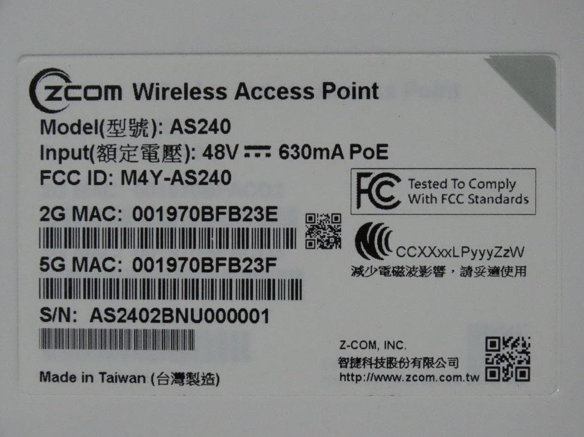
M4Y-AS240
Dec 13, 2022802.11ax Access Point
Equipment Class
DTS - Digital Transmission System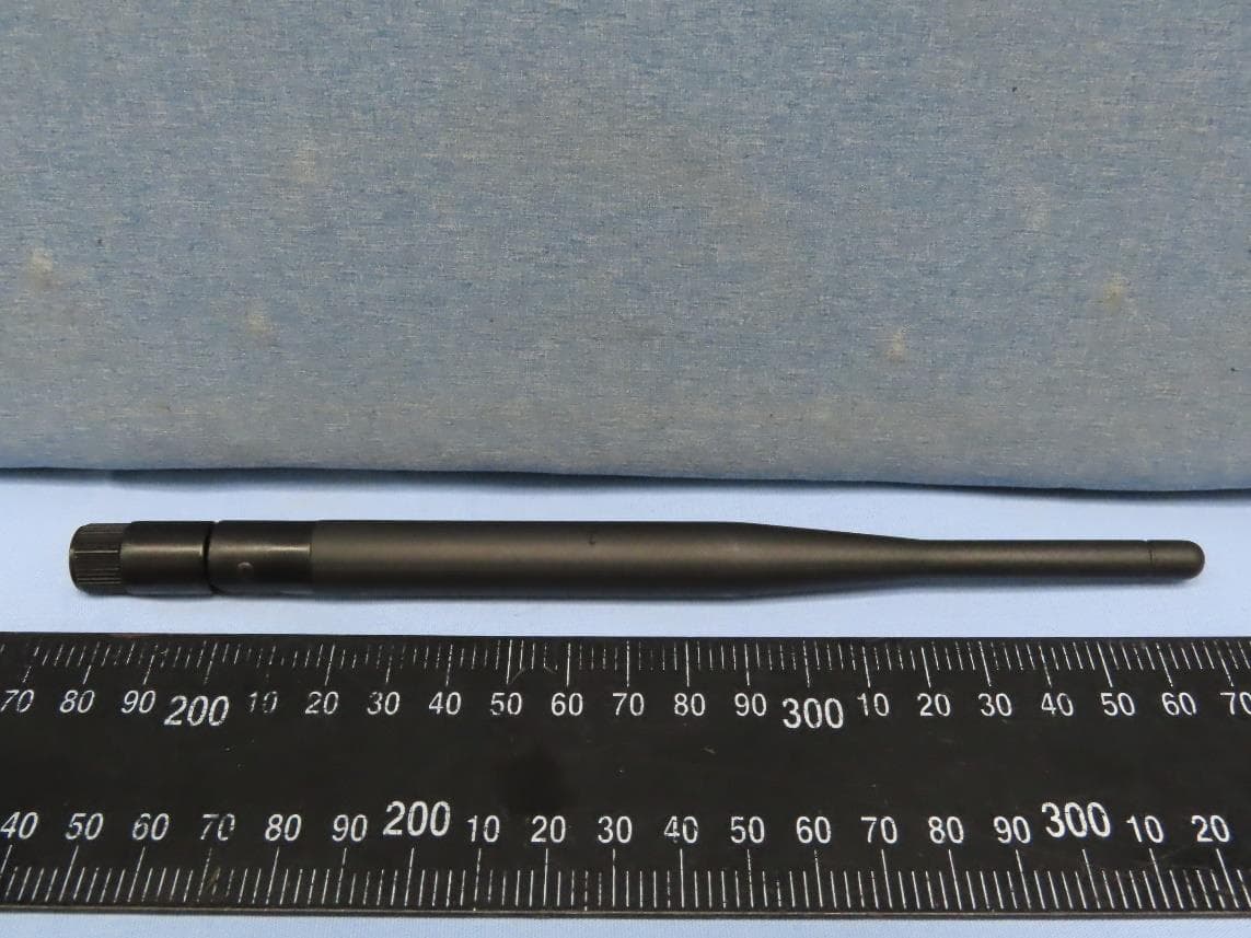
M4Y-AC720M
Aug 14, 2022802.11ac Wireless LAN USB Module
Equipment Class
NII - Unlicensed National Information Infrastructure TX
M4Y-SP230
Feb 21, 2021802.11 ac Wave 2 Access Point
Equipment Class
NII - Unlicensed National Information Infrastructure TX
M4Y-SP220C02
Jan 21, 2020802.11ac Access Point
Equipment Class
NII - Unlicensed National Information Infrastructure TX
M4Y-SP220C03
Jan 20, 20205GHz 11ac Wireless Bridge
Equipment Class
NII - Unlicensed National Information Infrastructure TX