M4Y-GZ901900MHz Wireless miniPCI Module
Z Com Inc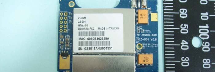
Click to zoom
Application Details
- Equipment Class
- DTS - Digital Transmission System
- Date of Grant
- Jan 16, 2007
- Application Purpose
- Original Equipment
- Date of Application
- Jan 16, 2007
- Equipment Note
- 900MHz Wireless miniPCI Module
- Frequency Range
- 908.00000000 - 923.00000000
- Company
- Z Com Inc
- Country
- Taiwan
Documents & Files
Document Text
Text extracted from the exhibit documents filed with the FCC. Open a document above to read the original.
Users Manual
- 1 - GZ-901 900MHz Wireless Network Mini-PCI Adapter Date of Issue: Dec. 14th, 2006 - 2 - Technical Support The firmware version of the 900 MHz Wireless Network Mini-PCI Adapter is displayed on the utility About window. Users could download the most recent software version from the supplier’s web site or refer to the selling contact for the latest software information. If you have difficulty resolving the problem while installing or using the 900 MHz Wireless Network Mini-PCI Adapter, please contact the supplier for support. About This Manual The 900 MHz Wireless Network Mini-PCI Adapter User Manual is first published on December, 2006. The manual includes procedures for the setup of the 900 MHz Wireless Network Mini-PCI Adapter under Access Point. Take a moment to read through this manual and familiarize yourself with wireless technology. - 3 - FCC Information This device, 900 MHz Wireless Network Mini-PCI Adapter, complies with Part 15 of the FCC Rules. Operation is subject to the following two conditions: (1) this device may not cause harmful interference, and (2) this device must accept any interference received; including interference that may cause undesired operation. Federal Communications Commission (FCC) Statement This Equipment has been tested and found to comply with the limits for a Class B digital device, pursuant to Part 15 of the FCC rules. These limits are designed to provide reasonable protection against harmful interference in a residential installation. This equipment generates, uses and can radiate radio frequency energy and, if not installed and used in accordance with the instructions, may cause harmful interference to radio communications. However, there is no guarantee that interference will not occur in a particular installation. If this equipment does cause harmful interference to radio or television reception, which can be determined by turning the equipment off and on, the user is encouraged to try to correct the interference by one or more of the following measures: - Reorient or relocate the receiving antenna. - Increase the separation between the equipment and receiver. - Connect the equipment into an outlet on a circuit different from that to which the receiver is connected. - Consult the dealer or an experienced radio/TV technician for help. Warning: Any changes or modifications to this unit not expressly approved by the party responsible for compliance could void the user's authority to operate the equipment. Tested to comply with FCC standard. FOR HOME OR OFFICE USE. FCC RF Radiation Exposure Statement: 1. This module is intended for OEM integrator. The OEM integrator is still responsible for the FCC compliance requirement of the end product which integrates this module. 20cm minimum distance has to be able to be maintained between the antenna and the users for the host this module is integrated into. Under such configuration, the FCC radiation exposure limits set forth for an population/uncontrolled environment can be satisfied. 2. This device and its antenna(s) must not be co-located or operating in conjunction with any other antenna or transmitter. - 1 - USERS MANUAL OF THE END PRODUCT: In the users manual of the end product, the end user has to be informed to keep at least 20cm separation with the antenna while this end product is installed and operated. The end user has to be informed that the FCC radio-frequency exposure guidelines for an uncontrolled environment can be satisfied. The end user has to also be informed that any changes or modifications not expressly approved by the manufacturer could void the user's authority to operate this equipment. If the size of the end product is smaller than 8x10cm, then additional FCC part 15.19 statement is required to be available in the users manual: This device complies with Part 15 of FCC rules. Operation is subject to the following two conditions: (1) this device may not cause harmful interference and (2) this device must accept any interference received, including interference that may cause undesired operation. LABEL OF THE END PRODUCT: The final end product must be labeled in a visible area with the following " Contains TX FCC ID: M4Y-GZ901 ". If the size of the end product is larger than 8x10cm, then the following FCC part 15.19 statement has to also be available on the label: This device complies with Part 15 of FCC rules. Operation is subject to the following two conditions: (1) this device may not cause harmful interference and (2) this device must accept any interference received, including interference that may cause undesired operation. - 1 - Table of Contents Chapter 1 About Wireless Network Mini-PCI Adapter...................................... 2 1-1 Features and Benefits.......................................................................................................2 1-2 Applications ..................................................................................................................... 3 1-3 Product Kit....................................................................................................................... 4 Chapter 2 Getting Started...................................................................................... 5 2-1 Before Installation ........................................................................................................... 5 2-2 Insert the 900MHz Wireless Network Mini-PCI Adapter ............................................... 5 Chapter 3 Install Driver for Windows .................................................................. 6 3-1 Set up Wireless Network Mini-PCI Adapter for Windows XP ....................................... 6 3-2 Set up Wireless Network Mini-PCI Adapter for Windows 2000................................... 13 3-3 Set up Wireless Network Mini-PCI Adapter for Windows 98SE/ ME.......................... 18 Chapter 4 Configure the Wireless Network Mini-PCI Adapter ...................... 22 4-1 Install the WLAN …
Text truncated - open the document above for the full version.
Cover Letter(s)
Page No. : 6 Confidential Letter Date: 2006/12/13 Federal Communications Commission Authorization and Evaluation Division FCC IDΚM4Y-GZ901 Confidentiality Request Pursuant to Sections 0.457 and 0.459 of the Commission’s Rules, the Applicant Hereby requests confidential treatment of information accomparting this Application As outlined below: 1. Block Diagram 2. Circuit Diagram 3. Operational Description The above materials contain trade secrets and proprietary information not customarily released to the public. The public disclosure of these matters might be harmful to the Applicant and provide unjustified benefits to its competitors. The Applicant understands that pursuant to Rule 0.457, disclosure of this Application and all accompanying documentation will not be made before the date of the Grant for this application Sincerely, Applicant’s company name : Z-Com, Inc. Applicant’s company address : 7F-2, No. 9. Prosperity RD.I Science-Based Industrial, Park Hsinchu, 300 Taiwan Signature : _________________________________ Job Title and Dept. : Ann Su / EMC Engineer Ann Su 2006.12.13 13:23:02 +08'00'
Cover Letter(s)
Page No. : 8 Limited Module Approval Request Letter Subject: Limited Module Approval Date: 2006/12/13 FCC ID: M4Y-GZ901 Dear Reviewer, We, Sporton International Inc., are authorized by Z-Com, Inc. to have their state-of-the-art 900MHz Wireless miniPCI Module approved under limited module approval authorization. The application of this module is specified to mobile host equipment. The requirements regulated in Public Notice DA00-1407 have been fulfilled and clearly explained below. 1. The requirement of RF shielding: The shielding of the radio portion can be demonstrated in exhibition External Photo. 2. The requirement of buffered inputs: Buffered data inputs stage has been integrated in chip AR5414A-001. 3. The requirement of power supply regulation: The part number of the power regulator is CXT2907A. 4. The requirements of section 15.203 and 15.204(C): The requirements of antenna connector and spurious emission have been fulfilled. Please reference the exhibition Test Report. 5. The requirement of stand-alone test configuration: Please reference exhibition Test Configuration Photo for the stand-alone test configuration. 6. The requirement of labeling: The instruction on the labeling rule of the end product has been stated in the users manual of this module. Please also see the exhibition Label Sample. 7. The requirement of compliance on specific rule or operating requirements: The required FCC rule has been fulfilled and all the instructions for maintaining compliance has been clearly stated in the Users Manual. 8. The requirement of RF exposure: RF exposure requirement can be fulfilled only for mobile configuration. Please do not hesitate to contact me for any questions of this request letter. Thank you. Company name : Sporton International Inc. Company Address : No. 52, Hwa Ya 1st Road., Kwei-Shan Hsiang, TaoYuan Hsien Taiwan R.O.C. Signature : Name : Roger Sheng Job Title : Manager
External Photos
SPORTON International Inc. PAGE NUMBER : A1 OF A2 TEL : 886-2-2696-2468 ISSUED DATE : Dec. 13, 2006 FAX : 886-2-2696-2255 APPENDIX A. Photographs of EUT SPORTON International Inc. PAGE NUMBER : A2 OF A2 TEL : 886-2-2696-2468 ISSUED DATE : Dec. 13, 2006 FAX : 886-2-2696-2255
ID Label/Location Info
Label Size: 23mm*29mm
Internal Photos
SPORTON International Inc. PAGE NUMBER : A1 OF A3 TEL : 886-2-2696-2468 ISSUED DATE : Dec. 13, 2006 FAX : 886-2-2696-2255 APPENDIX A. Photographs of EUT SPORTON International Inc. PAGE NUMBER : A2 OF A3 TEL : 886-2-2696-2468 ISSUED DATE : Dec. 13, 2006 FAX : 886-2-2696-2255 SPORTON International Inc. PAGE NUMBER : A3 OF A3 TEL : 886-2-2696-2468 ISSUED DATE : Dec. 13, 2006 FAX : 886-2-2696-2255
RF Exposure Info
Report No.: FR6N2911 FCC ID: M4Y-GZ901 Page No. : 1 of 3 Appendix C. Maximum Permissible Exposure Report No.: FR6N2911 FCC ID: M4Y-GZ901 Page No. : 2 of 3 1. Maximum Permissible Exposure 1.1. Applicable Standard Systems operating under the provisions of this section shall be operated in a manner that ensures that the public is not exposed to radio frequency energy levels in excess limit for maximum permissible exposure. In accordance with 47 CFR FCC Part 2 Subpart J, section 2.1091 this device has been defined as a mobile device whereby a distance of 0.2 m normally can be maintained between the user and the device. (A) Limits for Occupational / Controlled Exposure Frequency Range (MHz) Electric Field Strength (E) (V/m) Magnetic Field Strength (H) (A/m) Power Density (S) (mW/ cm²) Averaging Time |E|²,|H|² or S (minutes) 0.3-3.0 614 1.63 (100)* 6 3.0-30 1842 / f 4.89 / f (900 / f)* 6 30-300 61.4 0.163 1.0 6 300-1500 F/300 6 1500-100,000 5 6 (B) Limits for General Population / Uncontrolled Exposure Frequency Range (MHz) Electric Field Strength (E) (V/m) Magnetic Field Strength (H) (A/m) Power Density (S) (mW/ cm²) Averaging Time |E|²,|H|² or S (minutes) 0.3-1.34 614 1.63 (100)* 30 1.34-30 824/f 2.19/f (180/f)* 30 30-300 27.5 0.073 0.2 30 300-1500 F/1500 30 1500-100,000 1.0 30 Note: f = frequency in MHz ; *Plane-wave equivalent power density 1.2. MPE Calculation Method E (V/m) = d GP××30 Power Density: Pd (W/m²) = 377 2 E E = Electric field (V/m) P = Peak RF output power (W) G = EUT Antenna numeric gain (numeric) d = Separation distance between radiator and human body (m) The formula can be changed to Pd = 2 377 30 d GP × ×× From the peak EUT RF output power, the minimum mobile separation distance, d=0.2m, as well as the gain of the used antenna, the RF power density can be obtained. Report No.: FR6N2911 FCC ID: M4Y-GZ901 Page No. : 3 of 3 1.3. Calculated Result and Limit Antenna Type : Dipole Max Conducted Power for DSSS : 25.67dBm Antenna Gain (dBi) Antenna Gain (numeric) Peak Output Power (dBm) Peak Output Power ( mW ) Power Density (S) (mW/cm²) Limit of Power Density (S) (mW/cm²) Test Result 3.79663 2.3970 25.6700 368.9776 0.176041 0.61 Complies Antenna Type : Dipole Max Conducted Power for OFDM : 27.66dBm Antenna Gain (dBi) Antenna Gain (numeric) Peak Output Power (dBm) Peak Output Power ( mW ) Power Density (S) (mW/cm²) Limit of Power Density (S) (mW/cm²) Test Result 3.79663 2.3970 27.6600 583.4451 0.278364 0.61 Complies
Test Report
SPORTON International Inc. No. 52, Hwa Ya 1st Rd., Kwei-Shan Hsiang, TaoYuan Hsien, Taiwan, R.O.C. Ph: 886-3-327-3456 / FAX: 886-3-327-0973 / www.sporton.com.tw Report Format Version: RF-15.247-2006-6-16-e FCC RADIO TEST REPORT Applicant’s company Z-Com, Inc. Applicant Address 7F-2, No. 9. Prosperity RD.I Science-Based Industrial, Park Hsinchu, 300 Taiwan FCC ID M4Y-GZ901 Manufacturer’s company Z-Com, Inc. Manufacturer Address 7F-2, No. 9. Prosperity RD.I Science-Based Industrial, Park Hsinchu, 300 Taiwan Product Name 900MHz Wireless miniPCI Module Brand Name ZCOM Model Name GZ-901 Test Rule 47 CFR FCC Part 15 Subpart C § 15.247 Test Freq. Range 902 ~ 928 MHz Received Date Nov. 29, 2006 Final Test Date Dec. 9, 2006 Submission Type Original Equipment Statement Test result included is only for the DSSS/OFDM part of the product. The test result in this report refers exclusively to the presented test model / sample. Without written approval of SPORTON International Inc., the test report shall not be reproduced except in full. The measurements and test results shown in this test report were made in accordance with the procedures and found in compliance with the limit given in ANSI C63.4-2003 and 47 CFR FCC Part 15 Subpart C. The test equipment used to perform the test is calibrated and traceable to NML/ROC. Report No.: FR6N2911 Report Format Version: RF-15.247-2006-2-17-d Page No. : i of ii FCC ID: M4Y-GZ901 Issued Date : Dec. 13, 2006 Table of Contents 1. CERTIFICATE OF COMPLIANCE ......................................................................................................................... 1 2. SUMMARY OF THE TEST RESULT .......................................................................................................................... 2 3. GENERAL INFORMATION .................................................................................................................................. 3 3.1. Product Details....................................................................................................................................................................................3 3.2. Accessories .........................................................................................................................................................................................3 3.3. Table for Filed Antenna.......................................................................................................................................................................3 3.4. Table for Carrier Frequencies .............................................................................................................................................................3 3.5. Table for Test Modes ...........................................................................................................................................................................4 3.6. Table for Testing Locations..................................................................................................................................................................4 3.7. Table for Supporting Units ...................................................................................................................................................................4 3.8. Table for Parameters of Test Software Setting .....................................................................................................................................5 3.9. Test Configurations .............................................................................................................................................................................6 4. TEST RESULT ..................................................................................................................................................... 8 4.1. AC Power Line Conducted Emissions Measurement...........................................................................................................................8 4.2. Maximum Peak Output Power Measurement ...................................................................................................................................12 4.3. Power Spectral Density Measurement ..............................................................................................................................................14 4.4. 6dB Spectrum Bandwidth Measurement ..........................................................................................................................................19 4.5. Radiated Emissions Measurement ....................................................................................................................................................24 4.6. Band Edge Emissions Measurement .................................................................................................................................................40 4.7. Antenna Requirements .....................................................................................................................................................................47 5. LIST OF MEASURING EQUIPMENTS ................................................................................................................... 48 6. TEST LOCATION.............................................................................................................................................. 50 APPENDIX A. PHOTOGRAPHS OF EUT.......................................................................................................... A1 ~ A4 APPENDIX B. TEST PHOTOS.......................................................................................................................... B1 ~ B7 APPENDIX C. MAXIMUM PERMISSIBLE EXPOSURE......................................................................................... C1 ~C3 Report No.: FR6N2911 Report Format Version: RF-15.247-2006-2-17-d Page No. : ii of ii FC…
Text truncated - open the document above for the full version.
Test Setup Photos
Report No.: FR6N2911 FCC ID: M4Y-GZ901 Page No. : 1 of 7 Appendix B. Test Photos Report No.: FR6N2911 FCC ID: M4Y-GZ901 Page No. : 2 of 7 1. Photographs of Conducted Emissions Test Configuration FRONT VIEW REAR VIEW Report No.: FR6N2911 FCC ID: M4Y-GZ901 Page No. : 3 of 7 SIDE VIEW Report No.: FR6N2911 FCC ID: M4Y-GZ901 Page No. : 4 of 7 2. Photographs of Radiated Emissions Test Configuration 9kHz ~30MHz FRONT VIEW REAR VIEW Report No.: FR6N2911 FCC ID: M4Y-GZ901 Page No. : 5 of 7 30MHz~1GHz FRONT VIEW REAR VIEW Report No.: FR6N2911 FCC ID: M4Y-GZ901 Page No. : 6 of 7 Above 1GHz FRONT VIEW REAR VIEW Report No.: FR6N2911 FCC ID: M4Y-GZ901 Page No. : 7 of 7 SIDE VIEW
Contact Information
Applicant
Jeff jiang(R&D DIV Director)
Technical Contact
Sporton International Inc.Wayne Hsu
No. 52, Hwa Ya 1st Rd., Hwa Ya Technology Park · Tao Yuan · Taiwan
Test Firm
Sporton International Inc.W Huang
Technical Specifications
| # | Rule Parts | Frequency Range | Power Output |
|---|---|---|---|
| 1 | 15C | 908 MHz - 923 MHz | 583.40 mW |
Other Applications from Z Com Inc
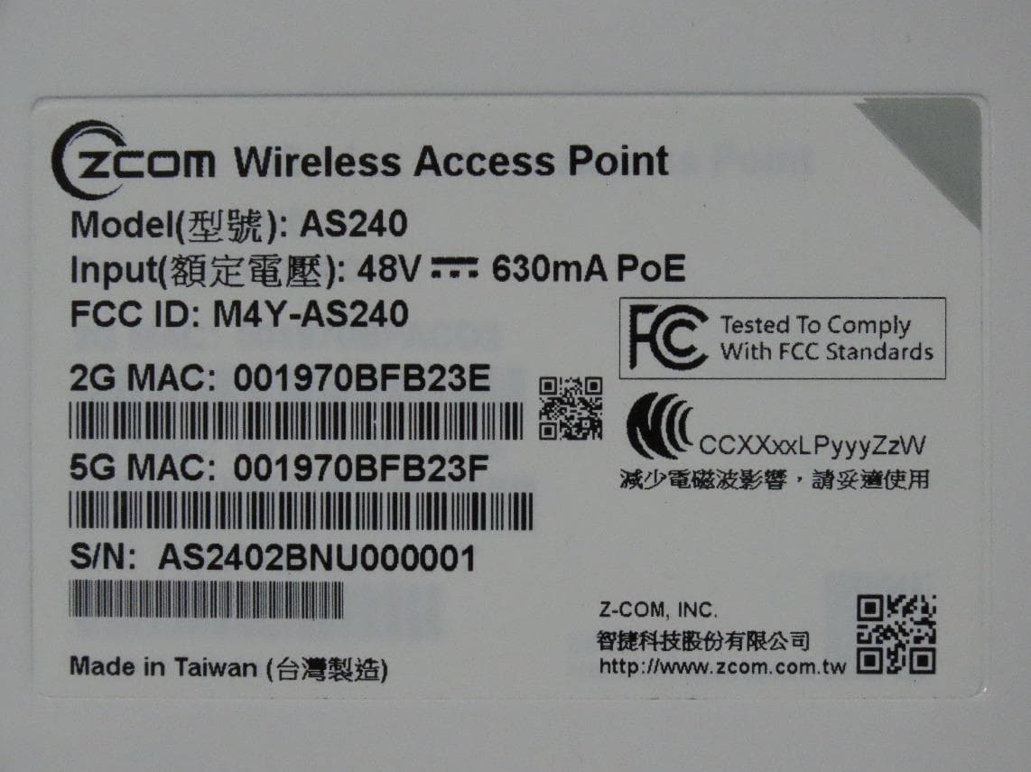
M4Y-AS240
Dec 13, 2022802.11ax Access Point
Equipment Class
DTS - Digital Transmission System
M4Y-AC720M
Aug 14, 2022802.11ac Wireless LAN USB Module
Equipment Class
NII - Unlicensed National Information Infrastructure TX
M4Y-SP230
Feb 21, 2021802.11 ac Wave 2 Access Point
Equipment Class
NII - Unlicensed National Information Infrastructure TX
M4Y-SP220C02
Jan 21, 2020802.11ac Access Point
Equipment Class
NII - Unlicensed National Information Infrastructure TX
M4Y-SP220C03
Jan 20, 20205GHz 11ac Wireless Bridge
Equipment Class
NII - Unlicensed National Information Infrastructure TX