M4Y-XG1020V04Wireless LAN Access Point
Z Com Inc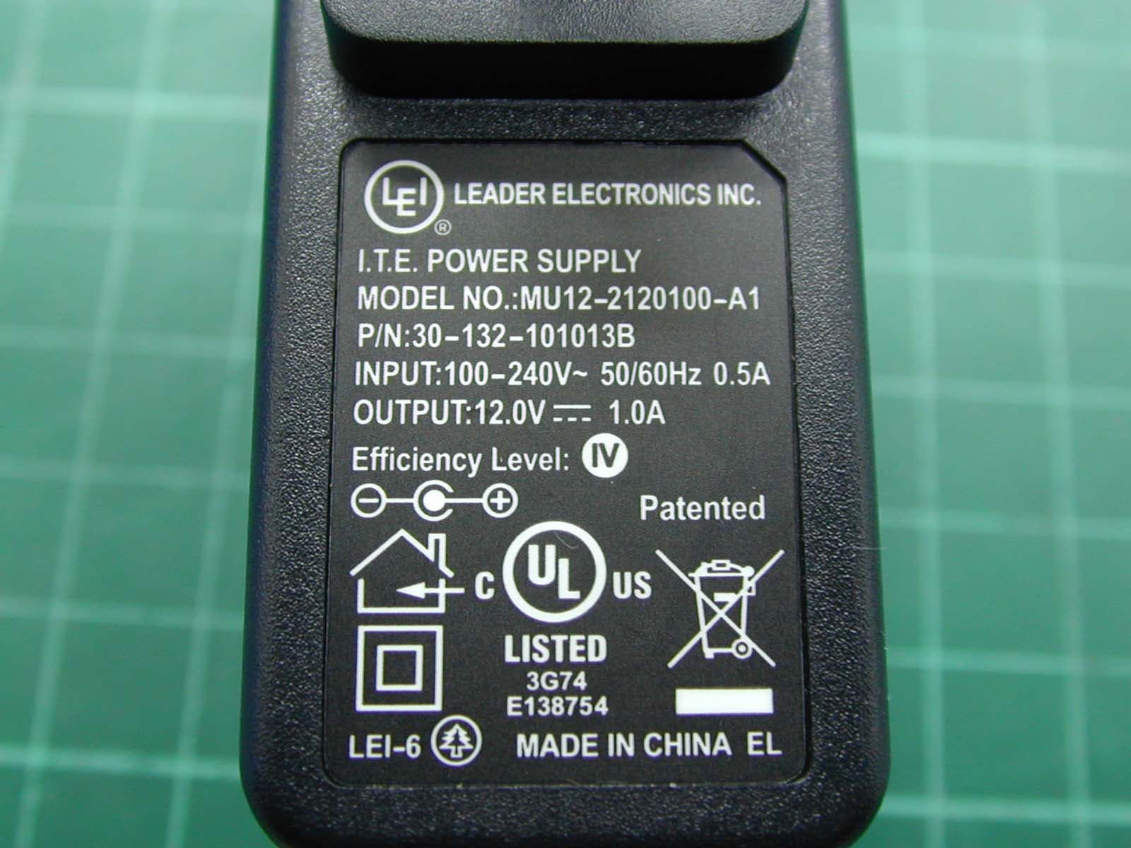
Click to zoom
Application Details
- Equipment Class
- DTS - Digital Transmission System
- Date of Grant
- Apr 19, 2007
- Application Purpose
- Original Equipment
- Date of Application
- Apr 16, 2007
- Equipment Note
- Wireless LAN Access Point
- Frequency Range
- 2412.00000000 - 2462.00000000
- Company
- Z Com Inc
- Country
- Taiwan
Documents & Files
Document Text
Text extracted from the exhibit documents filed with the FCC. Open a document above to read the original.
Users Manual
1 802.11g SOHO Wireless Access Point XG-1020 User’s Manual Version 1.0 – Novenmber 2006 2 Table of Content Chapter 1 Introduction..................................................................................................... 3 1-1 Features and Benefits................................................................................................ 3 1-2 Applications.............................................................................................................. 4 Chapter 2 Hardware Installation..................................................................................... 5 2-1 Package Contents...................................................................................................... 5 2-2 System Requirements ............................................................................................... 5 2-3 Mechanical Description ............................................................................................ 6 2-4 Hardware Installation ............................................................................................... 8 2-5 Safety Notification.................................................................................................... 9 Chapter 3 Configuring your Access Point with the Web-Based User Interface ..........10 3-1 Start-up and Log in ..................................................................................................10 3-1-1 Status....................................................................................................................10 3-1-2 System..................................................................................................................11 3-2 Wireless Setup .........................................................................................................12 3-2-1 Wireless Settings ..................................................................................................12 3-2-1-1 AP Mode ...........................................................................................................12 3-2-1-2 Wireless Client ..................................................................................................16 3-2-1-3 Bridge ...............................................................................................................18 3-2-1-4 AP+Repeater .....................................................................................................21 3-2-2 Security Settings...................................................................................................25 3-2-3 MAC Filter ...........................................................................................................28 3-3 Management ............................................................................................................29 3-3-1 Password Setup ....................................................................................................29 3-3-2 Configuration File ................................................................................................30 3-3-3 F/W Upload..........................................................................................................31 3-3-4 Event Log .............................................................................................................32 Limited Warranty ............................................................................................................. 2 3 Chapter 1 Introduction The 802.11g SOHO Wireless Access Point is an AP and Bridge Mode, 2.4GHz and up to 54Mbps wireless LAN access point. The 802.11g SOHO Wireless Access Point can communicate with other mobile devices enabled for 802.11g standard-based wireless LAN connectivity. Using the card in conjunction with the 802.11g SOHO Wireless Access Point, you can create a wireless network for sharing your broadband cable or DSL Internet access among multiple PCs in and around your home or office and enjoy amazing speed of 54Mbps. This high-speed wireless device simultaneously supports both IEEE 802.11b and 802.11g wireless networks and lets you quickly network multiple PCs and notebooks without laying new cables, and gives users the freedom to roam throughout the workplace and stay connected to corporate resources, e-mail, and the Internet. 1-1 Features and Benefits Technique operating in the unlicensed 2.4GHz ISM band. Support Super-G and Turbo-G: increase the throughput performance. Interoperable with IEEE 802.11g wireless devices. Support AP, Wireless Client, Repeater and Bridge Mode. Enhanced Security: WEP Encryption (64, 128 and 152-bit), 802.1x (EAP-TLS, EAP-TTLS, LEAP, EAP-PEAP), WPA/WPA-PSK, WPA2/WPA2-PSK, Wireless MAC MAC Filter List. Interfaces directly to IEEE 802.3 (10/100-BaseTX RJ-45 LAN port) Fast Ethernet networks. Supports 1, 2, 5.5, 11, 6, 9, 12, 18, 24, 36, 48, 54 and 108 Mbps (Turbo G / Super G) data rates. 4 1-2 Applications The 802.11g SOHO Wireless Access Point offers a fast, reliable, high-speed, and high security solution for wireless clients access to the network in applications like these: 1. Remote access to corporate network information E-mail, file transfer and terminal emulation. 2. Difficult-to-wire environments Historical or old buildings, asbestos installations, and open area where wiring is difficult to deploy. 3. Frequently changing environments Retailers, manufacturers and those who frequently rearrange the workplace and change location. 4. Temporary LANs for special projects or peak time ♦ Trade shows, exhibitions and construction sites where a temporary network will be practical. ♦ Retailers, airline and shipping companies need additional workstations during peak period. ♦ Auditors requiring workgroups at customer sites. 5. Access to database for mobile workers Doctors, nurses, retailers, accessing their database while being mobile in the hospital, retail store or office campus. 6. High security connection The secure wireless network can be i…
Text truncated - open the document above for the full version.
Cover Letter(s)
APPENDIX B Confidentility Letter (Permanent) Attention: Application Examiner Re: Request for confidentiality Applicant: Z-Com, Inc. FCC ID: M4Y-XG1020V04 To whom it may concern, Request is hereby submitted by Z-Com, Inc. to withhold permanently from public review certain portions of the application for equipment certification for the referenced FCC identifiers. This request for confidentiality is made pursuant to 47 CFR 0.457(d) of the FCC Rules. In particular, the following sections of the application are to be kept permanently confidential: • Schematics • Detailed Block diagrams • Detailed Operational/Functional Description Rationale for request for confidentiality: Z-Com, Inc. has invested considerable time and materials in research and development to produce the referenced product. Disclosure of the permanently confidential portions of this application to competitors would not only give them significant competitive advantages in developing similar products, but would also disclose successful implementation of unpublished, leading edge technology developed by us. If you have questions or need further information, please contact the undersigned. Sincerely, EMC Engineer Z-Com, Inc.
Cover Letter(s)
APPENDIX A Lettery of Agency "I, an officer of Z-Com, Inc. do hereby authorize Intertek Testing Services to act on our behalf in front of the Federal Communications Commission with respect to all matters relating to certification of equipment under Part 15 and Part 18 of the FCC Rules until further notice." I further certify that no party (as defined in §1.2002(b) of CFR 47, 1992) to this application, including myself, is subject to a denial of federal benefits, that includes FCC benefits, pursuant to Section 5301 of the Anti-Drug Abuse Act of 1988, 21 U.S.C.,853(a). By Ann Su Signature Printed Title EMC Engineer
Cover Letter(s)
Dear Sir: Our wireless product (802.11g Wireless Lan Access Point) is base on country’s requirement of customer to setup wireless channel. For different country, we have different country code to setup. The country code is fixed and user can’t change it. For example, the user in American can only use channel 1 to channel 11. Best regards. Ann Su EMC engineer
External Photos
Photo 1: External photo of EUT XG-1020 Photo 2: External photo of EUT XG-1020 Photo 3: External photo of Antenna XG-1020 Photo 4: External photo of Adapter MU12-2120100-A1 Photo 5: External photo of Adapter MU12-2120100-A1 Photo 6: External photo of Adapter SL-0106-12V1A-U Photo 7: External photo of Adapter SL-0106-12V1A-U
ID Label/Location Info
27.4mm 47.4mm FCC ID Label Location
Internal Photos
Photo 1: Internal photo of EUT XG-1020 Photo 2: Internal photo of EUT XG-1020 Photo 3: Internal photo of EUT XG-1020 Photo 4: Internal photo of EUT XG-1020 Photo 5: Internal photo of EUT XG-1020
Test Report
FCC ID. : M4Y-XG1020V04 Report No.: EME-070177 Page 1 of 78 EMC TEST REPORT Report No. : EME-070177 Model No. : XG-1020 Issued Date : Mar. 22, 2007 Applicant : Z-Com, Inc. 7F-2, No. 9. Prosperity RD. I Science-Based Industrial, Park Hsinchu, 300 Taiwan Test By : Intertek Testing Services Taiwan Ltd. No. 11, Lane 275, Ko-Nan 1 Street, Chia-Tung Li, Shiang-Shan District, Hsinchu City, Taiwan This test report consists of 78 pages in total. It may be duplicated completely for legal use with the allowance of the applicant. It shall not be reproduced except in full, without the written approval of Intertek Laboratory. The test result(s) in this report only applies to the tested sample(s). Rico Deng Project Engineer Reviewed By Jerry Liu FCC ID. : M4Y-XG1020V04 Report No.: EME-070177 Page 2 of 78 Table of Contents Summary of Tests ..............................................................................................................4 1. General information ......................................................................................................5 1.1 Identification of the EUT ........................................................................................5 1.2 Additional information about the EUT....................................................................5 1.3 Antenna description.................................................................................................6 1.4 Peripherals equipment .............................................................................................6 2. Test specifications .........................................................................................................7 2.1 Test standard............................................................................................................7 2.2 Operation mode .......................................................................................................7 2.3 Test equipment ........................................................................................................8 3. Minimum 6dB Bandwidth test ......................................................................................9 3.1 Operating environment............................................................................................9 3.2 Test setup & procedure............................................................................................9 3.3 Measured data of Minimum 6dB Bandwidth test results ........................................9 4. Maximum Output Power test ......................................................................................17 4.1 Operating environment..........................................................................................17 4.2 Test setup & procedure..........................................................................................17 4.3 Measured data of Maximum Output Power test results ........................................17 5. RF Antenna Conducted Spurious test..........................................................................19 5.1 Operating environment..........................................................................................19 5.2 Test setup & procedure..........................................................................................19 5.3 Measured data of the highest RF Antenna Conducted Spurious test result ..........19 6. Radiated Emission test ................................................................................................41 6.1 Operating environment..........................................................................................41 6.2 Test setup & procedure..........................................................................................41 6.3 Emission limits ......................................................................................................42 6.4 Radiated spurious emission test data.....................................................................43 7. Power Spectrum Density test ......................................................................................51 7.1 Operating environment..........................................................................................51 7.2 Test setup & procedure..........................................................................................51 7.3 Measured data of Power Spectrum Density test results ........................................51 8. Emission on the band edge..........................................................................................59 8.1 Operating environment..........................................................................................59 8.2 Test setup & procedure..........................................................................................59 8.3 Test Result .............................................................................................................60 9. Power Line Conducted Emission test §FCC 15.207 ...................................................69 9.1 Operating environment..........................................................................................69 9.2 Test setup & procedure..........................................................................................69 9.3 Emission limit .......................................................................................................70 9.4 Uncertainty of Conducted Emission .....................................................................70 9.5 Power Line Conducted Emission test data ............................................................71 FCC ID. : M4Y-XG1020V04 Report No.: EME-070177 Page 3 of 78 Additional information ..................................................................................................75 FCC ID. : M4Y-XG1020V04 Report No.: EME-070177 Page 4 of 78 Summary of Tests 802.11g Wireless LAN Access Point - Model: XG-1020 FCC ID: M4Y-XG1020V04 Test Reference Results Minimum 6dB Bandw…
Text truncated - open the document above for the full version.
Test Setup Photos
Photo 1: Radiated Emission Test set-up photo XG-1020 Photo 2: Radiated Emission Test set-up photo XG-1020
Test Setup Photos
Photo 1: Conducted Emission Test Set-up photo XG-1020 Photo 2: Conducted Emission Test Set-up photo XG-1020
Contact Information
Applicant
Jeff jiang(R&D DIV Director)
Technical Contact
Intertek Testing Services Taiwan Ltd.Jerry Liu
[email protected]+886-3-519-1411
11, Ln.275, Ko Nan 1st Street · Hsinchu · Taiwan
Test Firm
Intertek Testing Services Taiwan Ltd.Alpha Liu
Technical Specifications
| # | Rule Parts | Frequency Range | Power Output |
|---|---|---|---|
| 1 | 15C | 2.41 GHz - 2.46 GHz | 180.00 mW |
Other Applications from Z Com Inc
M4Y-AS240
Dec 13, 2022802.11ax Access Point
Equipment Class
DTS - Digital Transmission System
M4Y-AC720M
Aug 14, 2022802.11ac Wireless LAN USB Module
Equipment Class
NII - Unlicensed National Information Infrastructure TX
M4Y-SP230
Feb 21, 2021802.11 ac Wave 2 Access Point
Equipment Class
NII - Unlicensed National Information Infrastructure TX
M4Y-SP220C02
Jan 21, 2020802.11ac Access Point
Equipment Class
NII - Unlicensed National Information Infrastructure TX
M4Y-SP220C03
Jan 20, 20205GHz 11ac Wireless Bridge
Equipment Class
NII - Unlicensed National Information Infrastructure TX