M4Y-XN790V01802.11 b/g/n Wireless USB Card
Z Com Inc
Click to zoom
Application Details
- Equipment Class
- DTS - Digital Transmission System
- Date of Grant
- Aug 08, 2007
- Application Purpose
- Original Equipment
- Date of Application
- Jul 25, 2007
- Equipment Note
- 802.11 b/g/n Wireless USB Card
- Frequency Range
- 2412.00000000 - 2462.00000000
- Company
- Z Com Inc
- Country
- Taiwan
Documents & Files
Document Text
Text extracted from the exhibit documents filed with the FCC. Open a document above to read the original.
Users Manual
1 I I E E E E E E 8 8 0 0 2 2 . . 1 1 1 1 n n W W i i r r e e l l e e s s s s L L A A N N U U S S B B A A d d a a p p t t e e r r Model: XN-790 User’s Manual Version: 1.0 Date of issue: June 6, 2007 2 Federal Communications Commission (FCC) Interference Statement This device, IEEE 802.11n Wireless LAN USB Adapter, complies with Part 15 of the FCC Rules. Operation is subject to the following two conditions: This device may not cause harmful interference. This device must accept any interference received; including interference that may cause undesired operation. This Equipment has been tested and found to comply with the limits for a Class B digital device, pursuant to Part 15 of the FCC rules. These limits are designed to provide reasonable protection against harmful interference in a residential installation. This equipment generates, uses and can radiate radio frequency energy and, if not installed and used in accordance with the instructions, may cause harmful interference to radio communications. However, there is no guarantee that interference will not occur in a particular installation. If this equipment does cause harmful interference to radio or television reception, which can be determined by turning the equipment off and on, the user is encouraged to try to correct the interference by one or more of the following measures: 1. Reorient or relocate the receiving antenna. 2. Increase the separation between the equipment and receiver. 3. Connect the equipment into an outlet on a circuit different from that to which the receiver is connected. 4. Consult the dealer or an experienced radio/TV technician for help. Warning: Changes or modifications to this unit not expressly approved by the party responsible for compliance could void the user authority to operate the equipment. 1. This equipment complies with FCC RF radiation exposure limits set forth for an uncontrolled environment, under 47 CFR 2.1093 paragraph (d)(2). 2. This Transmitter must not be co-located or operating in conjunction with any other antenna or transmitter. CE Statement: 3 Hereby, Company Name (申請或販售公司), declares that this device is in compliance with the essential requirements and other relevant provisions of the R&TTE Directive 1999/5/EC. This device will be sold in the following EEA countries: Austria, Italy, Belgium, Liechtenstein, Denmark, Luxembourg, Finland, Netherlands, France, Norway, Germany, Portugal, Greece, Spain, Iceland, Sweden, Ireland, United Kingdom, Cyprus, Czech Republic, Estonia, Hungary, Latvia, Lithuania, Malta, Slovakia, Poland, Slovenia, Bulgaria, Romania. 依據 低功率電波輻射性電機管理辦法 第十二條 經型式認證合格之低功率射頻電機,非經許可,公司、商號或使用者均不得擅自變更 頻率、加大功率或變更原設計之特性及功能。 第十四條 低功率射頻電機之使用不得影響飛航安全及干擾合法通信;經發現有干擾現象時,應 立即停用,並改善至無干擾時方得繼續使用。前項合法通信,指依電信規定作業之無線電信。低 功率射頻電機須忍受合法通信或工業、科學及醫療用電波輻射性電機設備之干擾。 4 Technical Support The software version of the IEEE 802.11n Wireless LAN USB Adapter is displayed on the utility About window. Users could download the most recent software version from the supplier’s web site or refer to the selling contact for the latest software information. If you have difficulty solving the problem while installing or using the IEEE 802.11n Wireless LAN USB Adapter, please contact the supplier for support. About This Manual IEEE 802.11n Wireless LAN USB Adapter User’s Manual is first published on June 2007. This manual is intended for people who want to configure the IEEE 802.11n Wireless LAN USB Adapter under Windows Vista, Windows XP, and Windows 2000. You should have at least a basic knowledge of TCP/IP networking concepts and topology. 5 Table of Contents Technical Support ........................................................................................................................4 About This Manual .......................................................................................................................4 Table of Contents .........................................................................................................................5 Chapter 1.......................................................................................................................................6 1.1 About your IEEE 802.11n Wireless LAN USB Adapter...................................................6 1.2 Features and Benefits.......................................................................................................6 1.3 Applications.......................................................................................................................7 1.4 Product Kit.........................................................................................................................8 1.5 IEEE 802.11n Wireless LAN USB Adapter LED Indicators.............................................8 Chapter 2.......................................................................................................................................9 2.1 Installation Requirements ................................................................................................9 2.2 Installation .........................................................................................................................9 2.2.1 Install IEEE 802.11n Wireless LAN USB Adapter for Windows Vista ................................. 10 2.2.2 Install IEEE 802.11n Wireless LAN USB Adapter for Windows XP/2000 ........................... 15 Note for Windows XP users .................................................................................................21 Chapter 3.......................................................................................................................................22 3.1 Wireless LAN Overview ..................................................................................................22 3.1.1 SSID ....................................................................................................................................... 22 3.1.2 Channel................................…
Text truncated - open the document above for the full version.
Cover Letter(s)
Confidentility Letter (Permanent) Attention: Application Examiner Re: Request for confidentiality Applicant: Z-Com, Inc. FCC ID: M4Y-XN790V01 To whom it may concern, Request is hereby submitted by Procare International Co. to withhold permanently from public review certain portions of the application for equipment certification for the referenced FCC identifiers. This request for confidentiality is made pursuant to 47 CFR 0.457(d) of the FCC Rules. In particular, the following sections of the application are to be kept permanently confidential: • Schematics • Detailed Block diagrams • Detailed Operational/Functional Description Rationale for request for confidentiality: Procare International Co. has invested considerable time and materials in research and development to produce the referenced product. Disclosure of the permanently confidential portions of this application to competitors would not only give them significant competitive advantages in developing similar products, but would also disclose successful implementation of unpublished, leading edge technology developed by us. If you have questions or need further information, please contact the undersigned. Sincerely, R&D Assistant Engineer
External Photos
Photo 1: External photo of EUT XN-790 Photo 2: External photo of EUT XN-790 Photo 3: External photo of EUT XN-790 Photo 4: External photo of EUT XN-790
Internal Photos
Photo 1: Internal photo of EUT XN-790 Photo 2: Internal photo of EUT XN-790 Photo 3: Internal photo of EUT XN-790 Photo 4: Internal photo of EUT XN-790 Photo 5: Internal photo of EUT XN-790 Photo 6: Internal photo of EUT XN-790
RF Exposure Info
FCC ID. : M4Y-XN790V01 Report No.: EME-070631 Page 1 of 122 Specific Absorption Rate (SAR) Test Report for Z-Com, Inc on the 802.11b/g/n Wireless USB Card Model Number: XN-790 Test Report: EME-070631 Issue date: Jul. 20, 2007 Total No of Pages Contained in this Report: 122 Accredited for testing to FCC Part 15 Tested by: Marx Yan Reviewed by: Kevin Chen Review Date: Jul. 20, 2007 All services undertaken are subject to the following general policy: Reports are submitted for exclusive use of the client to whom they are addressed. Their significance is subject to the adequacy and representative character of the samples and to the comprehensiveness of the tests, examinations or surveys made. This report shall not be reproduced except in full, without written consent of Intertek Testing Services, Taiwan Ltd. 0597 FCC ID. : M4Y-XN790V01 Report No.: EME-070631 Page 2 of 122 Table of Contents 1.0 General information ............................................................................................................................. 3 1.1 Client Information................................................................................................................................ 3 1.2 Equipment under test (EUT) ................................................................................................................ 4 1.3 Test plan reference ............................................................................................................................... 4 1.4 Modifications required for compliance................................................................................................ 4 1.5 Test configuration ................................................................................................................................ 5 1.5.1 Support equipment & EUT antenna position ................................................................................ 5 1.5.2 Test Condition ............................................................................................................................... 6 2.0 SAR Evaluation.................................................................................................................................... 8 2.1 SAR Limits .......................................................................................................................................... 8 2.2 Configuration Photographs .................................................................................................................. 9 2.3 SAR measurement system ................................................................................................................... 19 2.4 SAR measurement system validation .................................................................................................. 21 2.4.1 System Validation result ................................................................................................................ 22 2.4.2 System Performance Check result................................................................................................. 24 2.5 Test Result............................................................................................................................................ 26 3.0 Test Equipment .................................................................................................................................... 28 3.1 Equipment List ..................................................................................................................................... 28 3.2 Tissue Simulating Liquid ..................................................................................................................... 29 3.2.1 Body Tissue Simulating Liquid for evaluation test ....................................................................... 29 3.3 E-Field Probe and 2450 Balanced Dipole Antenna Calibration .......................................................... 30 4.0 Measurement Uncertainty .................................................................................................................... 31 5.0 WARNING LABEL INFORMATION - USA .................................................................................... 33 6.0 REFERENCES..................................................................................................................................... 34 7.0 Document Revision Record ................................................................................................................. 35 APPENDIX A - SAR Evaluation Data ...................................................................................................... 36 APPENDIX B - Photographs ..................................................................................................................... 97 APPENDIX C - E-Field Probe and 2450MHz Balanced Dipole Antenna Calibration Data..................... 99 FCC ID. : M4Y-XN790V01 Report No.: EME-070631 Page 3 of 122 1.0 General information The device was tested at the Intertek Testing Services facility in Hsinchu, Taiwan. The maximum output power declared by the Z-Com. EUT model # XN-790 was evaluated accordance with the requirements for compliance testing defined in FCC OET Bulletin 65, Supplement C (Edition 01-01) and meet the SAR requirement, the phantom employed was the box phantom of 2mm thick in one wall. The total uncertainty for the evaluation of the spatial peak SAR values averaged over a cube of 1g tissue mass had been assessed for this system to be ±20.6%, the dosimetry assessment system INDEXSAR SARA2 was used. In summary, the maximum spatial peak SAR value for the sample device averaged over 1g was found to be: Phantom Position (worst case) SAR 1g , W/kg 2mm thick box phantom wall 802.11b middle channel EUT lei bottom 00mm to phantom 0.518 W/kg In conclusion, the tested Sample device was found to be in compliance with the requirements defined in OET Bulletin 65, Supplement C (Edition 0…
Text truncated - open the document above for the full version.
Test Report
FCC ID. : M4Y-XN790V01 Report No.: EME-070630 Page 1 of 138 EMC TEST REPORT CFR 47 FCC Part 15.247 Report No. : EME-070630 Model No. : XN-790 Issued Date : Jul. 20, 2007 Applicant : Z-Com, Inc. 7F-2, No. 9, Prosperity RD.I Science-Based Industrial, Park Hsinchu, 300 Taiwan Test By : Intertek Testing Services Taiwan Ltd. No. 11, Lane 275, Ko-Nan 1 Street, Chia-Tung Li, Shiang-Shan District, Hsinchu City, Taiwan This test report consists of 138 pages in total. It may be duplicated completely for legal use with the allowance of the applicant. It shall not be reproduced except in full, without the written approval of Intertek Laboratory. The test result(s) in this report only applies to the tested sample(s). Marx Yan Project Engineer Reviewed By Kevin Chen FCC ID. : M4Y-XN790V01 Report No.: EME-070630 Page 2 of 138 1. Summary of Test Data Test/Requirement Description Applicable Rule Result Minimum 6dB Bandwidth 15.247(a)(2) Pass Maximum Output Power 15.247(b) Pass Power Spectral Density 15.247(e) Pass RF Antenna Conducted Spurious 15.247(d) Pass Radiated Spurious Emission 15.247(d), 15.205, 15.209 Pass Emission on the Band Edge 15.247(d) Pass AC Power Line Conducted Emission 15.207 Pass FCC ID. : M4Y-XN790V01 Report No.: EME-070630 Page 3 of 138 2. General Information Identification of the EUT Applicant : Z-Com, Inc. Product : 802.11b/g/n Wireless USB Card Model No. : XN-790 FCC ID. : M4Y-XN790V01 Frequency Range : 2412MHz to 2462MHz for 802.11b, 802.11g, 802.11n 20MHz 2422MHz to 2452MHz for 802.11n 40MHz Channel Number : 11 channels for 802.11b, 802.11g, 802.11n 20MHz : 7 channels for 802.11n 40MHz Rated Power : DC 5V Power Cord : N/A Sample Received : Jun. 25, 2007 Test Date(s) : Jun. 26, 2007 ~ Jul. 18, 2007 Description of EUT The EUT is an 802.11b/g/n Wireless USB Card, it supports two transmission and receive MIMO functions, and was defined as information technology equipment. For more detail features, please refer to User's manual as file name “Installation guide.pdf” FCC ID. : M4Y-XN790V01 Report No.: EME-070630 Page 4 of 138 Antenna description DAC0 The EUT uses a permanently connected antenna. Antenna Gain : -1.31dBi max Antenna Type : PCB Printed Connector Type : N/A DAC1 The EUT uses a permanently connected antenna. Antenna Gain : -1.31dBi max Antenna Type : PCB Printed Connector Type : N/A FCC ID. : M4Y-XN790V01 Report No.: EME-070630 Page 5 of 138 3. Maximum 6dB Bandwidth Name of Test Maximum 6dB Bandwidth Base Standard FCC 15.247 a(2) Tested By: Marx Yan Test Date: Jul. 16, 2007 Test Equipment: EC365 Test Result: Complies Test Method: See Appendix A Measurement Data: See Table & plots below Note: The EUT was tested while in a continuous transmit mode. The EUT was tuned to a low, middle and high channel. Table1. Maximum 6dB Bandwidth 6dB Bandwidth (MHz) Mode Channel Frequency (MHz) DAC0 DAC1 Min. Limit (MHz) Pass/Fail 1 2412 12.56 12.56 0.5 Pass 6 2437 12.72 12.72 0.5 Pass 802.11b 11 2462 12.72 12.72 0.5 Pass 1 2412 16.80 16.80 0.5 Pass 6 2437 16.80 16.80 0.5 Pass 802.11g 11 2462 16.80 16.80 0.5 Pass 1 2412 18.00 17.92 0.5 Pass 6 2437 17.92 17.92 0.5 Pass 802.11n 20MHz 11 2462 18.00 17.92 0.5 Pass 3 2422 36.80 36.80 0.5 Pass 6 2437 36.80 36.80 0.5 Pass 802.11n 40MHz 9 2452 36.80 36.80 0.5 Pass FCC ID. : M4Y-XN790V01 Report No.: EME-070630 Page 6 of 138 DAC0: 6dB Bandwidth @ 802.11b mode channel 1 DAC0: 6dB Bandwidth @ 802.11b mode channel 6 FCC ID. : M4Y-XN790V01 Report No.: EME-070630 Page 7 of 138 DAC0: 6dB Bandwidth @ 802.11b mode channel 11 DAC0: 6dB Bandwidth @ 802.11g mode channel 1 FCC ID. : M4Y-XN790V01 Report No.: EME-070630 Page 8 of 138 DAC0: 6dB Bandwidth @ 802.11g mode channel 6 DAC0: 6dB Bandwidth @ 802.11g mode channel 11 FCC ID. : M4Y-XN790V01 Report No.: EME-070630 Page 9 of 138 DAC0: 6dB Bandwidth @ draft 802.11n 20MHz mode channel 1 DAC0: 6dB Bandwidth @ draft 802.11n 20MHz mode channel 6 FCC ID. : M4Y-XN790V01 Report No.: EME-070630 Page 10 of 138 DAC0: 6dB Bandwidth @ draft 802.11n 20MHz mode channel 11 DAC0: 6dB Bandwidth @ draft 802.11n 40MHz mode channel 3 FCC ID. : M4Y-XN790V01 Report No.: EME-070630 Page 11 of 138 DAC0: 6dB Bandwidth @ draft 802.11n 40MHz mode channel 6 DAC0: 6dB Bandwidth @ draft 802.11n 40MHz mode channel 9 FCC ID. : M4Y-XN790V01 Report No.: EME-070630 Page 12 of 138 DAC1: 6dB Bandwidth @ 802.11b mode channel 1 DAC1: 6dB Bandwidth @ 802.11b mode channel 6 FCC ID. : M4Y-XN790V01 Report No.: EME-070630 Page 13 of 138 DAC1: 6dB Bandwidth @ 802.11b mode channel 11 DAC1: 6dB Bandwidth @ 802.11g mode channel 1 FCC ID. : M4Y-XN790V01 Report No.: EME-070630 Page 14 of 138 DAC1: 6dB Bandwidth @ 802.11g mode channel 6 DAC1: 6dB Bandwidth @ 802.11g mode channel 11 FCC ID. : M4Y-XN790V01 Report No.: EME-070630 Page 15 of 138 DAC1: 6dB Bandwidth @ draft 802.11n 20MHz mode channel 1 DAC1: 6dB Bandwidth @ draft 802.11n 20MHz mode channel 6 FCC ID. : M4Y-XN790V01 Report No.: EME-070630 Page 16 of 138 DAC1: 6dB Bandwidth @ draft 802.11n 20MHz mode channel 11 DAC1: 6dB Bandwidth @ draft 802.11n 40MHz mode channel 3 FCC ID. : M4Y-XN790V01 Report No.: EME-070630 Page 17 of 138 DAC1: 6dB Bandwidth @ draft 802.11n 40MHz mode channel 6 DAC1: 6dB Bandwidth @ draft 802.11n 40MHz mode channel 9 FCC ID. : M4Y-XN790V01 Report No.: EME-070630 Page 18 of 138 4. 99% Occupied Bandwidth Name of Test 99% Occupied Bandwidth Base Standard None; for reporting purposes only Tested By: Marx Yan Test Date: Jul. 18, 2007 Test Equipment: EC365 Test Result: Complies Test Method: See Appendix A Measurement Data: See Table & plots below Note: The EUT was tested while in a continuous transmit mode. The EUT was tuned to a low, middle and high channel. Table2. 99% Occupied Bandwidth 99% Bandwidth (MHz) Mode Channel Frequency (MHz) DAC0 DAC1 1 2412 14.99 14.91 6 2437 14.91 14.99 802.11b 11 2462 14.91 14.99 1 2412 16.51 16.43 6 2437 16.51 16.51 802.11g 11 2462 16.51 16.51 1 2412 17.64 17.64 6 2437 17.64 17.64 802.11n 20MHz 11 2462 17.64 17.64 3 2422 36.07 36.07 6 2437 36.07 36.07 802…
Text truncated - open the document above for the full version.
Test Setup Photos
Photo 1: Conducted Emission Test Set-up photo XN-790 Photo 2: Conducted Emission Test Set-up photo XN-790 Photo 3: Conducted Emission Test Set-up photo XN-790
Test Setup Photos
Photo 1: Radiated Emission Test set-up photo XN-790 Photo 2: Radiated Emission Test set-up photo XN-790
Contact Information
Applicant
Jeff jiang(R&D DIV Director)
Technical Contact
Intertek Testing Services Taiwan Ltd.Kevin Chen
[email protected]886 3 519 1411 x309
11 ln, 275 Ko Tze Nan 1st, Chia-Tung Li · Hsinchu, · Taiwan
Test Firm
Intertek Testing Services Taiwan Ltd.Alpha Liu
Technical Specifications
| # | Rule Parts | Frequency Range | Power Output |
|---|---|---|---|
| 1 | 15C | 2.41 GHz - 2.46 GHz | 384.59 mW |
Other Applications from Z Com Inc
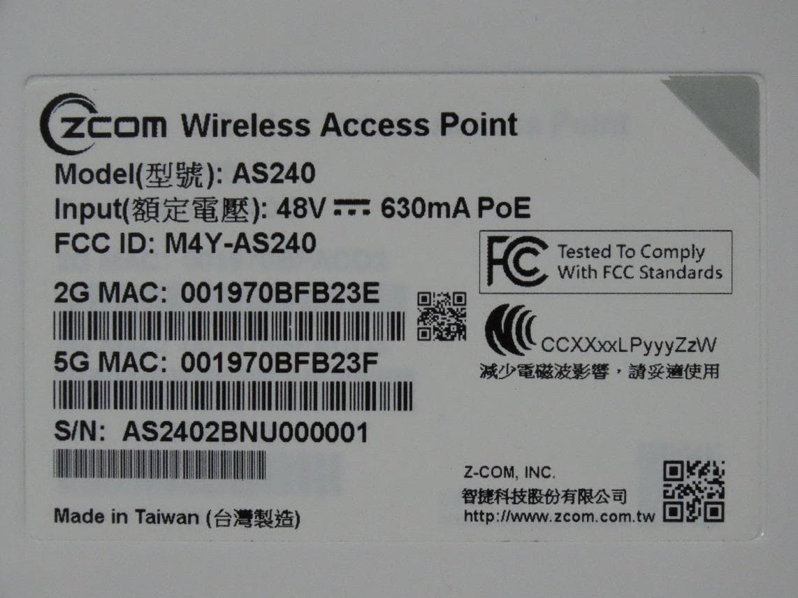
M4Y-AS240
Dec 13, 2022802.11ax Access Point
Equipment Class
DTS - Digital Transmission System
M4Y-AC720M
Aug 14, 2022802.11ac Wireless LAN USB Module
Equipment Class
NII - Unlicensed National Information Infrastructure TX
M4Y-SP230
Feb 21, 2021802.11 ac Wave 2 Access Point
Equipment Class
NII - Unlicensed National Information Infrastructure TX
M4Y-SP220C02
Jan 21, 2020802.11ac Access Point
Equipment Class
NII - Unlicensed National Information Infrastructure TX
M4Y-SP220C03
Jan 20, 20205GHz 11ac Wireless Bridge
Equipment Class
NII - Unlicensed National Information Infrastructure TX