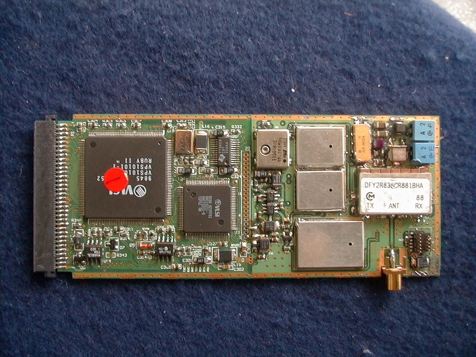
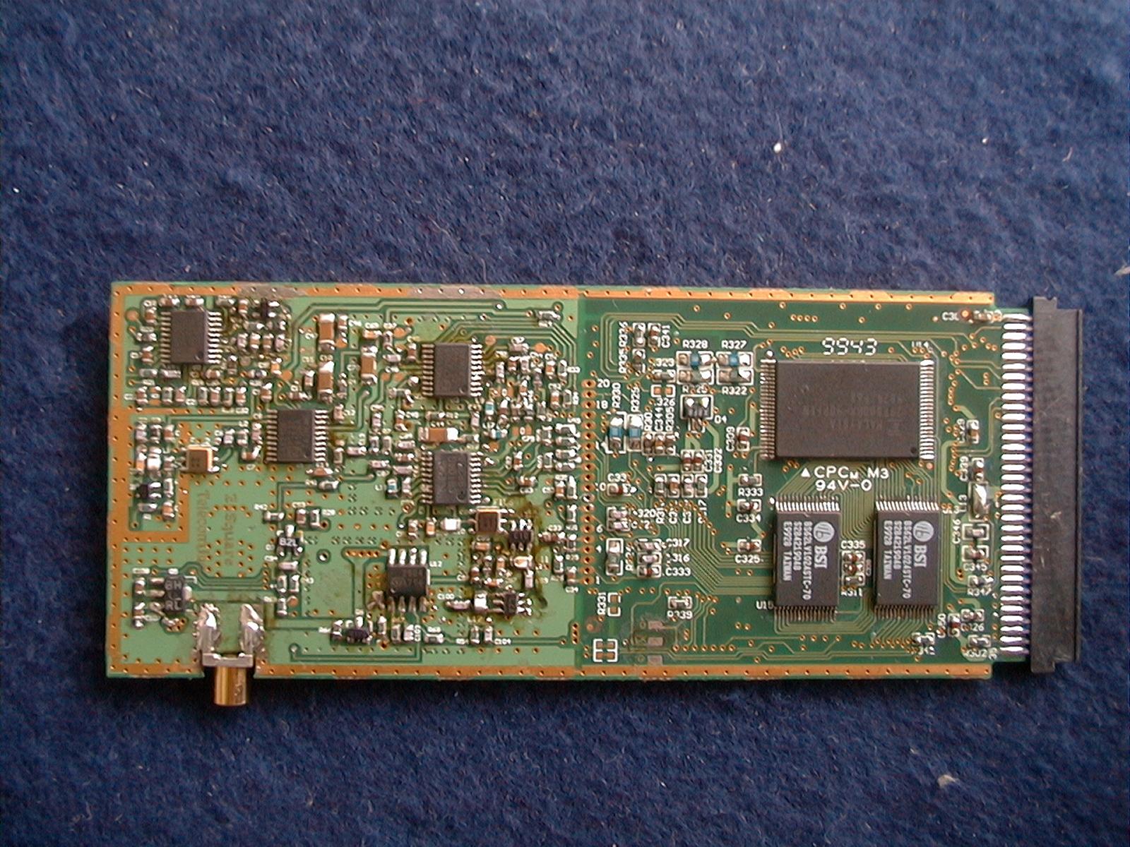
M4Y-ZCARD210PCMCIA CDPD transceiver
Z Com Inc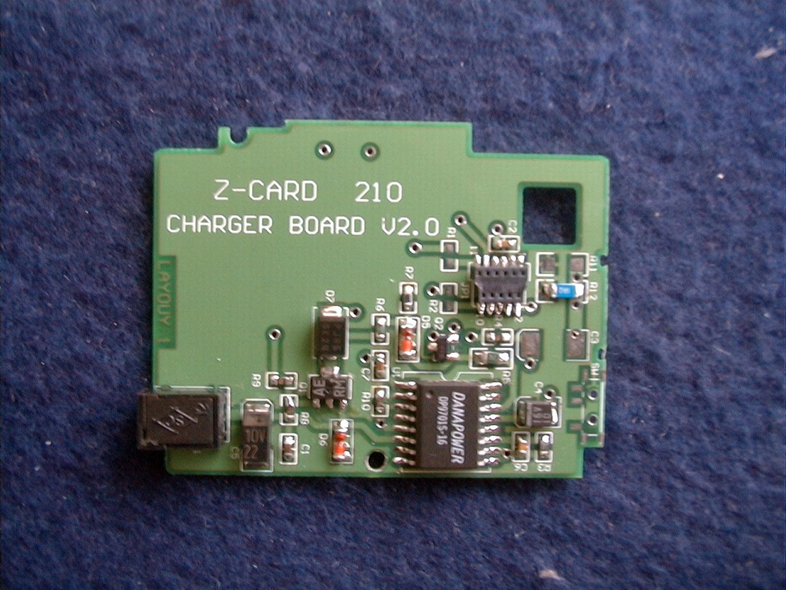
Click to zoom
Application Details
- Equipment Class
- TNB - Licensed Non-Broadcast Station Transmitter
- Date of Grant
- Aug 31, 2000
- Application Purpose
- Original Equipment
- Date of Application
- Feb 01, 2000
- Equipment Note
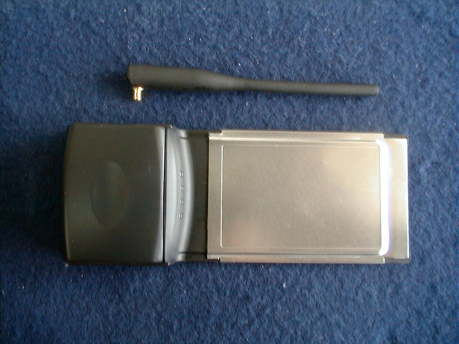
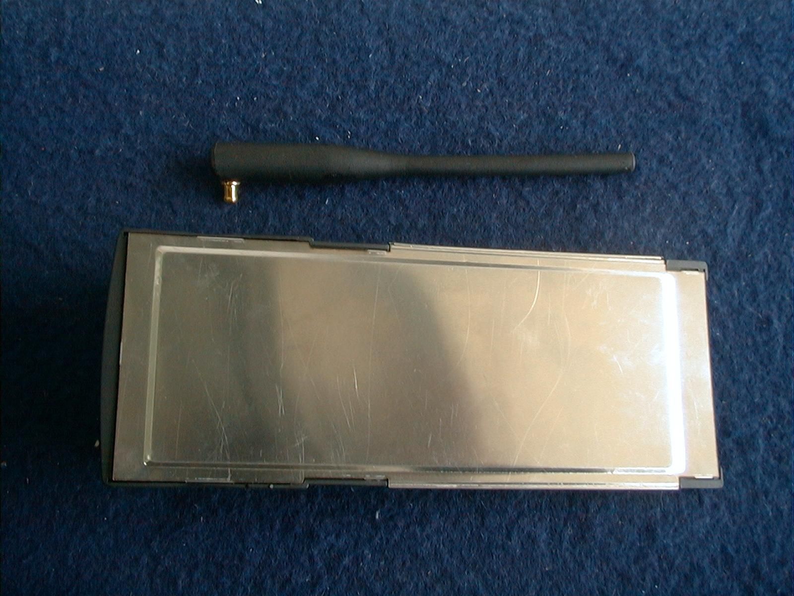
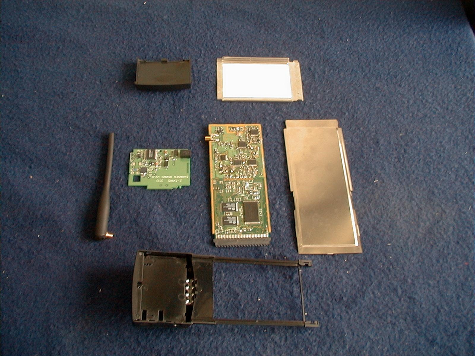
- PCMCIA CDPD transceiver
- Frequency Range
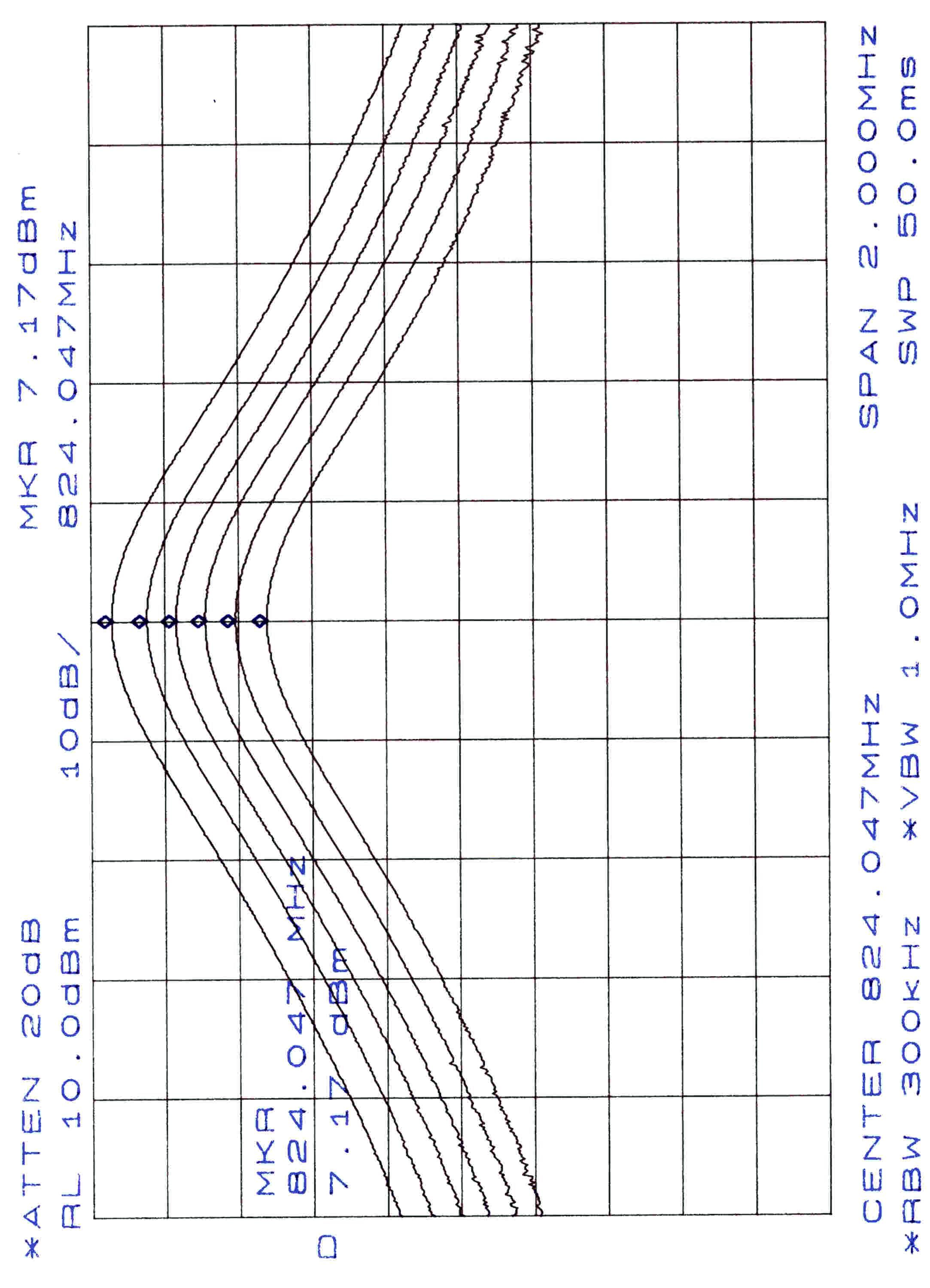
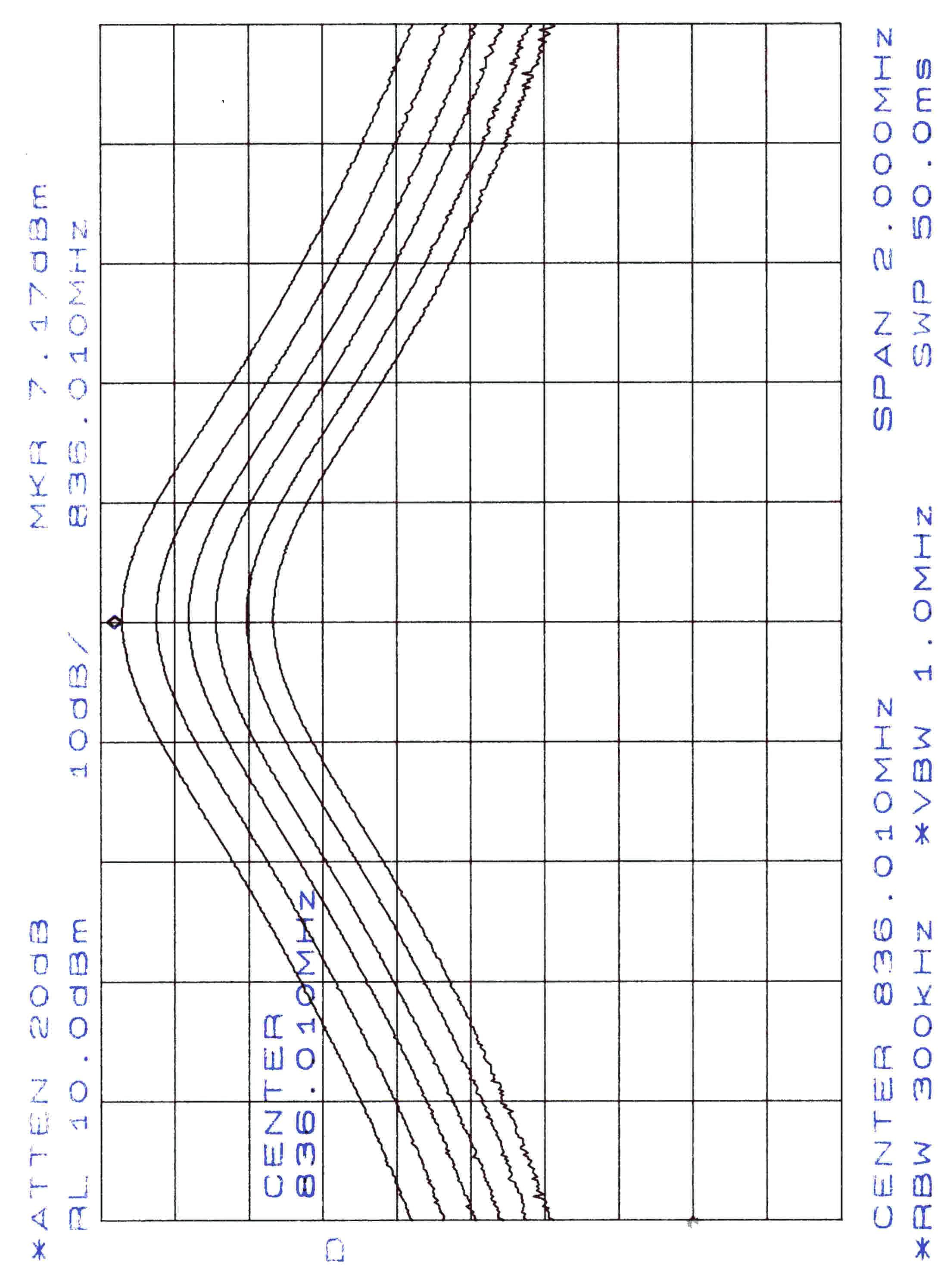
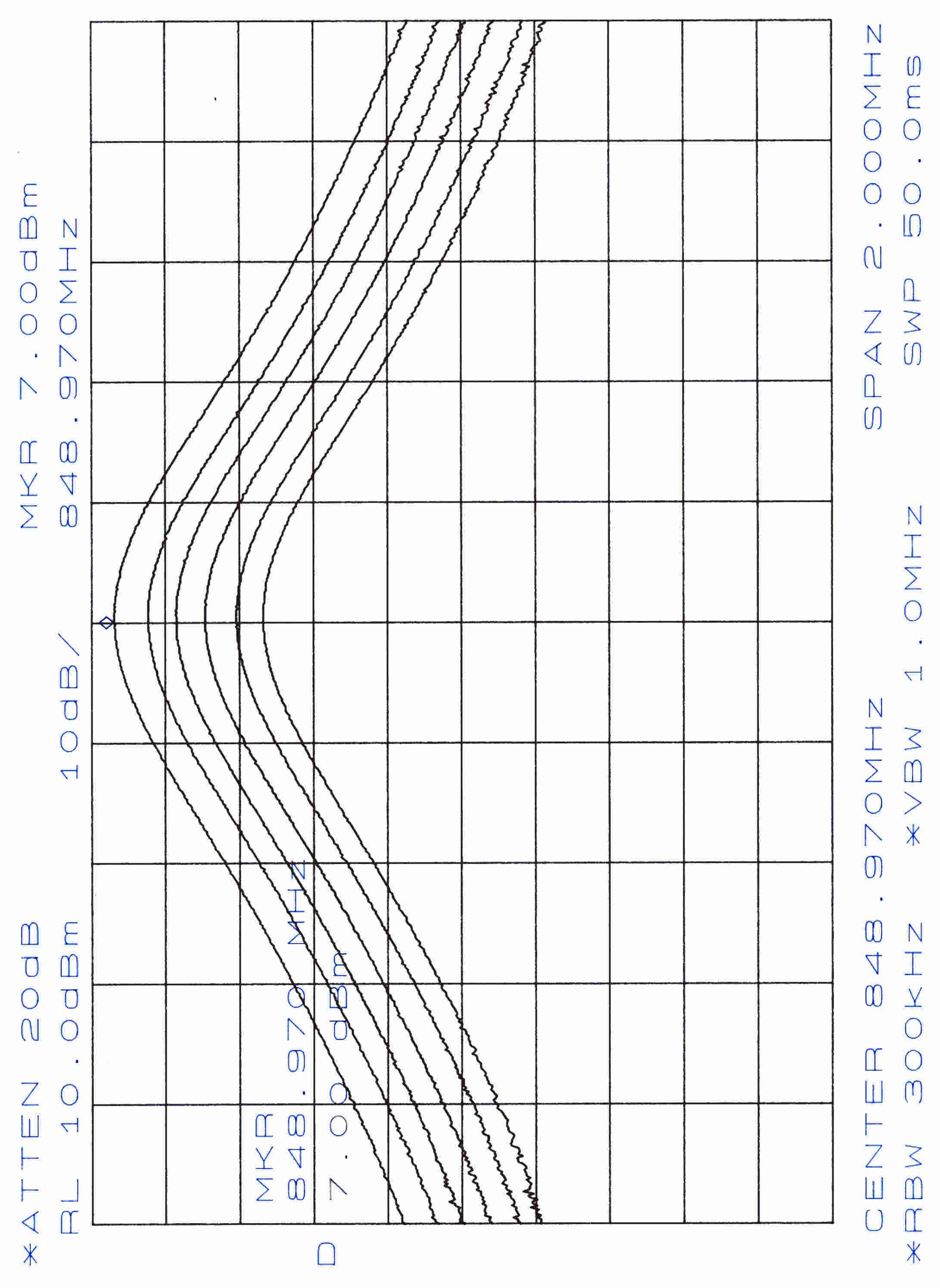
- 824.04000000 - 848.97000000
- Company
- Z Com Inc
- Country
- Taiwan
Documents & Files
Select a file to view
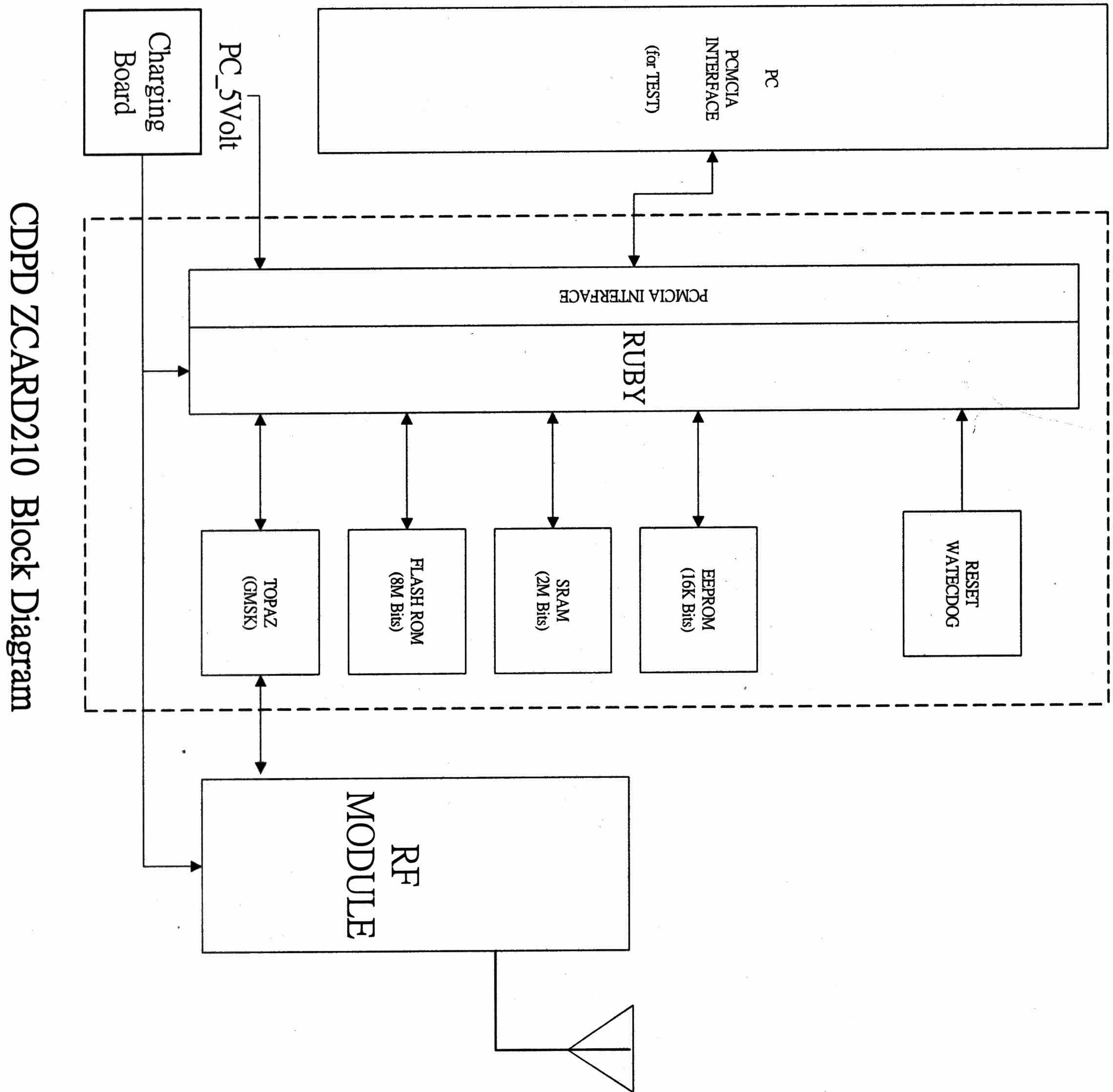
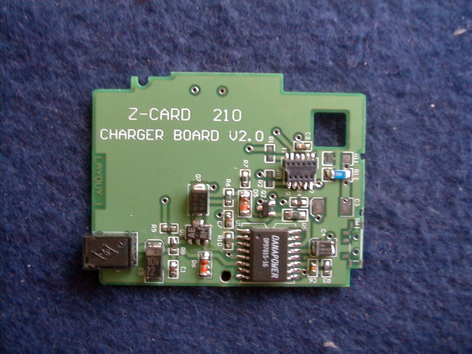
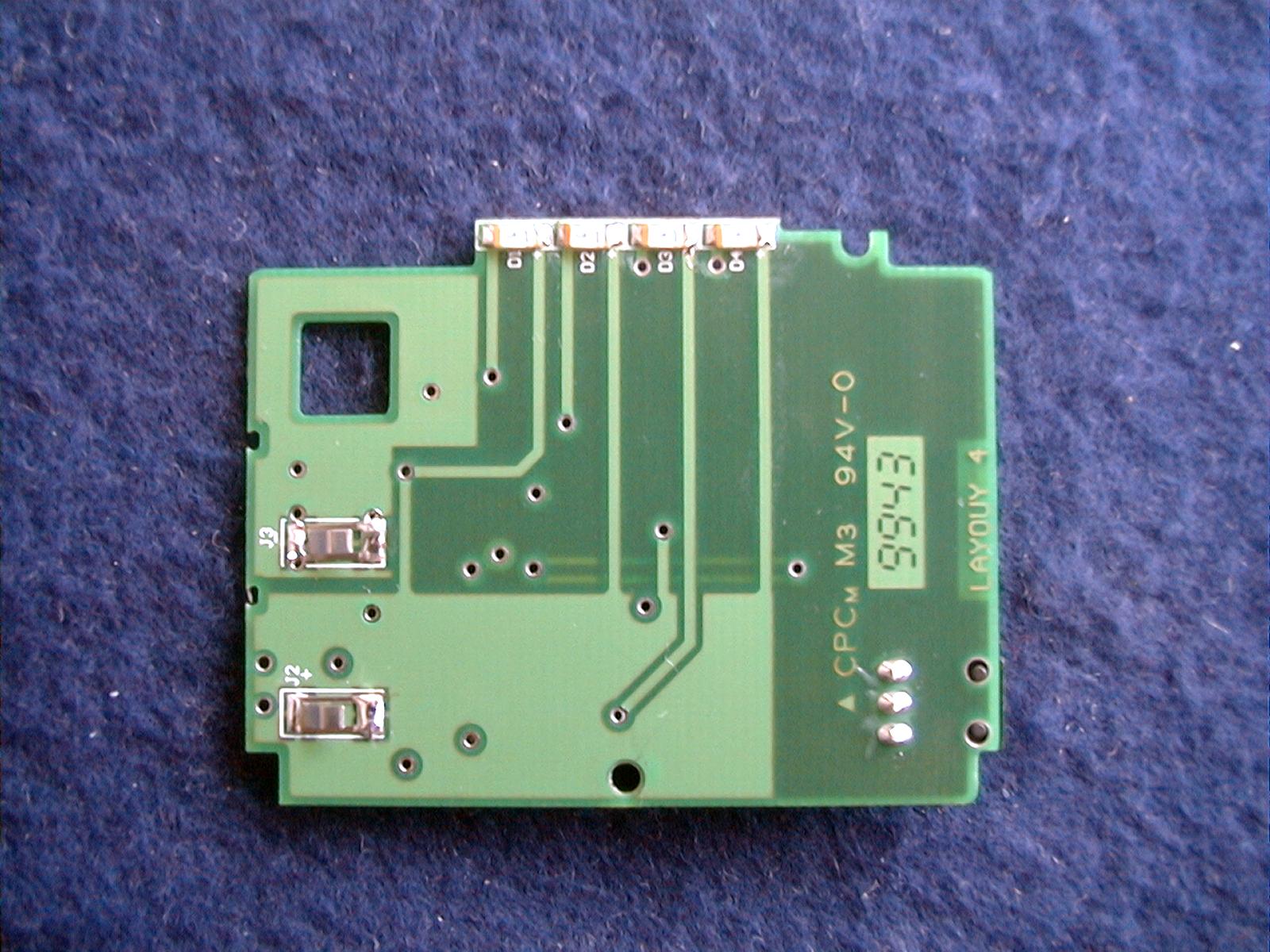
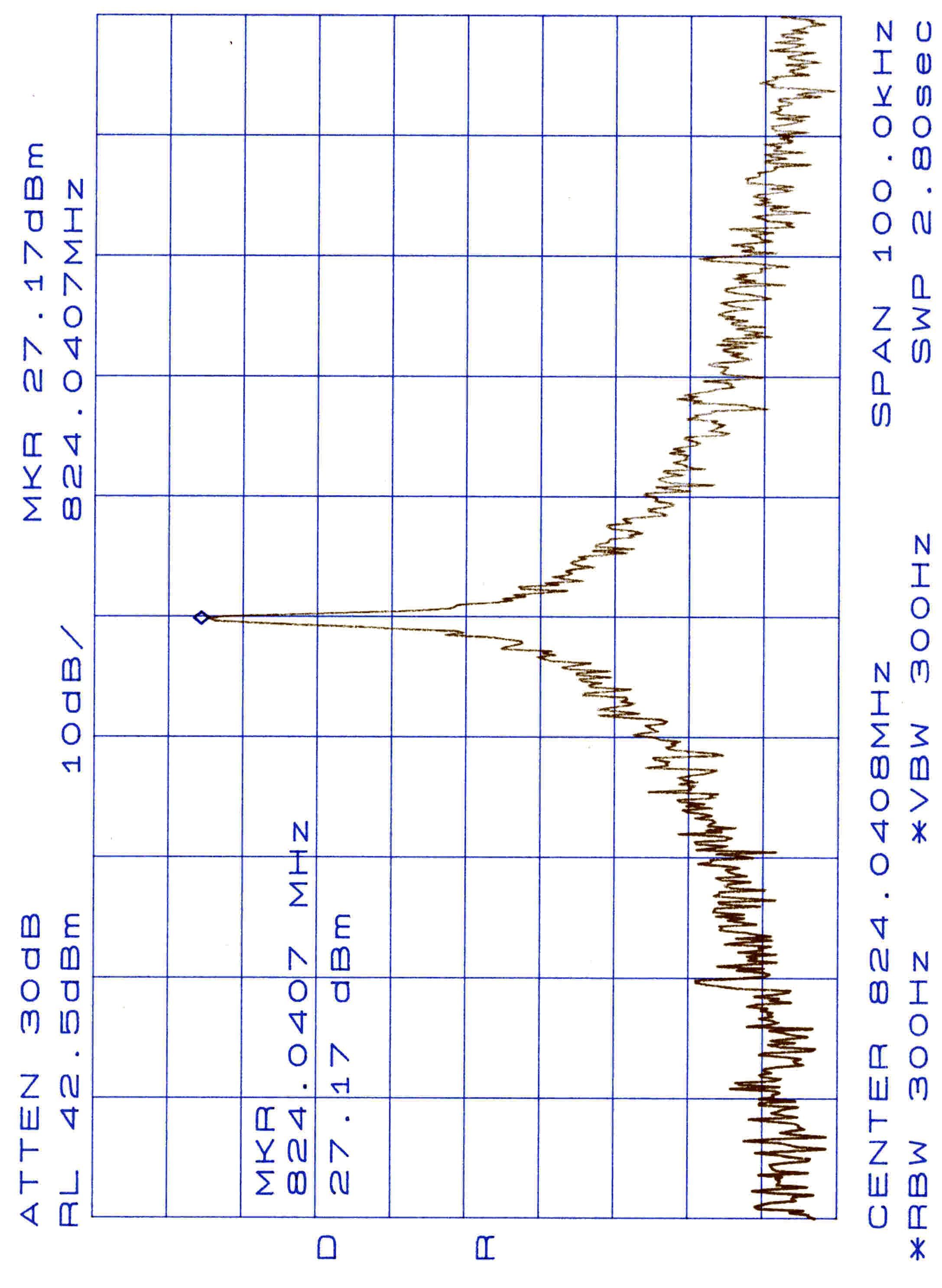
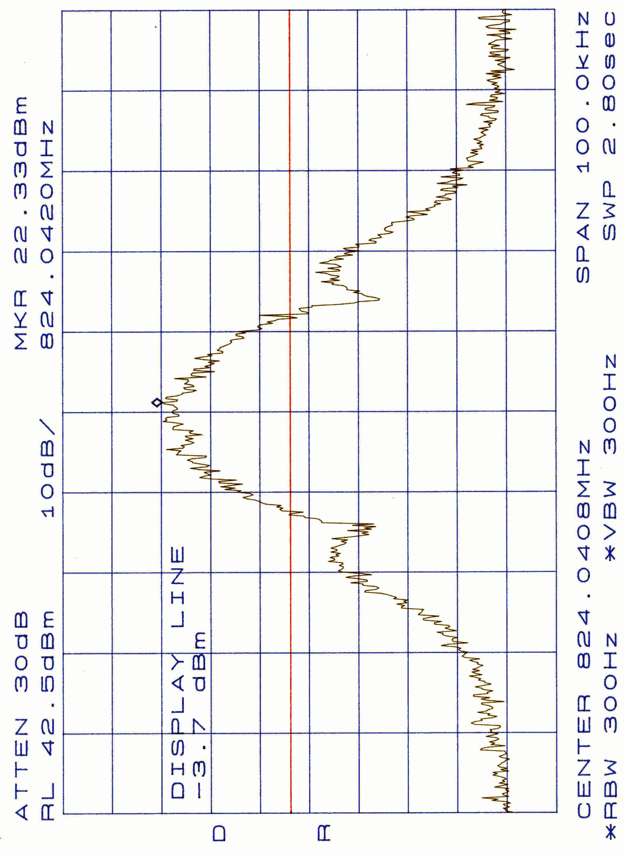
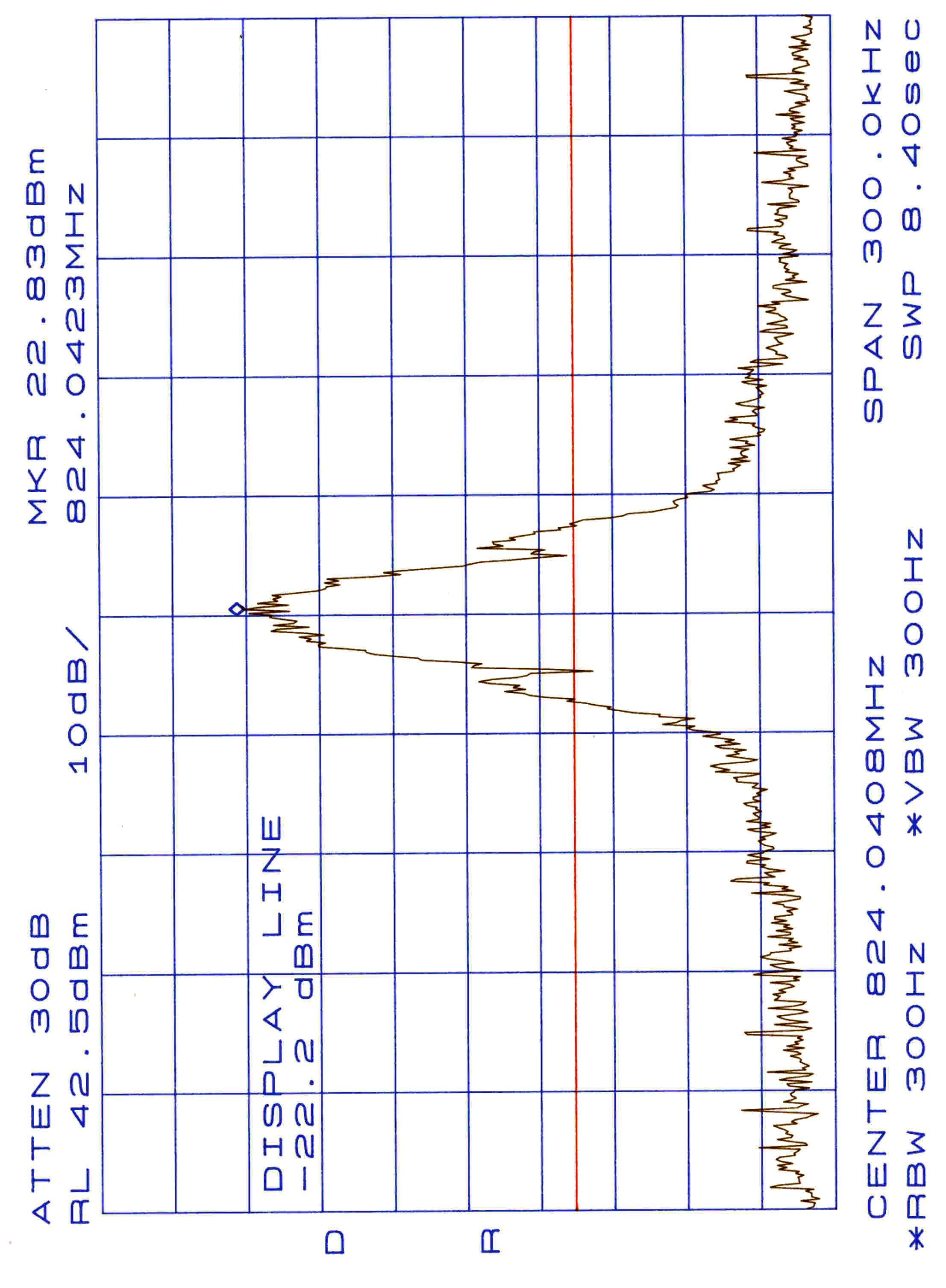
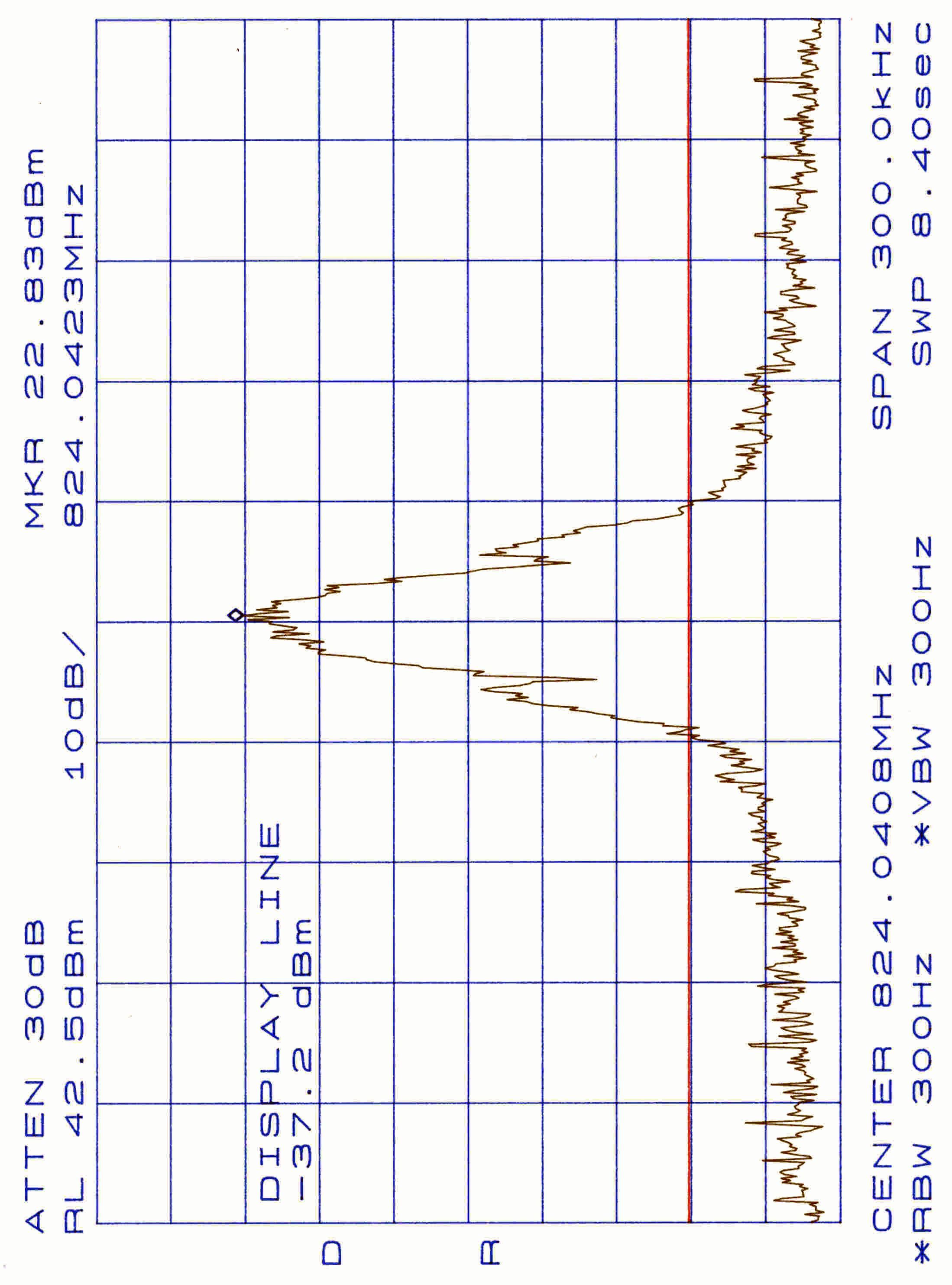
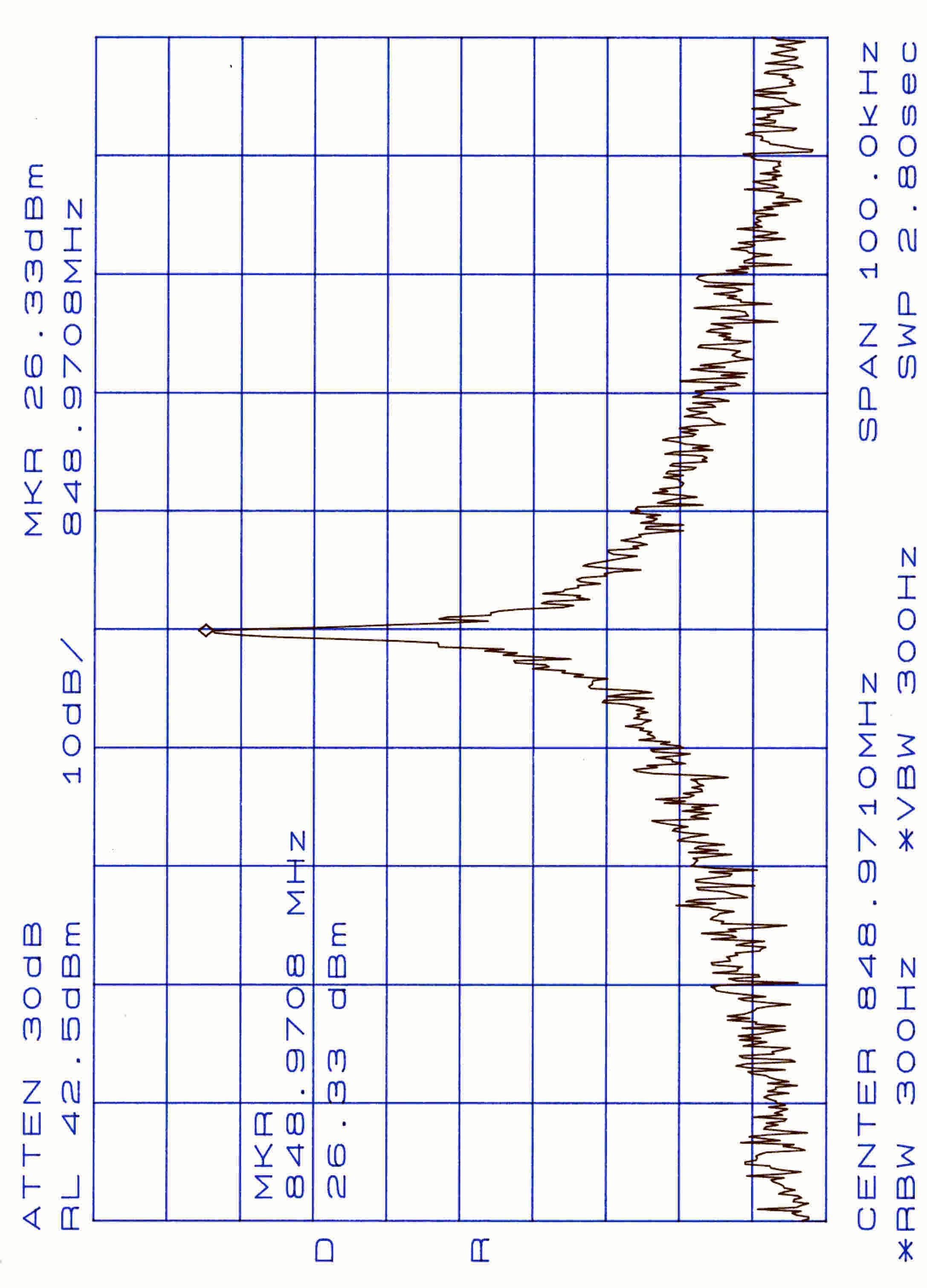
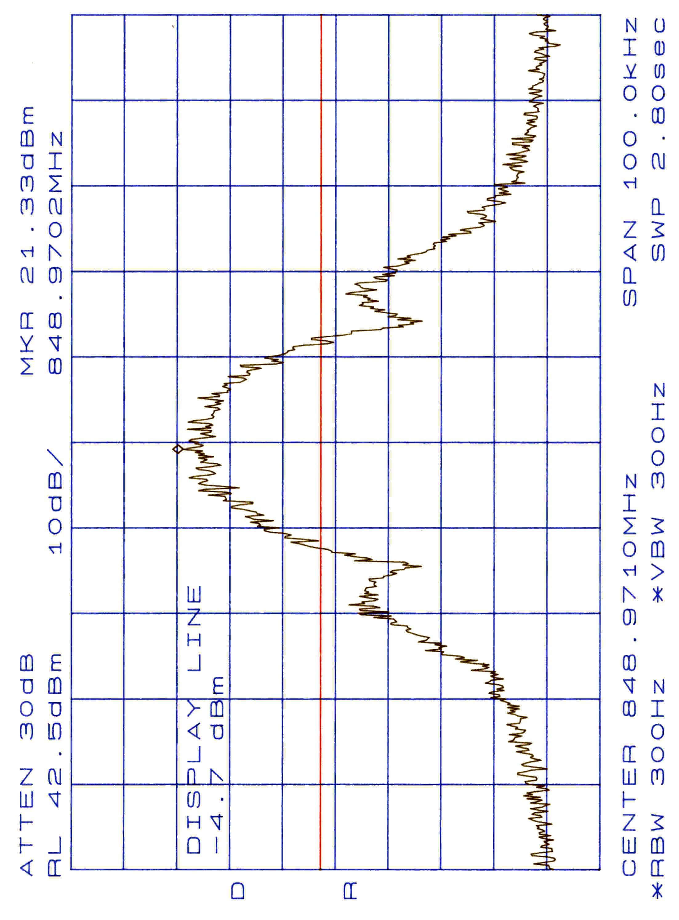
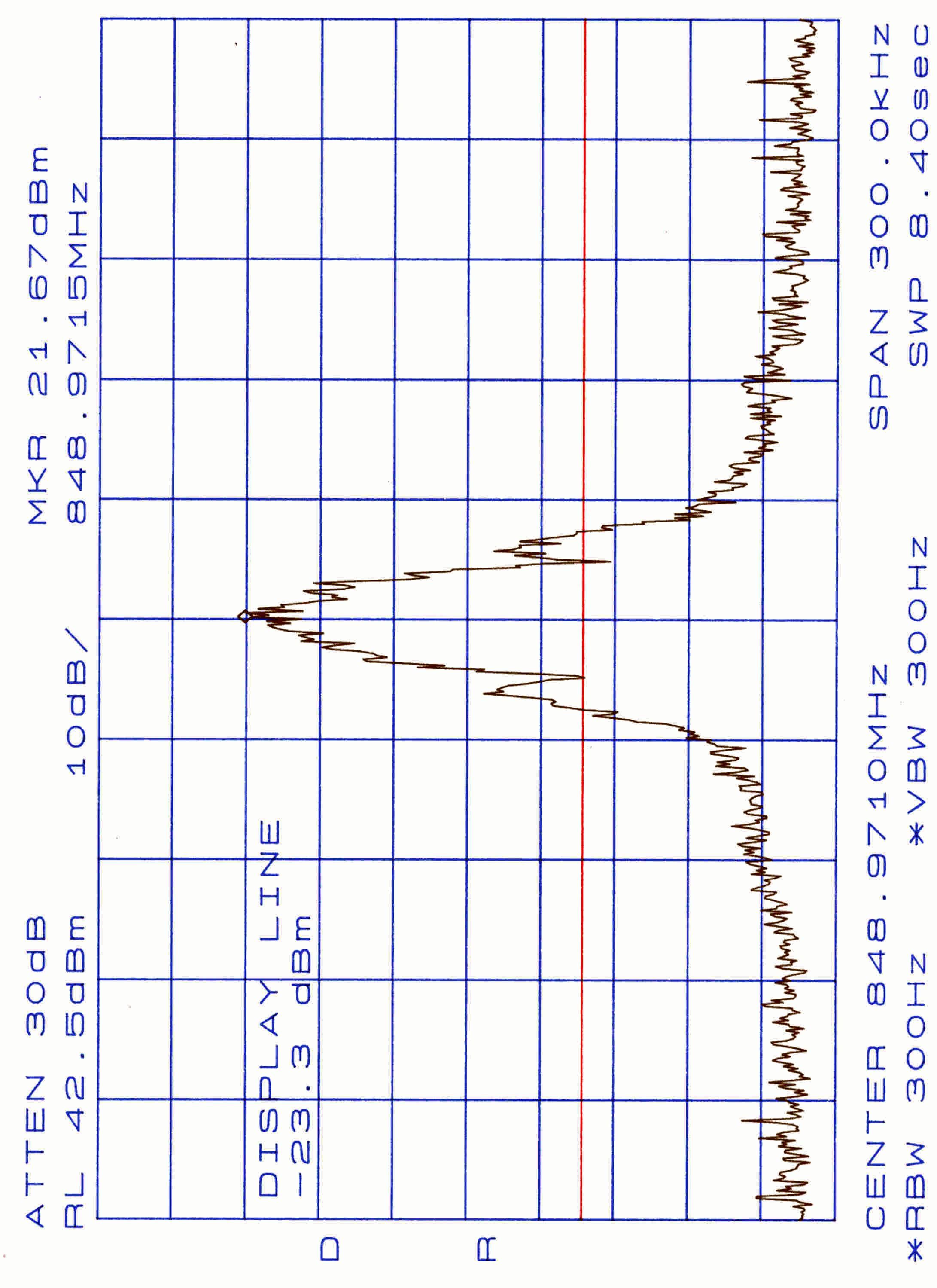
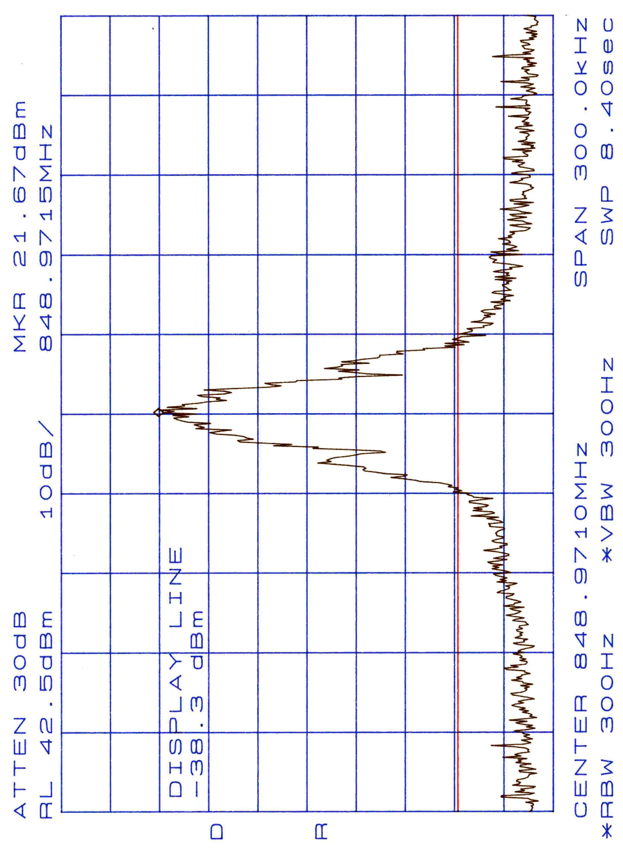
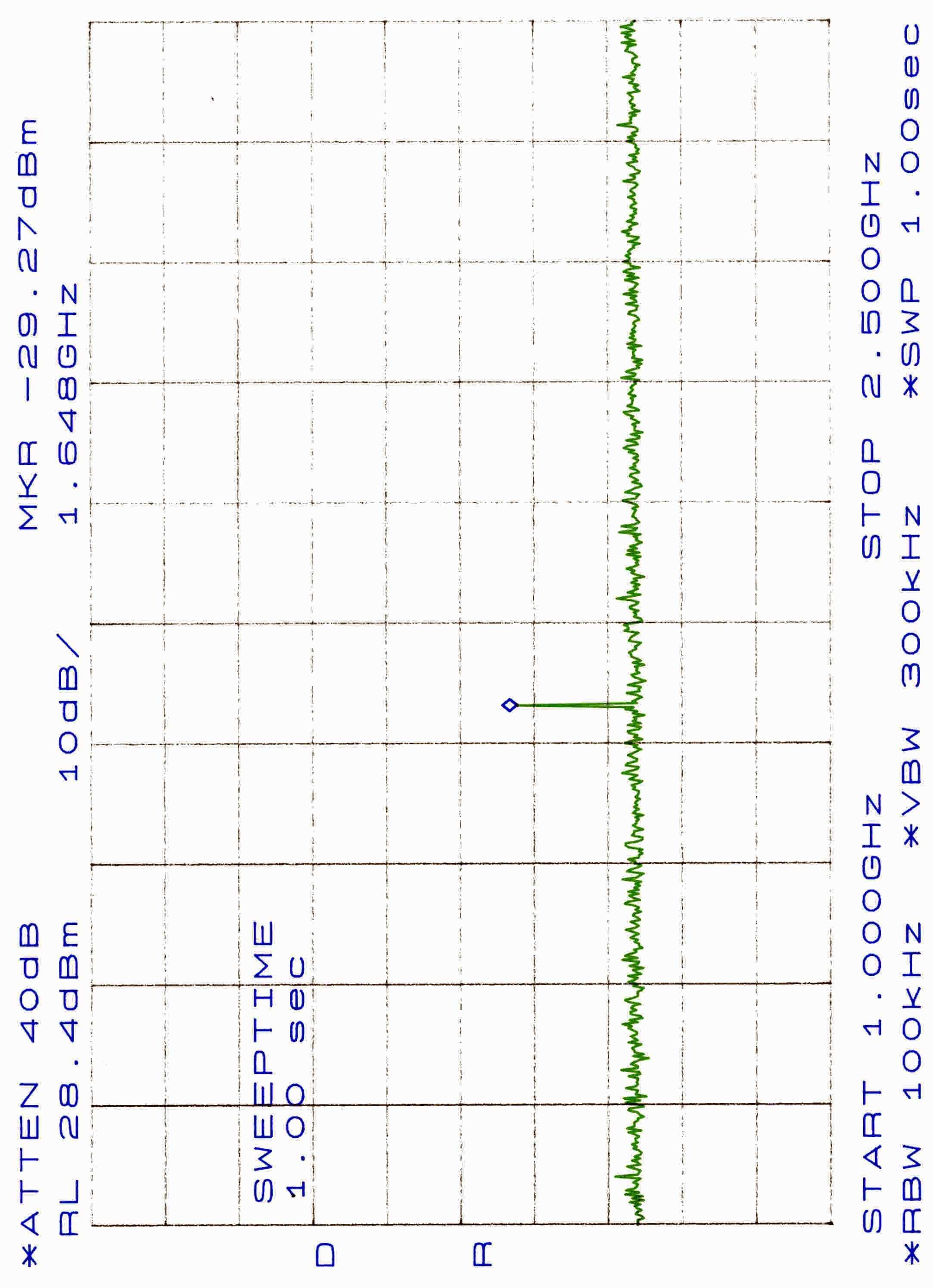
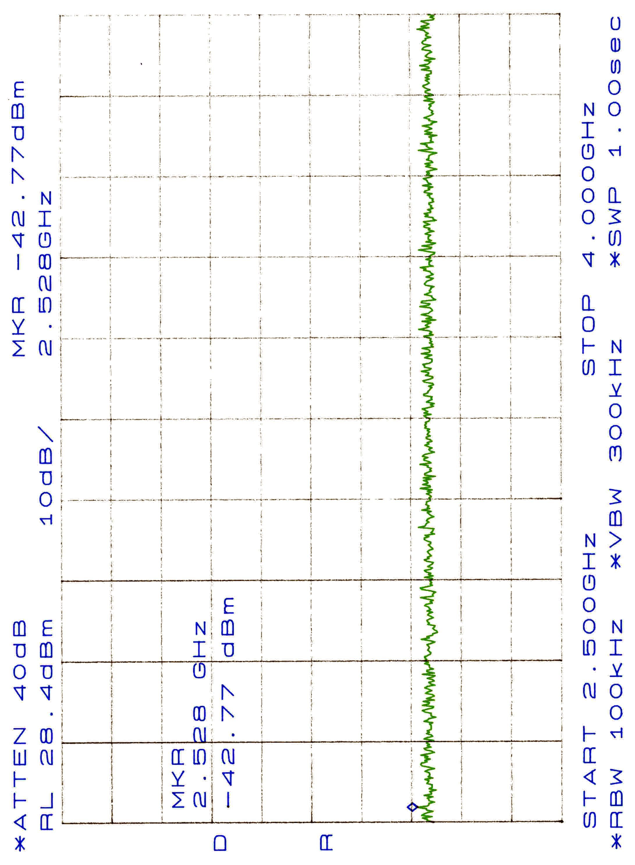
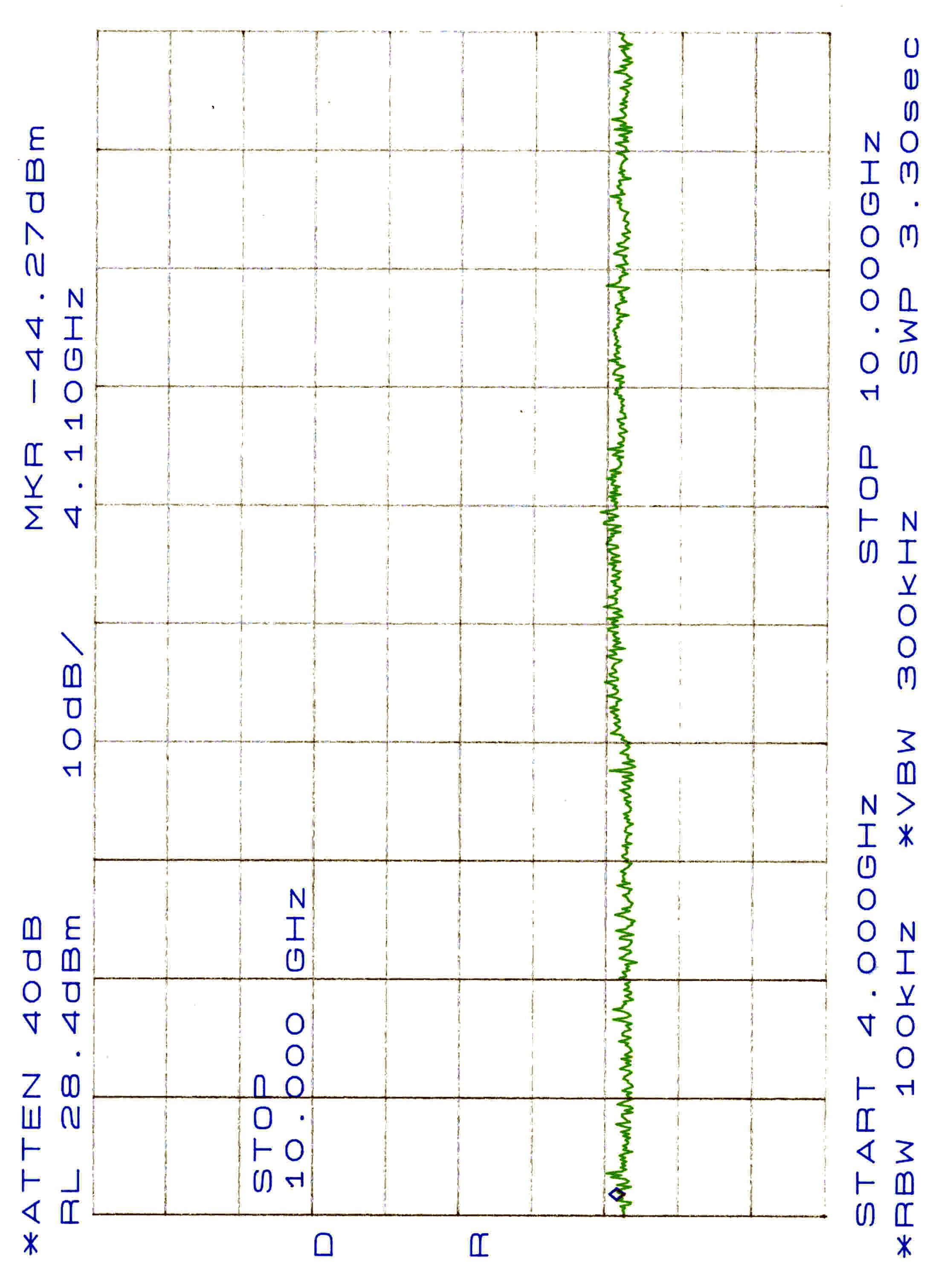
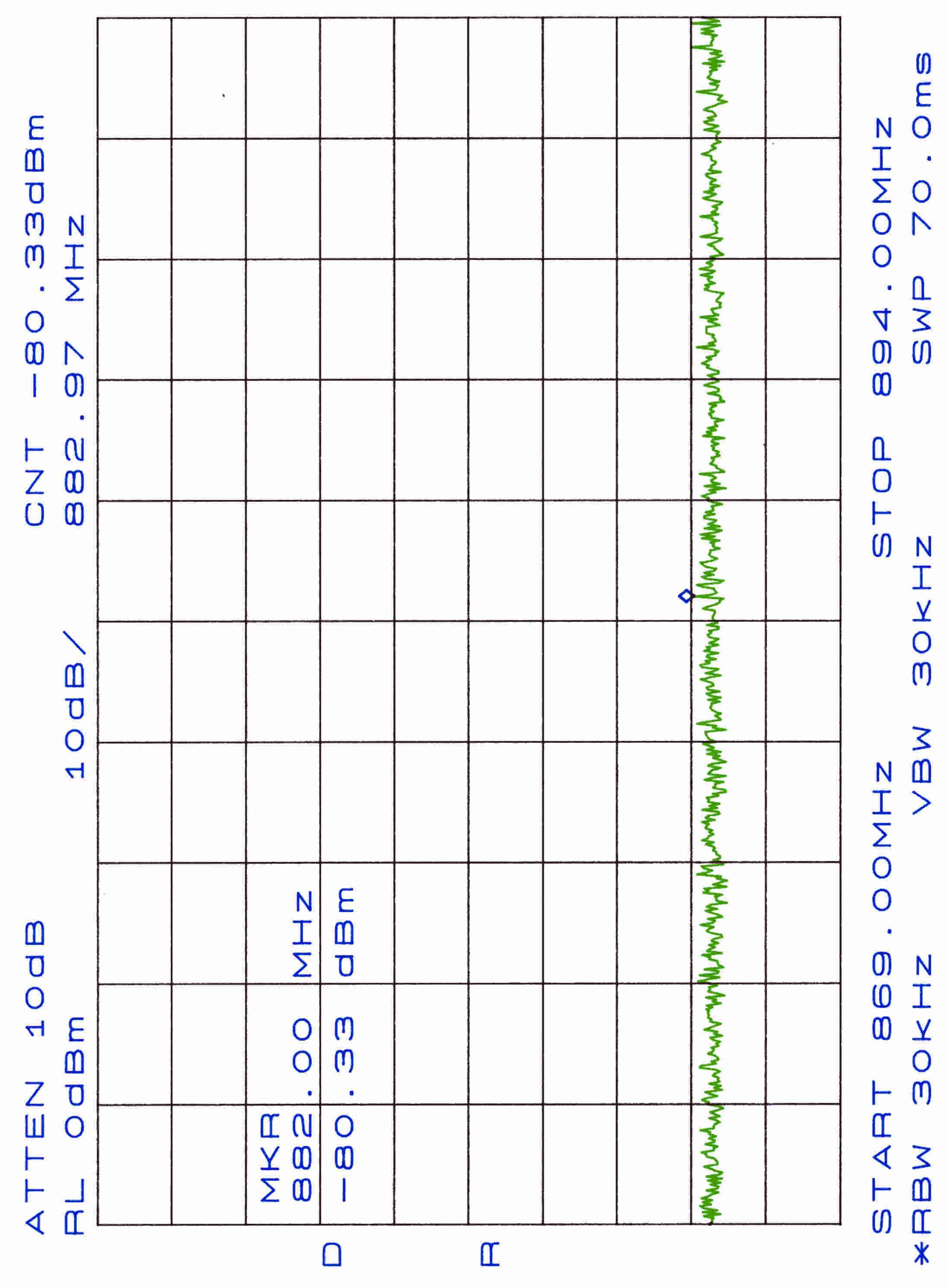

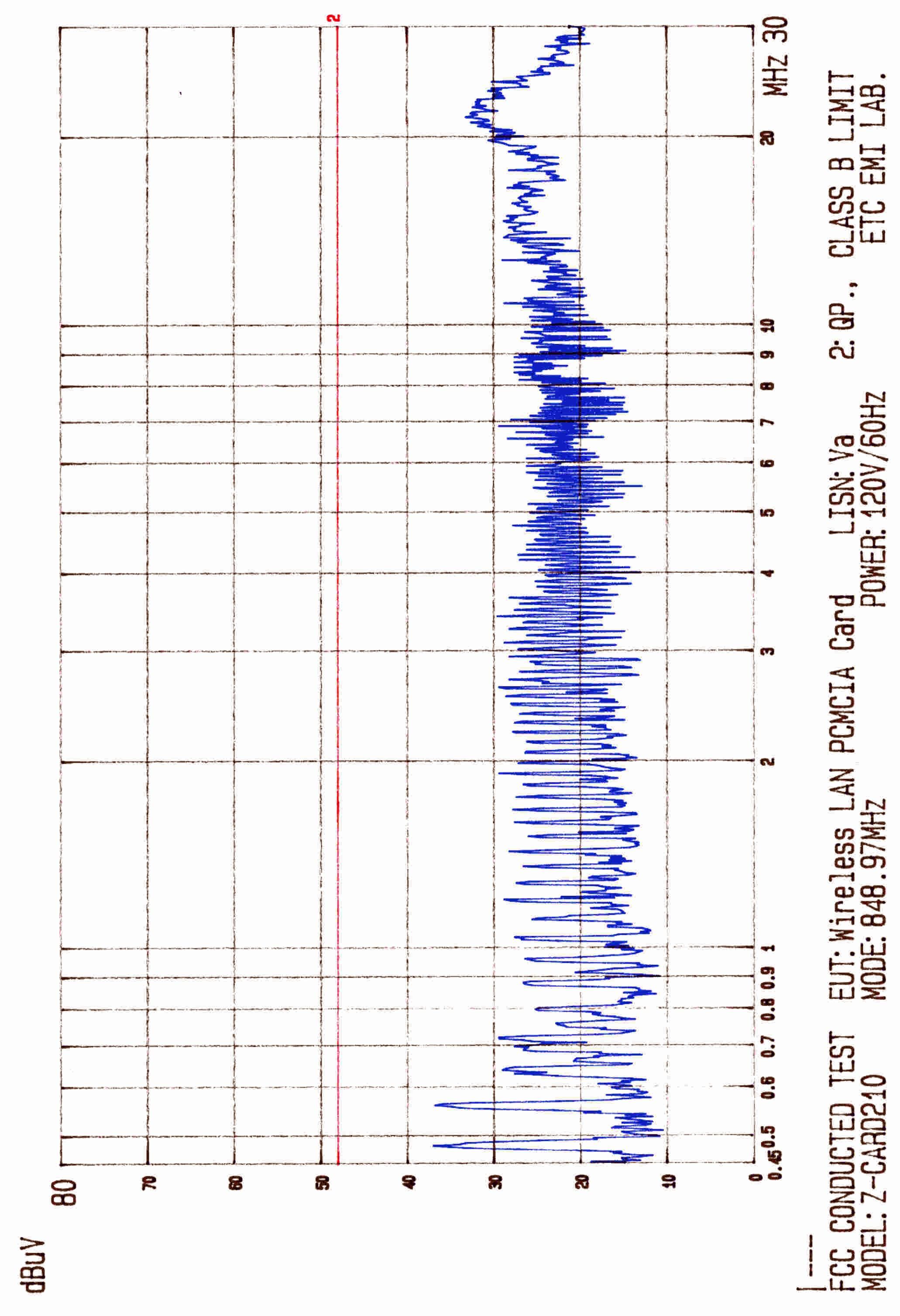
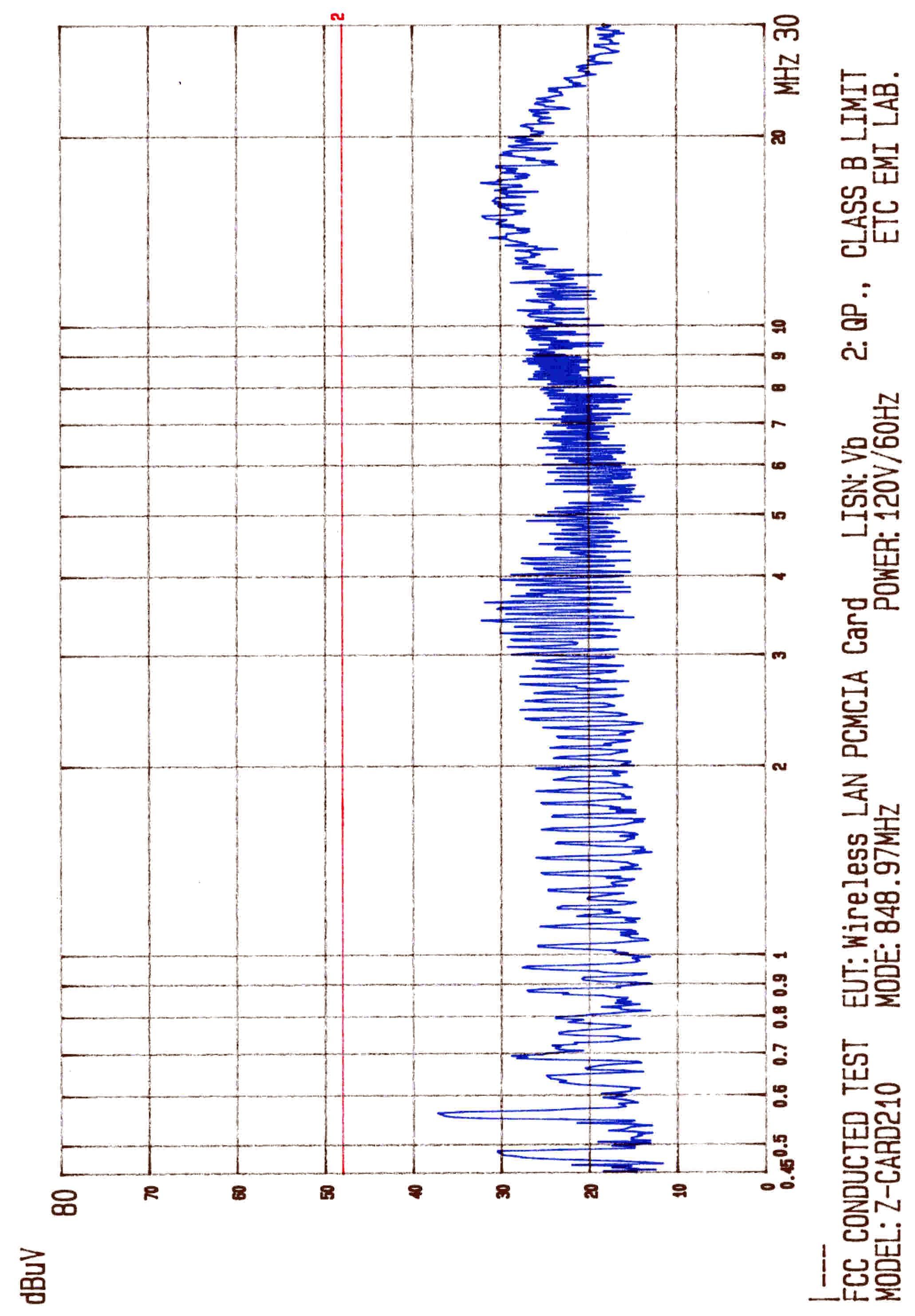
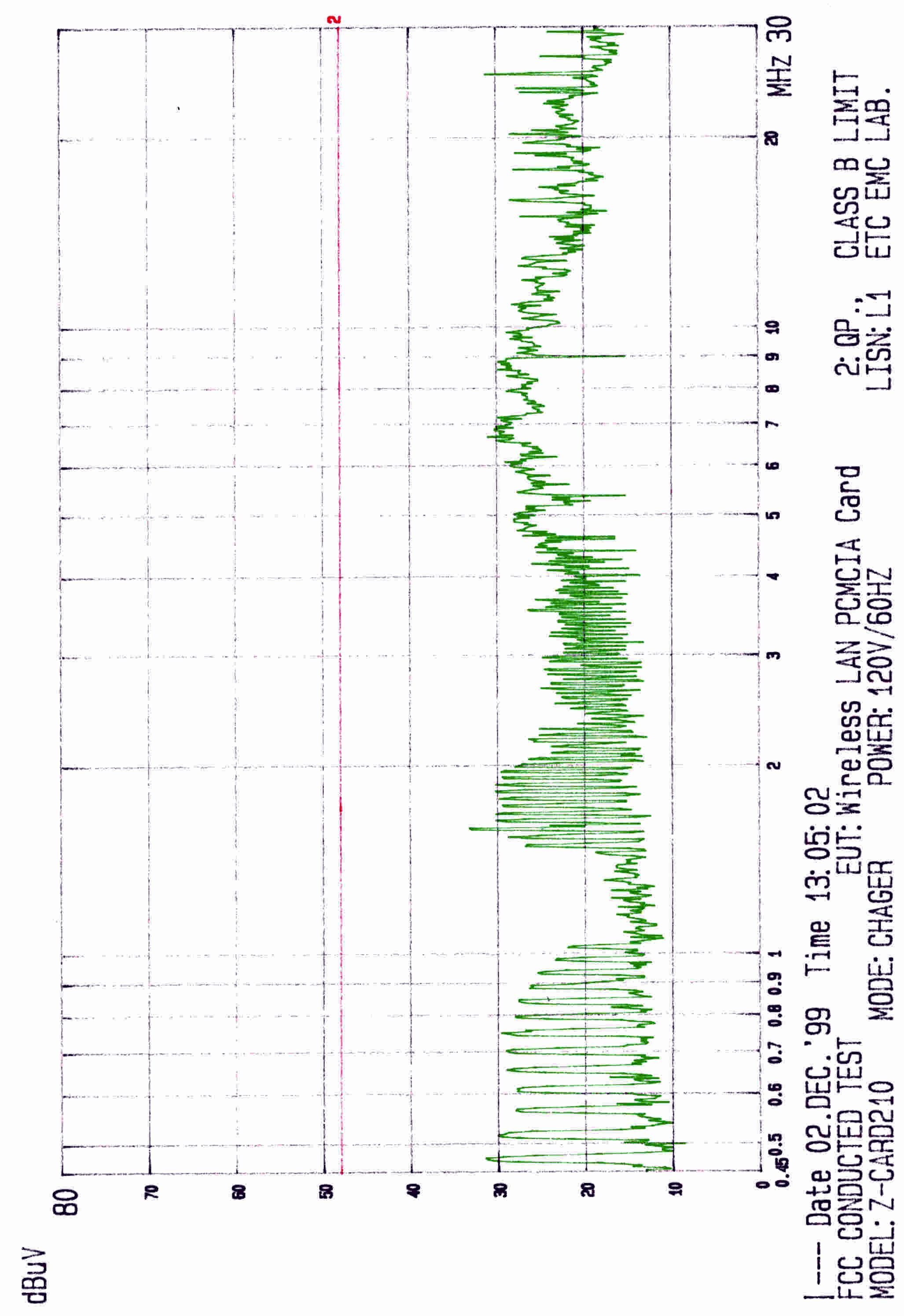
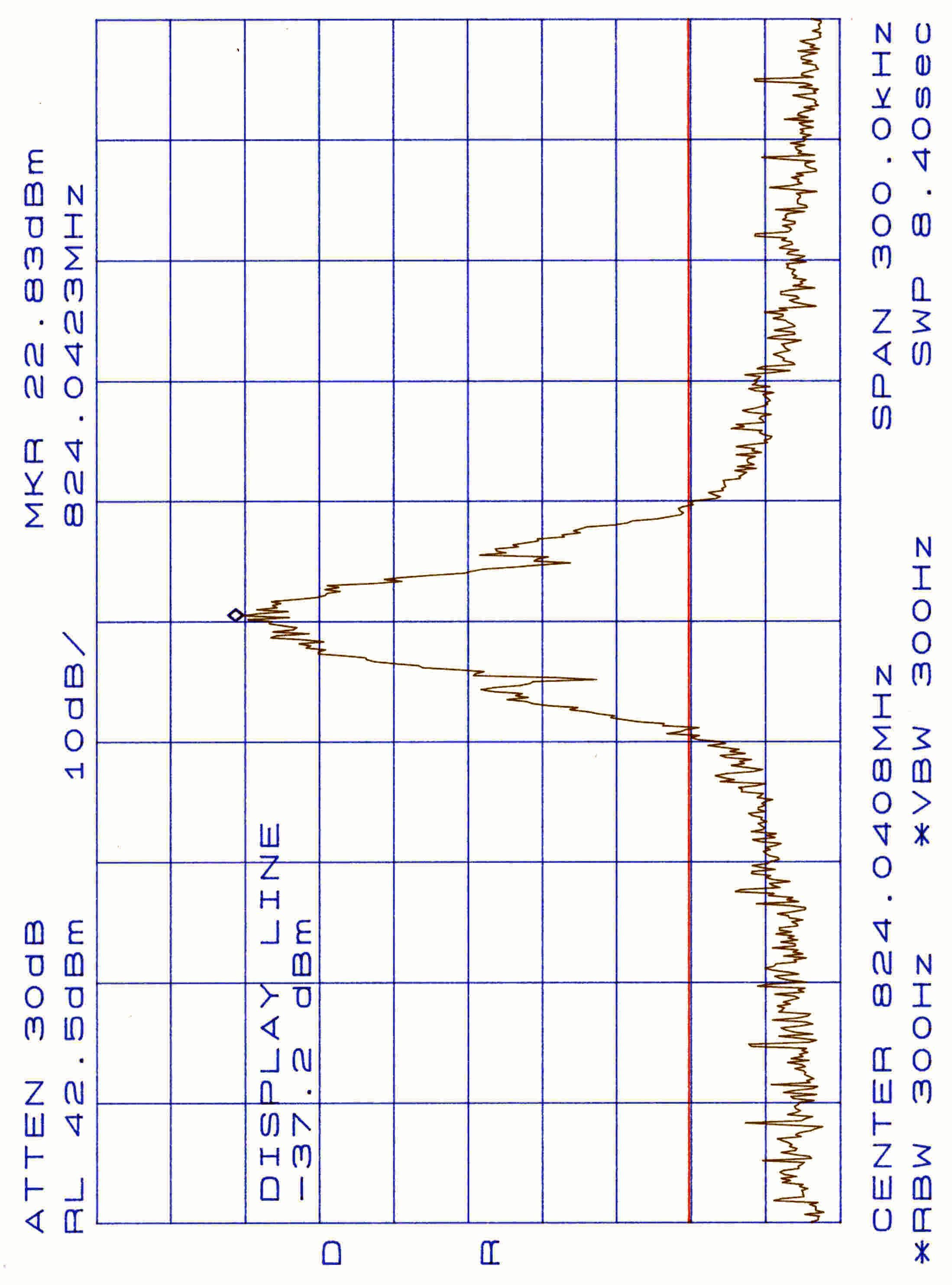
Document Text
Text extracted from the exhibit documents filed with the FCC. Open a document above to read the original.
Users Manual
01/04/12 C:\Ready_To_Convert\Doc\85217.DOC Quick Installation Guide for Z-Card 210 Here is a quick installation guide on what you need to know and do before using your Z-CARD 210. This guide also refers you to specific sections in the manual for further explanation. You will have to refer to some of these additional sections to know how to properly setup your Z- CARD 210. Step 1. You will need an IP address and the side preference from your CDPD Service Provider. a. You need a CDPD account for each Z-CARD 210. The carrier will provide an IP address for each account. You will need to give them the Z-CARD 210’s equipment ID (EID) which can be found on the label on top of the Z- CARD 210. The IP address is a valid Internet address and is matched up with your unique EID.= b. Side Preference: Does your Service Provider prefer A-side or B-side? Is there another CDPD Service Provider in your area? Usually you must give CDPD carrier the application area for the Z-CARD 210 to determine this setting. Step 2. Installing Z-Card CDPD Utilities for Windows 95 a. Insert the disk ”Z-Card CDPD Utilities for Windows 95 Disk #1“ into any 3 1/2 floppy drive. b. Click the Start button in the task bar and select the Run option. c. Type “A:\setup.exe”, and click OK or press Enter. d. Follow the instructions on the Setup screen and replace the disk ”Z-Card CDPD Utilities for Windows 95 Disk #2“ when required to. e. Wait for the Z-Card CDPD Utilities Setup window to appear, then click OK. 01/04/12 C:\Ready_To_Convert\Doc\85217.DOC f. In the next window, click the big button with a computer picture, and the Z-Card CDPD Utilities –Choose Program Group dialog box will appear. 01/04/12 C:\Ready_To_Convert\Doc\85217.DOC g. Choose Z-Card CDPD Utilities in the Program Group field. Then click Continue to complete the setup. h. Click OK to complete the setup program. i. Restart the computer. Step 3. Establish Hardware Connection To Setup your Z-CARD 210 a. With the Z-Card 210 modem’s label facing down, insert Z-Card 210 into your notebook’s PCMCIA slot. b. The Win95/98 will automatically detect the modem. A New Hardware Found message shows up. Step 4. Set up Dial-UP Network a. Double-click the My Computer icon on the desktop, then open Dial-Up Networking. 01/04/12 C:\Ready_To_Convert\Doc\85217.DOC b. Choose the Make New Connection icon and get into the dialog window. c. In the Make New Connection window, input the name of the connection and select Z-Card 210 CDPD Modem (in the type of the modem). Then select Next to view the next window. d. In this window you should input proper information of Area code, Telephone number, and country code. For example, if you're in Taiwan, you should input the area code with 002, the Telephone number with PPP, and the Country code with Taiwan, Republic of China (886). Then click Next to get into the next window. Z-Card 210 Z-Card 210 CDPD Modem 01/04/12 C:\Ready_To_Convert\Doc\85217.DOC e. Click Finish in the following window and Windows 95/98 will create an icon for your new connection. f. Select the icon of your new connection and choose the Properties item from the File function menu to open the next window. Z-Card 210 01/04/12 C:\Ready_To_Convert\Doc\85217.DOC g. In the General tab, uncheck Use country Code and Area Code. h. Go to Server Types. Select “Type of Dial-Up Server” with “SLIP: Unix Connection” and uncheck the “Log on to network”. Then click the “TCP/IP Settings” button. 01/04/12 C:\Ready_To_Convert\Doc\85217.DOC i. Select “Specify an IP Address” and then input the IP address provided by the service provider. Select “Specify name server addresses” and input IP addresses in the Primary DNS as well as Secondary DNS fields. Uncheck “Use IP Header Compression” and then click OK to finishing TCP/IP Setting. 01/04/12 C:\Ready_To_Convert\Doc\85217.DOC Step 5. To configure the Z-CARD 210 using AT commands a. To send AT Command to Z-Card 210, you must find a communications program to be operated in ASCII terminal emulation mode under your PCs (host). The followings are some typical programs: HYPER TERMINAL in WINDOWS 95 TELIX or similar alternatives In the Terminal Program you choose, set the parameters of the COM Port as follows: 19200 bps, 8 data bits, No parity check and 1 stop bit. b. AT Command for the Z-CARD 210 setup i. Set the IP Address AT!Ixxx.xxx.xxx.xxx , xxx.xxx.xxx.xxx is the IP Address e.g. AT!I203.67.40.233 ii. Set the Side Preference AT\N3 A Side Preference , AT\N4 B side Preference iii. Save all you setting into memory and Reset your Z-CARD 210 AT&W ATZ Step 6.Connecting to the CDPD Network a. Connecting to the CDPD network -- Run the TCP/IP stack Click My Computer, select Dial-Up Networking, and double-click Z-210. The Connect to dialog will appear. Click Connect to start the connection. Wait for the Terminal Screen dialog to appear, then click Continue to complete the connection. Step 7. Start Observer a. Click Start in the task bar, highlight Z-Card CDPD Utilities, and double-click Observer. i. Read the Observer status indicators. Definition of each indicator is described in more detail in the Z-Card 210 User’s Manual. ii. Open the Configuration Dialog, make sure that IP address and Channel Preference are set correctly. Either enable the Automatic Seek function or type the channel number of local area in the Manual Channel box. iii. Read the register and channel status indicators at Observer to ensure that your Z-Card 210 is registered to the CDPD network and has acquired an available channel, then start enjoying wireless Internet!
Attestation Statements
Z-Com, Inc. CDPD Z-Card 210 Statement of Compliance with Electronic Serial Number ESN Regulations The Electronic Serial Number ESN of Z-Com, Inc. Z-Card 210 is assigned to each device and set in the factory. The memory device where the ESN is stored is permanently solder to the main circuit board. CDPD SPECIFICATION 1.1 has strict regulation on ESN. Z-Com, Inc. Z-Card 210 meets the ESN regulation of CDPD SPECIFICATION 1.1 .
Cover Letter(s)
1.1. 1.2. Z-Com, Inc. A Wireless Networking Company 1.3. 7F-2, No.9, Prosperity 1st Rd., Science-Based Industrial Park, Hsinchu, Taiwan 1.4. Tel : 886-3-5777364 1.5. Fax : 886-3-5773359 Pnt@2000/2/4 Fcc_auth.doc 1/1 Z-Com, Inc. 7F-2, No.9, Prosperity 1st Rd., Science-Based Industrial Park, Hsinchu, Taiwan Tel : 886-3-5777364 Fax : 886-3-5773359 Federal Communications Commission Dear Sir: We, the undersigned, hereby authorize ELECTRONICS TESTING CENTER, TAIWAN & SPECTRUM RESERACH & TESTING LAB. to act on our behalf in all matters relating to application for AVL Terminal “Model: Z Card 210, ID No.: M4Y-ZCARD210 “ authorization, including the signing of all documents relating to these matters. Any and all acts carried out by ELECTRONICS TESTING CENTER, TAIWAN & SPECTRUM RESERACH & TESTING LAB. on our behalf shall have the same effect as acts of our own. The applicant certifies that in the case of an individual applicant (e.g., corporation), no party to the applicant is subject to a denial of federal benefits, that includes FCC benefits, pursuant to section 5301 of Anti-Drug abuse Act of 1988, 21 U.S.C. 862. For a definition of a “party” for these purposes see 47 C.F.R. 1.2002(b). By: By: Ms. Pi Chun, Hsu Title : Section Manager Applicant : Z-Com, Inc. Address : 7F-2, No.9, Prosperity 1st Rd., Science-Based Industrial Park, Hsinchu, Taiwan Tel : 886-3-5777364 ext.356 Fax: 886-3-5773359 Date : 9-DEC-99
ID Label/Location Info
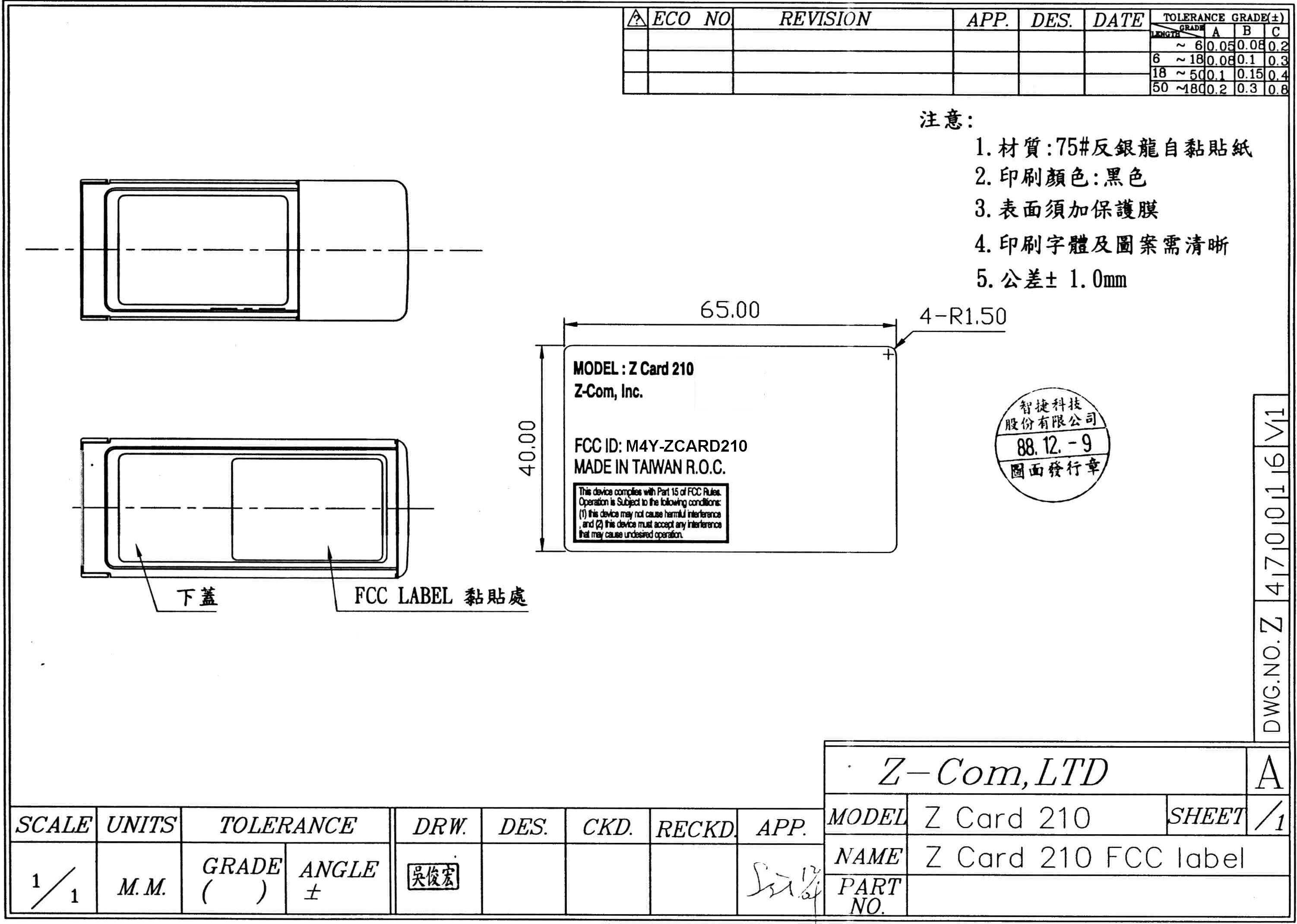
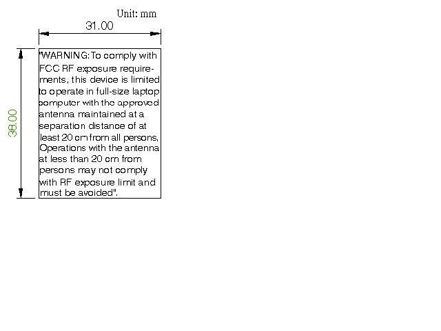
65.00 40.00 4-R1.50
Operational Description
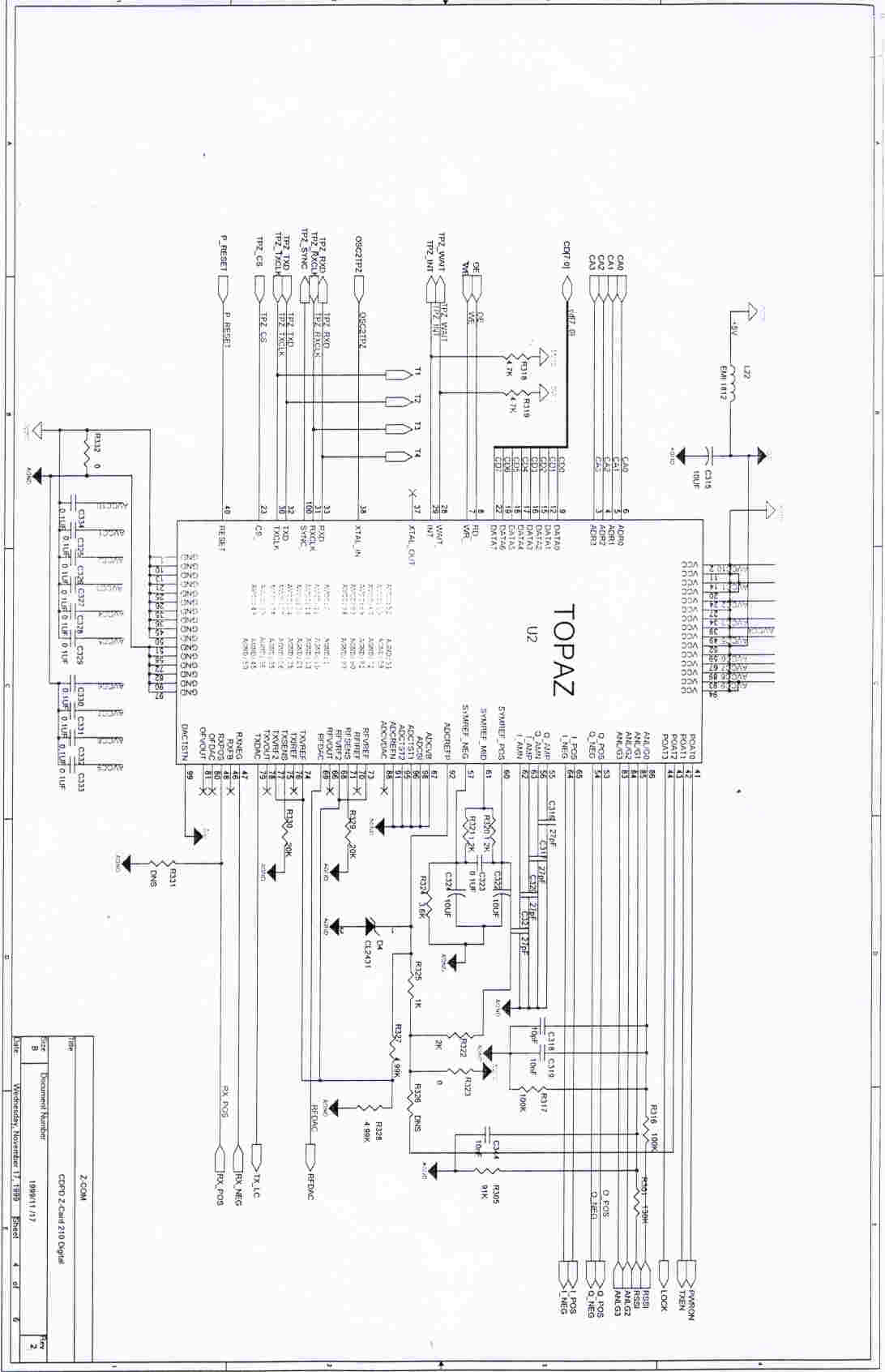
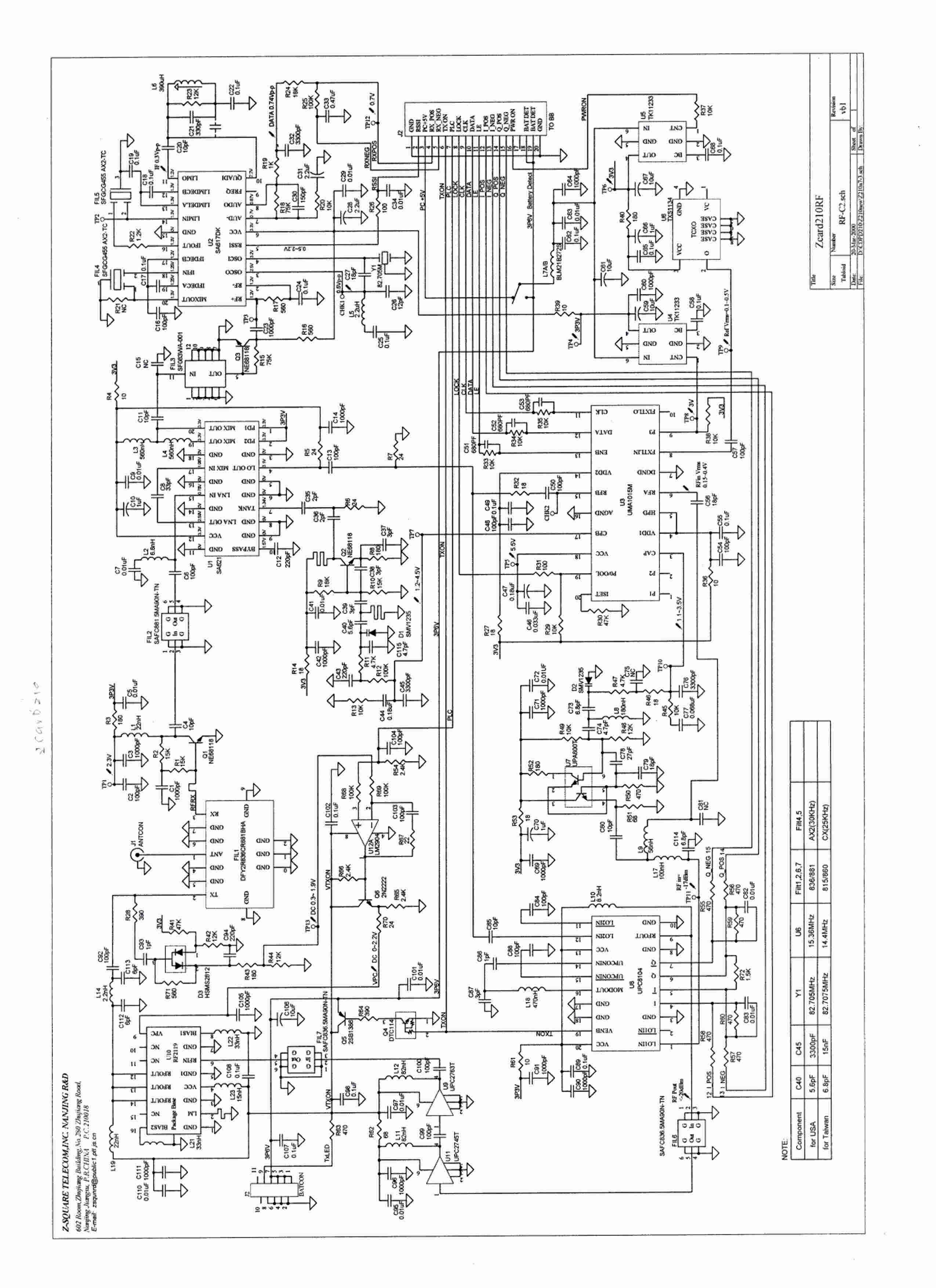
Z Square Telecom, Inc. Z210Theory.doc 1 Z-Card 210 Theory of operation 1.0 December 22,1999 Z Square Telecom, Inc. Z210Theory.doc 2 Table of Contents 1.0 PURPOSE 2.0 INTRODUCTION 3.0 RADIO THEORY OF OPERATION 3.1 RECEIVER OPERATION 3.2 TRANSMITTER OPERATION Z Square Telecom, Inc. Z210Theory.doc 3 1.0 Purpose The purpose of this document is to provide a detailed description of the circuitry that makes up Z SQUARE’S product 2.0 Introduction Appendix A presents the block diagram of Z SQUARE’S radio. The radio transceiver provides full-duplex operation with a transmitter architecture employing vector modulation of an offset loop oscillator and a receiver utilizing a dual-conversion, heterodyne architecture. The radio is designed to meet the CDPD specifications and comply with FCC regulations. The radio is controlled by the Ruby II. Communication Processor. It also passes signals to and from the Topaz radio interface IC, and transmits and receives radio signals between the MDBS over the airlink interface. The Z SQUARE’S Radio provides vector controlled modulation. The radio interface has a radio On/Off Control which is controlled by the Topaz CDPD Radio Interface Chip Port registers. It will control the power to the receiver chain and transmitter chain independently. The radio TX Power is controlled by the Topaz CDPD Radio Interface Chip TX Power D/A. The Ruby II Serial Controller is used to control the radio channel select synthesizers with configuration and synthesizer commands. 3.0 Radio Theory of Operation 3.1 Receiver Operation The receiver architecture of the radio is a typical double conversion super-heterodyne receiver. The block diagram of the receiver architecture is presented in Appendix A. It is also beneficial to relate the following information to the schematic diagram presented in appendix A. The power supply to the receiver chain is controlled with the PWRON line. A high voltage(>3.0V) enables the RF front end, the IF down converter /demodulator IC, the dual PLL IC, the TCXO, both the 1 st LO and 2 nd LO (128.16 MHz discrete design), and the voltage regulator which maintains voltage stability to the oscillators. A low voltage(<0.5V) to the PWRON line disables the power supply to the circuitry mentioned above. Z Square Telecom, Inc. Z210Theory.doc 4 In the receive path an antenna is connected to the duplexer which filters out the receive band between 869 and 894 MHz. The duplexer provides 50 dB isolation between the transmit and receive frequencies. The duplexer is followed by a low noise amplifier and a mixer IC. Between the LNA and mixer is an image reject filter. The 1st LO ranges in frequency from 952.20-977.13 MHz in 30KHz steps and is used to drive the mixer that downconverts the received signal to a first . IF frequency of 83.16 MHz(IF1,). The input level to the mixer is at -9 dBm +3 dB. This LO is generated by phase locking a voltage controlled oscillator to a temperature compensated crystal oscillator with the dual PLL IC. This ensures the accuracy of the down converted signal to be within +2.5 PPM (over temperature and voltage variation )of the 1st LO frequency. The inaccuracy of the second LO is insignificant since it is oscillating at a much lower frequency. The accuracy of the 1st LO is important with respect to the transmitted signal since this same LO is used to generate the transmit signal also. Following the 83.16 MHz IF filter is a high performance monolithic low-power FM IF system incorporating a mixer/oscillator, two limiting intermediate frequency amplifiers, a quadrature detector, a logarithmic received signal strength indicator(RSSI) with fast rise and fall time, and a voltage regulator receives the 83.16 MHz signal, down converts it to 455 KHz, amplifies it into limiting to strip off any AM components and then demodulates the remaining FM signal . The signal is taken off chip for two stages of IF filtering by two 455 KHz CERAMIC FILTERS WITH 30 KHz of bandwidth. U2 also generates the RSSI voltage. The demodulated output can be used as either a single ended or differential signal depending on assembly procedures. In the single ended mode the demodulated signal is present on RXPOS and the OFFDAC signal is looped back on the RXNEG connector pin so that the OFFDAC signal is used as the comparator voltage for the received data. In the differential mode the received data is present on both the RXPOS and RXNEG connector pins 180 o out of phase. In this configuration the OFFDAC line is used to control the center frequency of the demodulator tank circuit so that voltage offsets between the differential receive signals can be eliminated. 3.2 Transmitter Operation The transmitted signal from the radio is generated by mixing a low frequency vector modulated signal(2 nd LO)at 128.16 MHz with the 1 ST LO. The 1 st LO is the same one described in the receiver discussion above. The 1 ST LO has it’s power divided in two so that 1/2 the power can Z Square Telecom, Inc. Z210Theory.doc 5 be used to generate the transmitted signal. Both the 128.16 MHz signal and the 1 ST LO are phase locked to the TCXO(U6). A copy of the data sheet for the TCXO can be found in appendix A. Phase locking to the TCXO ensures that the output frequencies of the two PLL’s are accurate to within + 2.5 ppm of their respective frequencies and hence the transmitted signal is within +2.5 pm of its intended frequency over both temperature and voltage variations. The block diagram of the transmitter chain is presented in Appendix A. (The 128.16 MHz 2 nd LO is derived from a VCO circuit locked by 15.36MHz TCXO. It drives the Quadrature Modulator (U8). Inside the Modulator, the 2 nd LO is first multiplied by 2 to get 256.32MHz, then divided by 2 to obtain 0° and 90° orthogonal quaternary signals. Hese signals are modulated by I & Q signals respectively as shown in figure. The I & Q are 19.2Kbps signals generated by D/A converter according to MSK characteristics and GMSK filter (BT=0.5). The modulation inde…
Text truncated - open the document above for the full version.
Parts List/Tune Up Info
Z Com, Inc. 852321 Z-Card 210 Radio Part Factory Tune-up Procedure 1.0 December 22,1999 Z Com, Inc. 852322 Table of Contents 1.0 PURPOSE 2.0 SCOPE 3.0 RELATED DOCUMENTS 4.0 OVERVIEW 4.1 Introduction 4.2 Z-Card 210 Radio Reference Solution Architecture 5.0 FACTORY TUNE-UP PROCEDUES 5.1 TESTEQUIPMENT REQUTREMENT 5.2.1 INTRODUCTION 5.2.2 PROCEDURE 5.3 TUNING PROCEDURE 5.3.1 INTRODUCTION 5.3.2 PROCEDURE 6.0 Z-Card 210 RADIO PART DATA SHEET Z Com, Inc. 852323 1.0 Purpose The purpose of this document is to provide the necessary information to allow a test person to tune-up a Z-Card 210 Radio part in conjunction with the baseband card. 2.0 Scope This document will provide a top level description of the Z-Card 210 Radio Part. For the purposes of this factory tune-up procedure it will be assumed that the Z-Card 210 radio part is used with baseband card. . 3.0 Related Documents There are a number of related documents which are helpful when using this manual. They include the following a) Z-Card 210 CDPD User’s Manual b) Topaz CDPD Radio Interface Chip Data Sheet c) CDPD System Specification, Book III d) Z-Card 210 Radio Circuitry Description 1.0 The Z-Card 210 CDPD User’s Manual provides the necessary information to operate a CDPD-MES modem. The Topaz CDPD Radio Interface Chip Data Sheet provides same type of information for the Topaz CDPD Radio Interface. Book III of the CDPD System Specification provides the detailed requirements of the CDPD network system. The Z-Card 210 Radio Circuitry Description 1.0 provides information on the circuits relevant to FCC part 22 certification. 4.0 Overview 4.1 Introduction Figure 4-1 shows the elements of the CDPD network. This network provides packetized data communications over the same channels used by the AMPS cellular voice system. It does this by using unused channels or channels dedicated to CDPD. See the CDPD Specification for more information. The primary components are the MES (Mobile End System) the MDBS(Mobile Data Base Station) and the MDIS(Mobile Data Intermediate System). The M-ES is the only mobile component of the CDPD network. It uses a radio to communicate over the airlink interface to a MDBS. As the MES roams, hand-offs will occur between MDBSs. Z Com, Inc. 852324 Figure 4-1 CDPD Network The MES communicates to both the MDBS and the MDIS but at different layers of the CDPD protocol. The MDIS is also connected to a wired backbone which can provide internet access, transportation to a corporate LAN, or another M-ES(with the help of another MDBS) Z-Card 210 is a CDPD MES which will operate in such a CDPD network environment. Z Com, Inc. 852325 4.2 Z-Card 210 Radio Part Circuit Architecture The Z-Card 210 radio part is the MES’ transceiver portion of the CDPD Network. Figure 4-2 presents the block diagram of Z-Card 210 radio. Figure 4-2 Z-Card 210 Radio Block Diagram The radio transceiver provides full-duplex operation with a transmitter architecture employing vector modulation of an offset loop oscillator and a receiver utilizing a dual-conversion, heterodyne architecture. The radio is designed to meet CDPD specifications and to be FCC compliant . Within the context of the Z-Card 210 CDPD Reference Solution, the radio is controlled by the Ruby II Communications Processor. It also passes the signals to and from the Topaz radio interface IC, and transmits and receives radio signals to and from the MDBS over the airlink interface . For further information see the Ruby II Communications Processor and Topaz CDPD Radio Interface IC Data Sheets. The Z-Card 210 Radio part interface is shown in Figure 4-3 . The Z-Card 210 Radio provides vector controlled modulation. The Z-Card 210 radio interface has a radio On/Off Control which is controlled by the Topaz CDPD Radio Interface Chip Port registers. The Z-Card 210 radio TX Power is controlled by the Topaz CDPD Radio Interface Chip TX Power D/A . Z Com, Inc. 852326 A micro controller (Ruby )which resides in Z-Card 210 baseband PCMCIA card is used to control the Z-Card 210 radio channel select synthesizers with configuration and synthesizer commands. Data Exchange Interface Port0 Port1 Radio On/Off Control TXDis RXDis Topaz Radio RX Bit Oetector/ Demod Offset TX Symbol Generator TX Power D/A RSSI A/D Demodulator Modulator TX Power Control Signal Level Detector RXPos RXNeg OffDA Q Pos Q Neg I Pos INeg TXDAC ANLOG0 RXPos RXNeg OffDAC RSSI Q Pos Q Neg I Pos INeg TXDAC Serial Controller Ruby TX/RX Synthesizer Control Ground Data Exchange Interface SRL C1 SRLC0 SRL C2 GND Clock Enable Data GND Figure 4-3 Z-Card 210 Radio Interface Z Com, Inc. 852327 5.0 Factory Tune-up procedures All data taken should be recorded on a copy of sample data sheet in section 6. 5.1 Test Equipment Requirements The following test equipment(or equivalents) are required to properly tune the Z- Card 210 Radio. 1. Tested Z-Card 210 baseband assembly with baseband/radio interface cable. 2. Personal computer with the RFTEST test software and PCMCIA prot. 3. HP E3610A DC power supply. 4. HP.8595E spectrum analyzer. 5. HP 8643A synthesized signal generator 6. HP 53131A universal counter w/option 010 high stability oven. 7. Fluke 87 RMS multimeter. 8. SMA compatible 10 dB 50 resistive attenuator. 9. Tektronix TDS 540A 4 channel digitizing oscilloscope. 5.2 Pre-tuning procedure 5.2.1 Introduction This section describes the steps to take before the actual alignment of the radio should begin. The effort in this section is to visually inspect the assembled radio and measure the resistance between the three power supply positions and ground, and power on the radio to ensure proper power consumption. 5.2.2 1. Visually inspect the radio to verify all components have been installed. 2. Measure the resistance between the +3.6V supply input on J2 pin 1,3,5,7 and ground(pin 2,4,6,8). Resistance J2, 1, 3,5,7 to GND OHM typically 2M OHM 3.Measure the resistance between synthesizers power and ground. OHM Resistance U5_4 to GND typically = 1.9K OHM 4.Measur…
Text truncated - open the document above for the full version.
RF Exposure Info
FCC ID.: M4Y-ZCARD210 Rev. No 1.0 RF Maximum Permissible Exposure Measurement Report of E.U.T. : CDPD Transceiver MODEL : Z CARD 210 FCC ID. : M4Y-ZCARD210 for APPLICANT: Z-COM, INC. ADDRESS: 7F-2, NO. 9, PROSPERITY 1ST RD., SCIENCE-BASED INDUSTRIAL PARK, HSINCHU, TAIWAN, R.O.C. Test Performed by ELECTRONICS TESTING CENTER, TAIWAN NO. 8 LANE 29, WENMIMG ROAD, LOSHAN TSUN, KWEISHAN HSIANG, TAOYUAN, TAIWAN, R.O.C. Tel:(03)3280026-32 Fax:(03)3280034 Report Number : ET88R-10-032 ETC Report No. : ET88R-10-032 FCC ID.: M4Y-ZCARD210 Rev. No 1.0 TEST REPORT CERTIFICATION Applicant: Z-COM, INC. 7F-2, NO. 9, PROSPERITY 1ST RD., SCIENCE-BASED INDUSTRIAL PARK, HSINCHU, TAIWAN, R.O.C. Manufacturer: Z-COM, INC. 7F-2, NO. 9, PROSPERITY 1ST RD., SCIENCE-BASED INDUSTRIAL PARK, HSINCHU, TAIWAN, R.O.C. Description of EUT: a) Type of EUT: CDPD Transceiver b) Model No.: Z CARD 210 c) FCC ID. : M4Y-ZCARD210 d) Power Supply: DC 5V Regulation Applied: IEEE C95.1-1991, FCC 47 CFR Part 1 and Part 2 I HEREBY CERTIFY THAT: The data shown in this report were made in accordance with the procedures given in IEEE C95.1, and the energy emitted by the device was founded to be within the limits applicable. I assume full responsibility for accuracy and completeness of these data. Note: 1. The result of the testing report relates only to the item tested. 2. The testing report shall not be reproduced expect in full, without the written approval of ETC. Issued Date :MAR. 29, 2000 Test Engineer : ( K. C. Chen ) Approve & Authorized Signer : Will Yauo, Supervisor EMI Test Site of ELECTRONICS TESTING CENTER, TAIWAN ETC Report No. : ET88R-10-032 FCC ID.: M4Y-ZCARD210 Rev. No 1.0 Table of ContentsPage 1 GENERAL INFORMATION ........................................................................................... 1 1.1Product Description ............................................................................................. 1 1.2Characteristics of Device..................................................................................... 1 1.3Test Methodology ................................................................................................ 1 1.4Test Facility......................................................................................................... 1 2 PROVISIONS APPLICABLE .......................................................................................... 2 2.1Definition ............................................................................................................. 2 2.2Relative Requirement for Compliance ................................................................ 2 3. SYSTEM TEST CONFIGURATION............................................................................... 3 3.1Justification .......................................................................................................... 3 3.2Devices for Tested System................................................................................... 3 4 M AXIMUM P ERMISSIBLE E XPOSURE M EASUREMENT ....................................................... 4 4.1Applicable Standard............................................................................................. 4 4.2Measurement Procedure ...................................................................................... 4 4.3Measurement Instrument ..................................................................................... 5 4.4Power Desity Data ............................................................................................... 5 A PPENDIX AS PECIFICATION OF D EVICE U NDER T EST ...................................................... 6 ETC Report No. : ET88R-10-032Page 1 of 6 Pages FCC ID.: M4Y-ZCARD210 1 GENERAL INFORMATION 1.1Product Description a) Type of EUT: Wireless LAN Card b) Trade Name: Z-Com c) Model No.: Z CARD 210 d) Power Supply: DC 5V 1.2Characteristics of Device This device is a CDPD wireless modem and its maximum rated output peak power is 0.6W. this device uses GMSK modulation for wireless transmission. It is for data transmission only, no audio or voice signal operation is avaible. This device also meets the CDPD wireless standards Ver. 1.0 and 1.1 and supports UDC/TCP communication protocol for accessing the Internet and CDPD network. 1.3Test Methodology The Maximum Permissible Exposure (MPE) was performed according to the procedures illustrated in IEEE C95.1-1991. 1.4Test Facility The open area test site and conducted measurement facility used to collect the radiated data is located on the roof top of Building at No.34, 5 Lirn, Din Fu Tsun, Lin Kou, Taipei, Taiwan, R.O.C. This site has been fully described in a report submitted to the FCC, and accepted in a letter dated Feb. 10, 1997. ETC Report No. : ET88R-10-032Page 2 of 6 Pages FCC ID.: M4Y-ZCARD210 2 PROVISIONS APPLICABLE 2.1Definition MPE in Occupational / Controlled Environments: Persons are exposed as a consequence of their employment provided those persons are fully aware of the potential for exposure and can exercise control over their exposure. Also apply to a individual is transient through a location where occupational / controlled limits apply provided he or she is made aware of the potatial for exposure. MPE in General Population / Uncontrolled Environments: General population / Uncontrilled exposure apply in situation in which the general public may be exposed, or in which persons that are exposed as a consequence of their employment nay not be fully aware of the potatial for exposure or cannot execise control over their exposure. 2.2Relative Requirement for Compliance (1) MPE for Controlled Enviroments According to section 1.1310 of FCC 47 CFR Part 1, MPE Limits for controlled enviroment are as following: Frequency Range (MHz) Electric Field Strength (V/m) Magnetic Field Strength (A/m) Power Density (mW/cm 2 ) Averaging Time (minutes) 0.3-3.06141.63*1006 3-301842/f4.89/f*900/f 2 6 30-30061.40.1631.06 300-1500----------f/3006 1500-100,000----------5…
Text truncated - open the document above for the full version.
RF Exposure Info
Dear Sir, Sorry for the delay. The followings are for your requests: 1. Thanks for your instructions. The applicant will add the required information into user manual for RF safety requirement. The modified manual was also uploaded via FCC Web Site. Please kindly check it and thank you again. 2. We will follow your instructions to keep minimum file numbers. Wish you with the best, K. C. Chen ETC/EMC DEpartment
RF Exposure Info
00/05/05 D:\Ready_To_Convert\Doc\98977.DOC Quick Installation Guide for Z-Card 210 Here is a quick installation guide on what you need to know and do before using your Z-CARD 210. This guide also refers you to specific sections in the manual for further explanation. You will have to refer to some of these additional sections to know how to properly setup your Z- CARD 210. Step 1. You will need an IP address and the side preference from your CDPD Service Provider. a. You need a CDPD account for each Z-CARD 210. The carrier will provide an IP address for each account. You will need to give them the Z-CARD 210’s equipment ID (EID) which can be found on the label on top of the Z- CARD 210. The IP address is a valid Internet address and is matched up with your unique EID. b. Side Preference: Does your Service Provider prefer A-side or B-side? Is there another CDPD Service Provider in your area? Usually you must give CDPD carrier the application area for the Z-CARD 210 to determine this setting. Step 2. Installing Z-Card CDPD Utilities for Windows 95 a. Insert the disk ” Z-Card CDPD Utilities for Windows 95 Disk “ into any 3 1/2 floppy drive. b. Click the Start button in the task bar and select the Run option. c. Type “ A:\setup.exe ”, and click OK or press Enter . d. Follow the instructions on the Setup screen e. Wait for the Start Coping Files window to appear, then click NEXT . 00/05/05 D:\Ready_To_Convert\Doc\98977.DOC f. Click OK to complete the setup program. g. Restart the computer. Step 3. Establish Hardware Connection To Setup your Z-CARD 210 a. With the Z-Card 210 modem’s label facing down, insert Z-Card 210 into your notebook’s PCMCIA slot. b. The Win95/98 will automatically detect the modem. A New Hardware Found message shows up. Step 4. Set up Dial-UP Network a. Double-click the My Computer icon on the desktop, then open Dial-Up Networking . 00/05/05 D:\Ready_To_Convert\Doc\98977.DOC b. Choose the Make New Connection icon and get into the dialog window. c. In the Make New Connection window, input the name of the connection and select Z-Card 210 CDPD Modem (in the type of the modem). Then select Next to view the next window. 00/05/05 D:\Ready_To_Convert\Doc\98977.DOC d. In this window you should input proper information of Area code, Telephone number, and country code. For example, if you're in Taiwan, you should input the area code with 002, the Telephone number with PPP, and the Country code with Taiwan, Republic of China (886). Then click Next to get into the next window. e. Click Finish in the following window and Windows 95/98 will create an icon for your new connection. 00/05/05 D:\Ready_To_Convert\Doc\98977.DOC f. Select the icon of your new connection and choose the Properties item from the File function menu to open the next window. g. In the General tab , uncheck Use country Code and Area Code . h. Go to Server Types . Select “ Type of Dial-Up Server ” with “ SLIP: Unix Connection ” and uncheck the “ Log on to network” . Then click the “ TCP/IP Settings ” button. 00/05/05 D:\Ready_To_Convert\Doc\98977.DOC i. Select “ Specify an IP Address ” and then input the IP address provided by the service provider. Select “ Specify name server addresses ” and input IP addresses in the Primary DNS as well as Secondary DNS fields. Uncheck “ Use IP Header Compression ” and then click OK to finishing TCP/IP Setting. 00/05/05 D:\Ready_To_Convert\Doc\98977.DOC Step 5. To configure the Z-CARD 210 using AT commands a. To send AT Command to Z-Card 210, you must find a communications program to be operated in ASCII terminal emulation mode under your PCs (host). The followings are some typical programs: HYPER TERMINAL in WINDOWS 95 TELIX or similar alternatives In the Terminal Program you choose, set the parameters of the COM Port as follows: 19200 bps, 8 data bits, No parity check and 1 stop bit. b. AT Command for the Z-CARD 210 setup i. Set the IP Address AT!Ixxx.xxx.xxx.xxx , xxx.xxx.xxx.xxx is the IP Address e.g. AT!I203.67.40.233 ii. Set the Side Preference AT\N3 A Side Preference , AT\N4 B side Preference iii. Save all you setting into memory and Reset your Z-CARD 210 AT&W ATZ Step 6…
Text truncated - open the document above for the full version.
Contact Information
Applicant
Jeff jiang(R&D DIV Director)
Technical Contact
ELECTRONICS TESTING CENTER, TAIWANK. C. CHEN
[email protected]886-2-26023052
NO. 34, LIN 5, DING FU TSUNG, LINKOU HSIANG · TAIPEI HSIEN · Taiwan
Non-Technical Contact
EK. C. CHEN
[email protected]886-2-26023052
Test Firm
Electronics Testing Center, TaiwanWill Yauo
Technical Specifications
| # | Rule Parts | Frequency Range | Power Output | Emission | Tolerance |
|---|---|---|---|---|---|
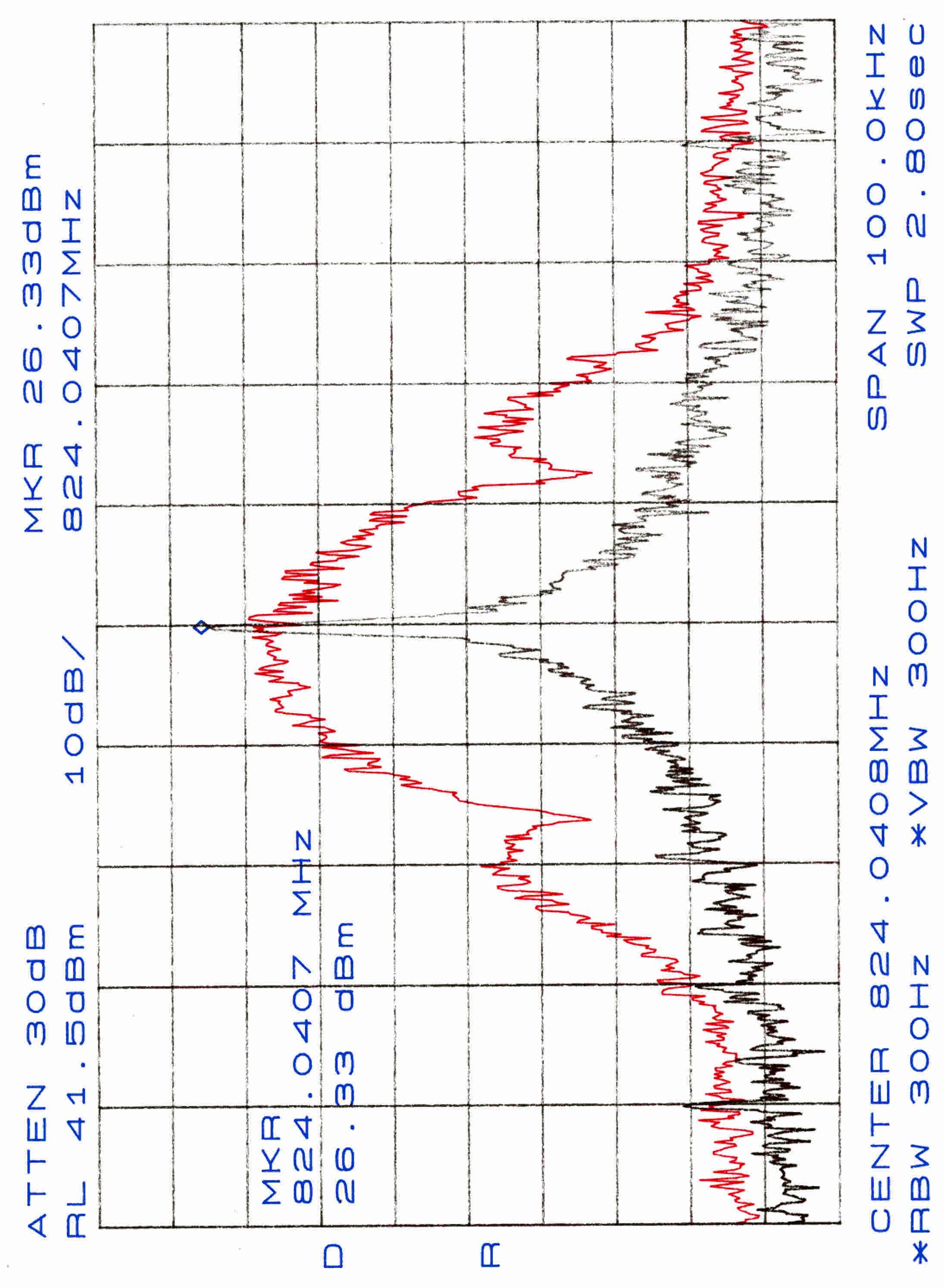
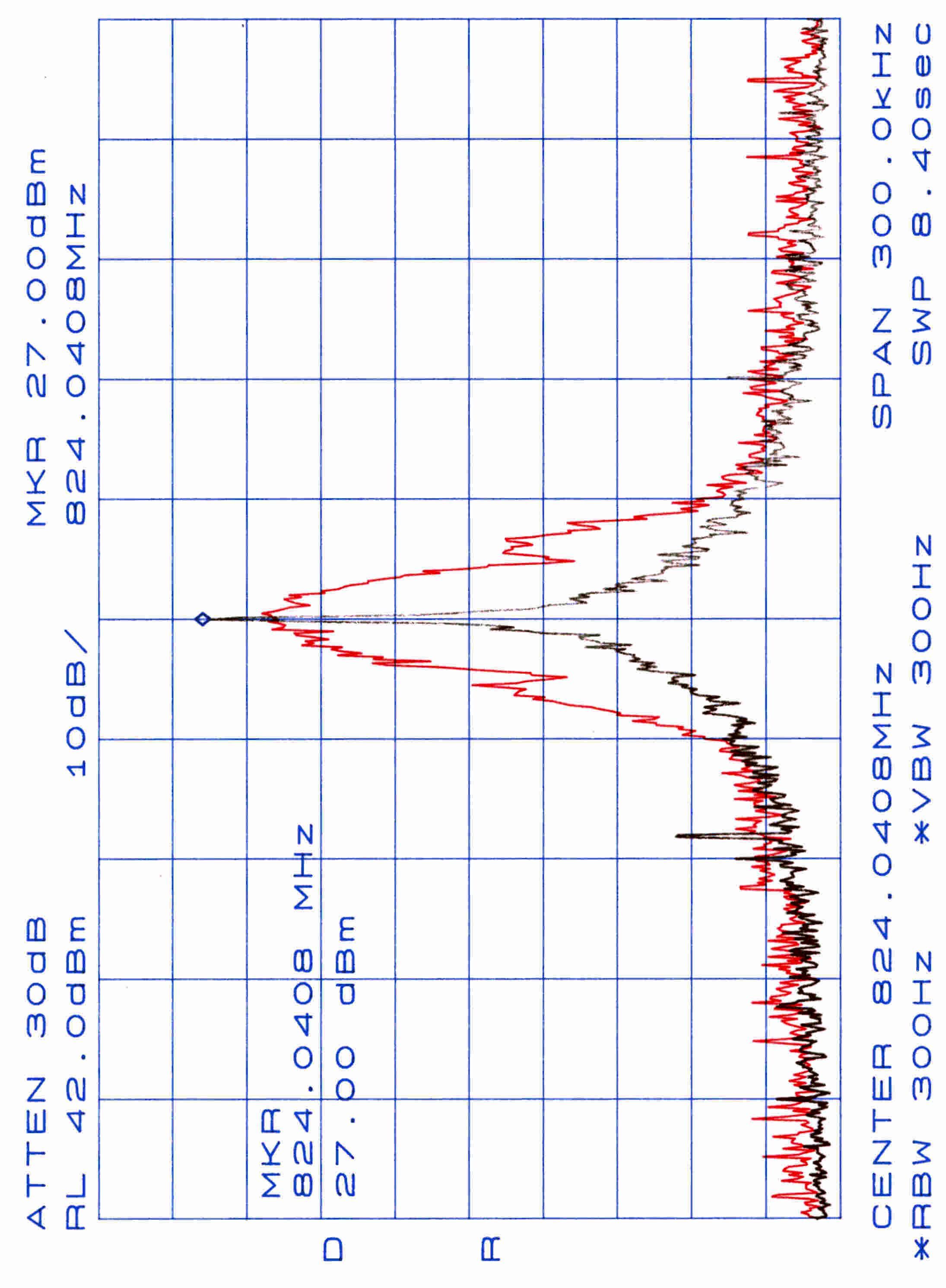
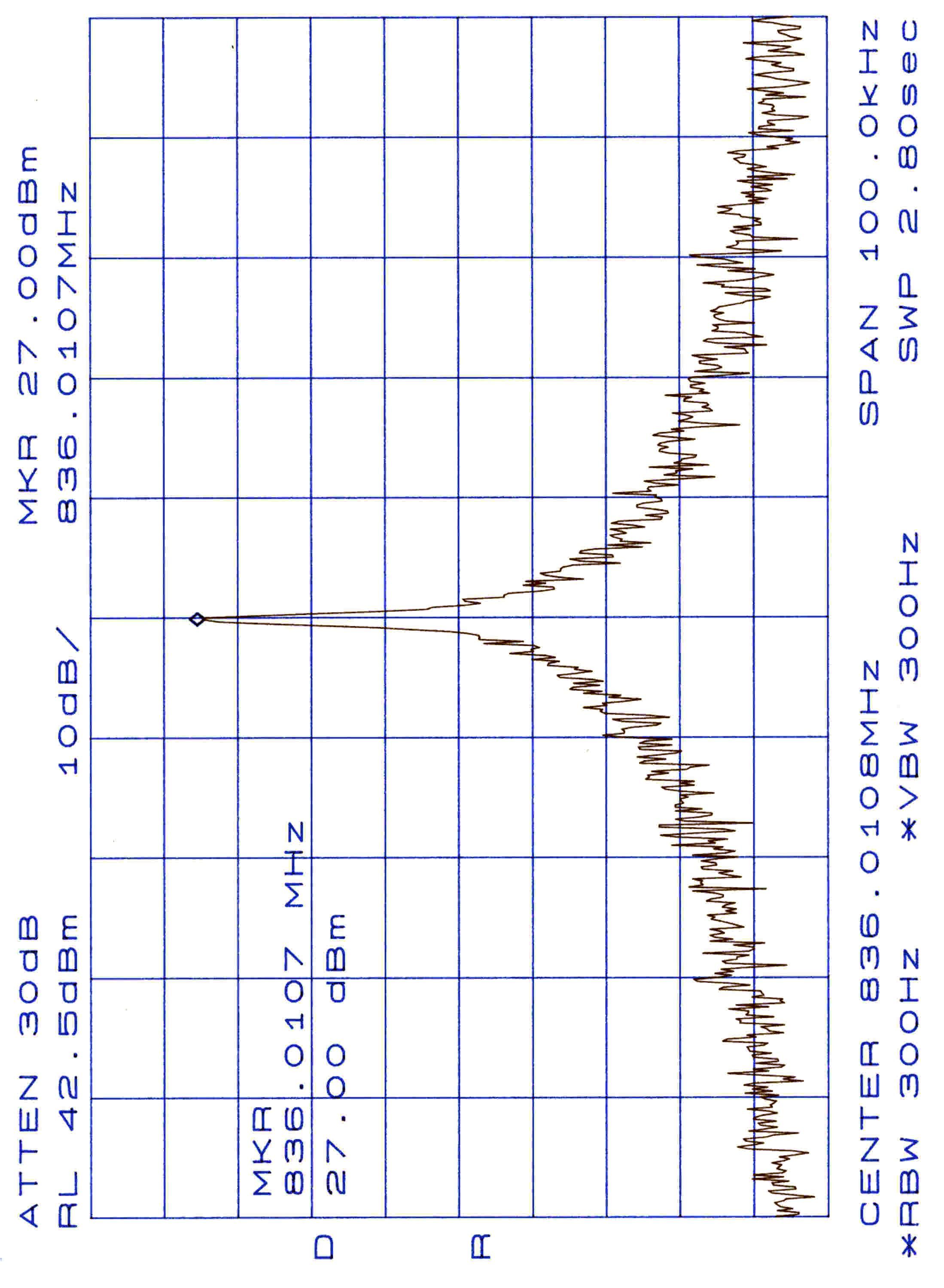
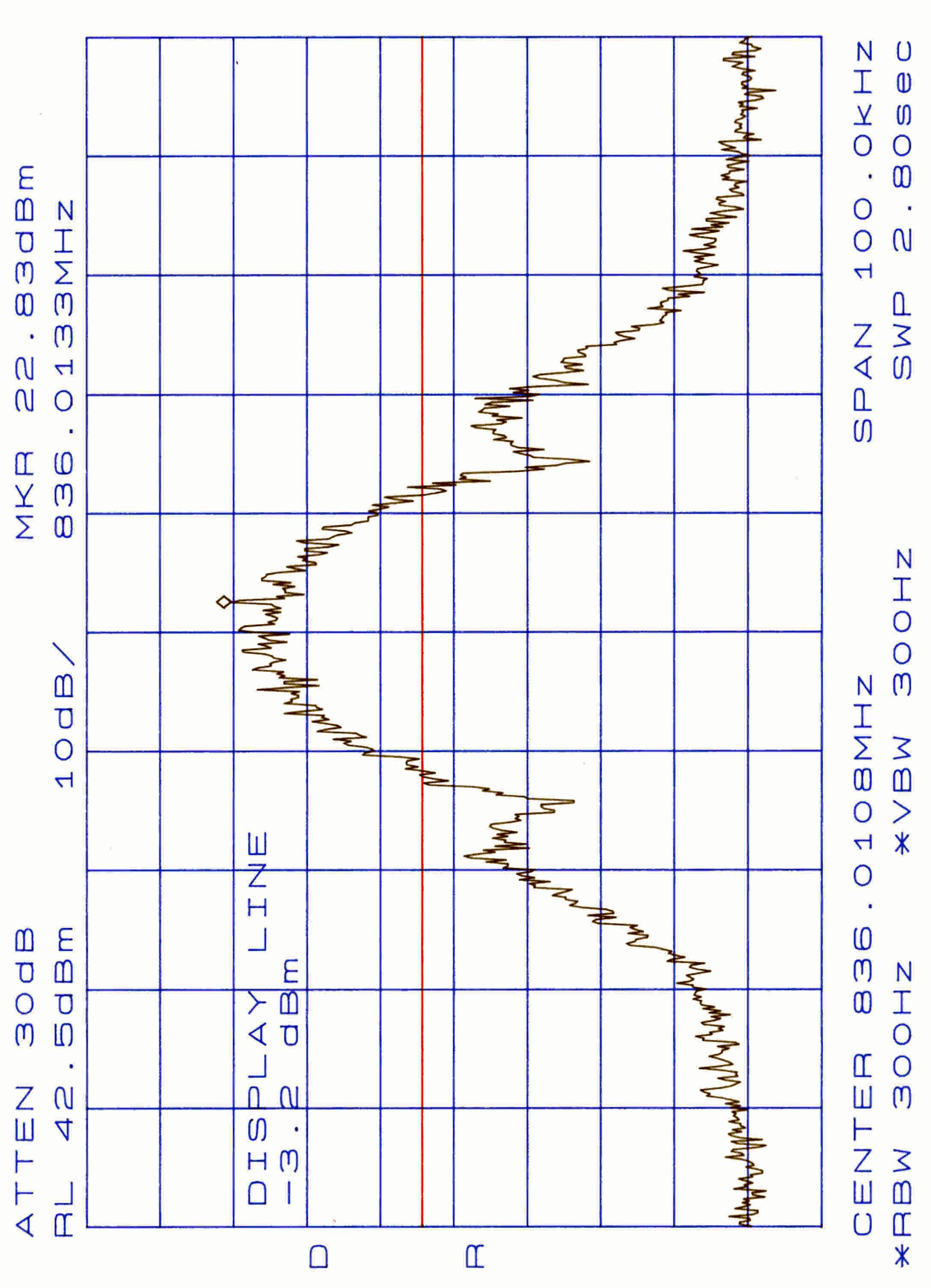
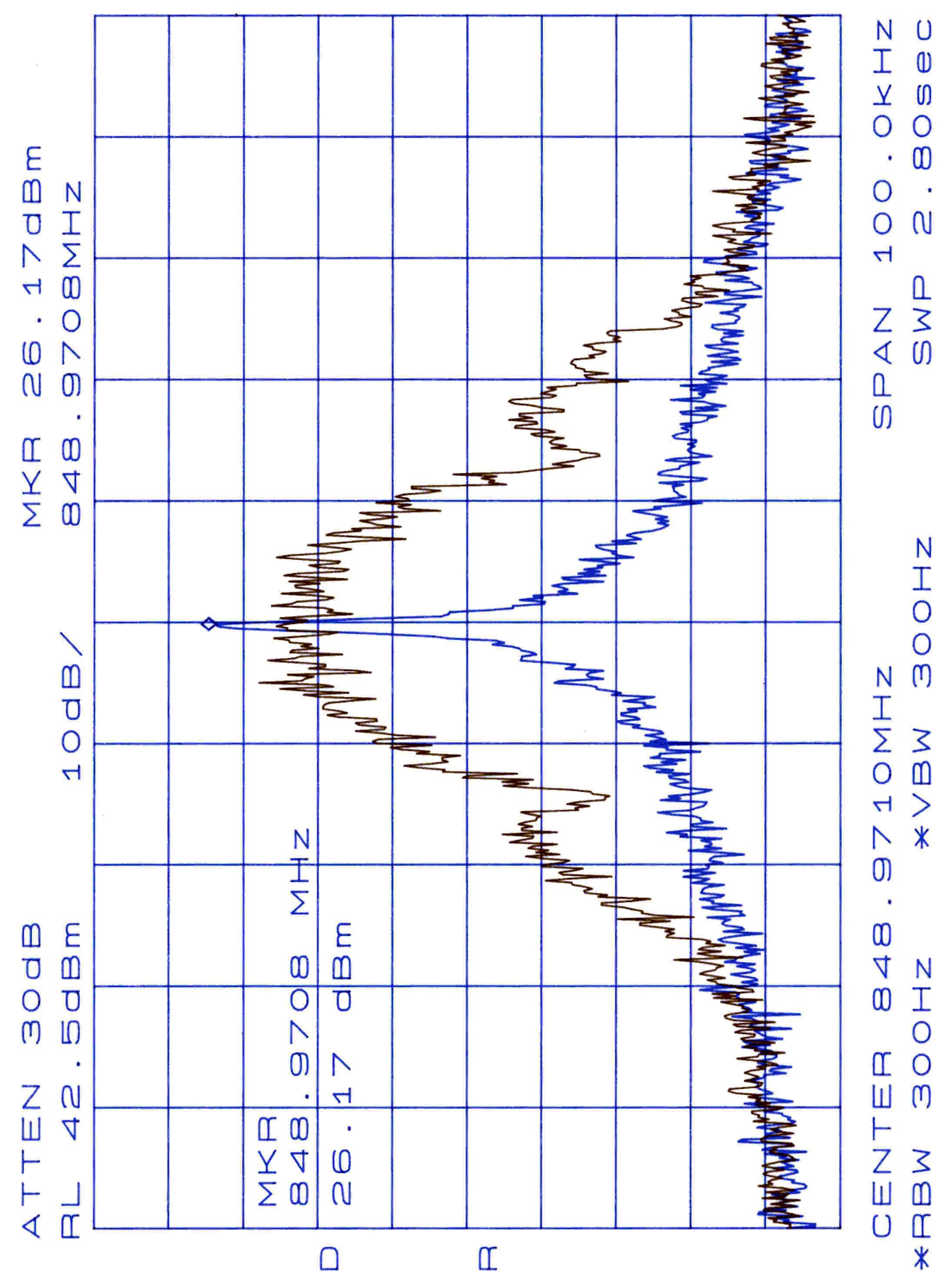
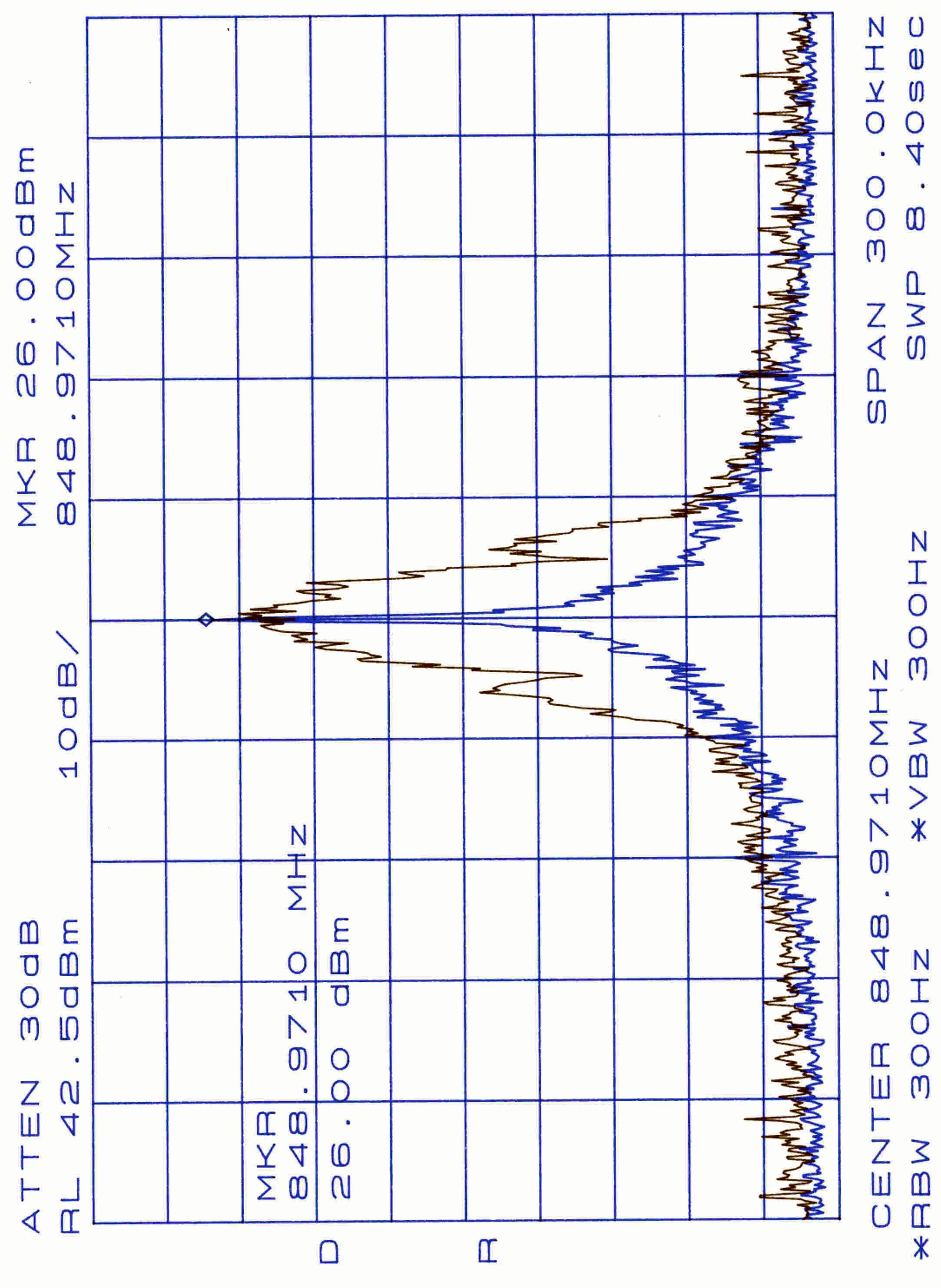
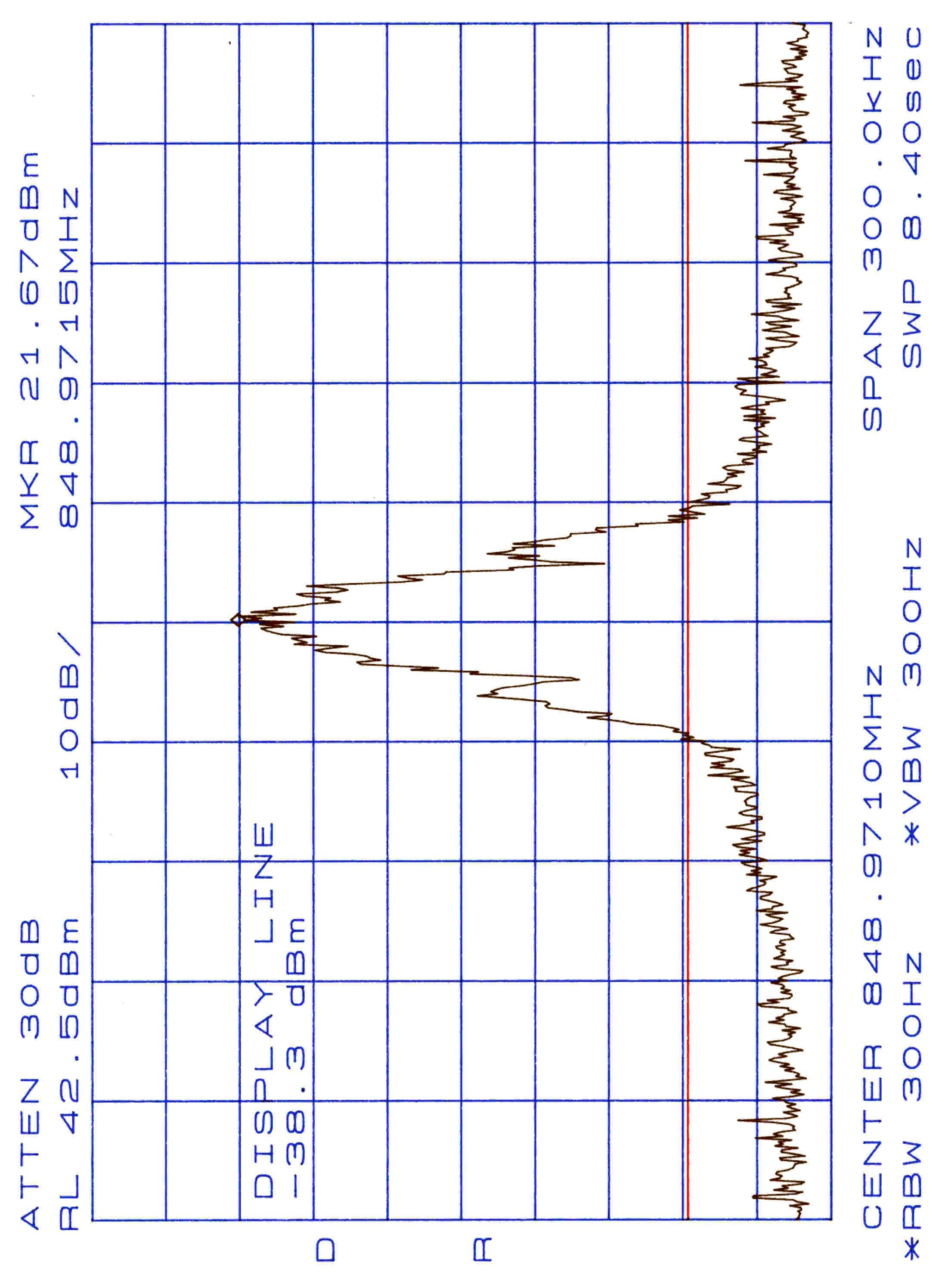
| 1 | 22.901(d) | 824.04 MHz - 848.97 MHz | 676.00 mW | 30K0G1D | 0.0002500000 % |
Other Applications from Z Com Inc
M4Y-AS240
Dec 13, 2022802.11ax Access Point
Equipment Class
DTS - Digital Transmission System
M4Y-AC720M
Aug 14, 2022802.11ac Wireless LAN USB Module
Equipment Class
NII - Unlicensed National Information Infrastructure TX
M4Y-SP230
Feb 21, 2021802.11 ac Wave 2 Access Point
Equipment Class
NII - Unlicensed National Information Infrastructure TX
M4Y-SP220C02
Jan 21, 2020802.11ac Access Point
Equipment Class
NII - Unlicensed National Information Infrastructure TX
M4Y-SP220C03
Jan 20, 20205GHz 11ac Wireless Bridge
Equipment Class
NII - Unlicensed National Information Infrastructure TX