M5VC19753UProx Reader Mifare (Teardrop)
Gallagher Group Ltd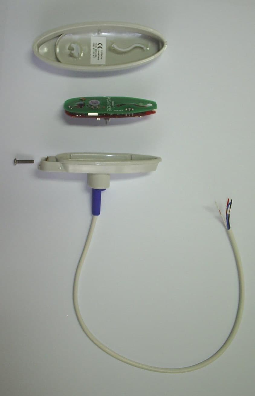
Click to zoom
Application Details
- Equipment Class
- DXT - Part 15 Low Power Transceiver, Rx Verified
- Date of Grant
- Aug 11, 2010
- Application Purpose
- Original Equipment
- Date of Application
- Aug 10, 2010
- Equipment Note
- Prox Reader Mifare (Teardrop)
- Frequency Range
- 13.56000000 - 13.56000000
- Company
- Gallagher Group Ltd
- Country
- New Zealand
Documents & Files
Document Text
Text extracted from the exhibit documents filed with the FCC. Open a document above to read the original.
Users Manual
Installation Note Part number 3E1100 R16 1 July 2010 CAUTION This equipment contains components that can be damaged by electrostatic discharge. Ensure both you and the equipment are earthed before beginning any servicing. Before you Begin Unpack the Prox Mifare Series (Teardrop) reader and check the shipment contains the following items: • 1 x Prox Mifare Series (Teardrop) reader base • 1 x Prox Mifare Series (Teardrop) reader facia • 1 x printed circuit board (PCB) assembly • 1 x cable assembly • 1 x M3 Torx Post Security screw • 4 x self tapper pozi counter sunk fixing screws (two different lengths) WARNING: You must use the screws provided, as using other types of screws could interfere with the electronics. (See the “Mounting” section later for further explanation.) Firmware Version vMT3.07 (or later) of the Prox Mifare Series (Teardrop) reader firmware code supports the Mifare Enhanced Security feature. This feature provides a method of ensuring that readers reading Mifare cards are able to prevent access through the use of replicated cards, and is optional for customers, (i.e. customers can choose whether to use this enhanced security and which doors to apply it to). The Mifare Enhanced Security feature is only supported when the reader is connected to a Cardax FT Controller 3000 or a Cardax FT GBUS Universal Reader Interface. Prox Mifare Series (Teardrop) 2 Part number 3E1100 R16 July 2010 Power Supply Requirements Power for the Prox Mifare Series (Teardrop) reader is usually taken from the incoming supply of the device to which it is connected. That is, from the: • Cardax FT Controller 3000-4R • Cardax FT Controller 3000 • Cardax FT GBUS Universal Reader Interface (Cardax FT GBUS URI) The supply at the reader should be 13.6 Vdc ± 15% (between 11.5 and 15.6 volts) It is recommended that the voltage should be between 12 and 15 volts to allow for local installation and environmental conditions, to ensure reliable operation. The power source for Prox Mifare Series (Teardrop) readers should only be linear or good quality switched mode power supplies. The performance of the reader may be affected by a low quality, noisy power supply. Cabling The Prox Mifare Series (Teardrop) reader uses the Cardax IV communications system. The reader cable entry grommet is designed to accept 4 core, 0.2mm 2 (24 AWG) cable. This cable has an outside diameter of 5mm (1/5 inch). A short tail of this cable is supplied with connector fitted, with each reader. When using a single cable to carry both power supply and data from the source to the reader, both the power supply voltage drop and data requirements must be considered. The cable uses two wires for data and two wires for power supply. Power: The conductor size should be sufficient to ensure that the voltage at the reader terminals is not less that 12 Vdc. Data: The capacitance between any conductors or any conductors and the shield should not exceed a total of 24nF for the entire cable. A twisted pair is recommended for the data circuit. It is recommended that the distance between the control unit and the reader should not exceed 200m (600ft). Choosing a cable The cable chart below lists cable sizes and the maximum length for connecting a single Prox Mifare Series (Teardrop) reader to a Controller and power supply. Cable type Maximum distance * CAT 5 ** 40m (130 ft) 4 x 0.2mm 2 (4 x 24 AWG) 40m (130 ft) 4 x 0.5mm 2 (4 x 20 AWG) 100m (330 ft) 4 x 1mm 2 (4 x 18 AWG) 200m (660 ft) * These distances apply to unshielded cable. If shielded cable is used, the distances will be reduced due to the increased capacitance caused by the shielding. Part number 3E1100 R16 3 July 2010 ** CAT 5 is not recommended for security systems as this cable has solid copper conductors and is designed for use with RJ45 insulation displacement connectors. Distance between Proximity Readers The distance separating any two proximity readers must not be less than 200mm in all directions. 200 mm When mounting a proximity reader on an internal wall, check that any reader fixed to the other side of the wall is not less than 200mm away. Mounting Note: The Prox Mifare Series (Teardrop) reader has been designed to metric specifications. Therefore any imperial measurements provided are approximate only. The Prox Mifare Series (Teardrop) reader is designed to be mounted on any solid flat surface. However installation on metal surfaces, particularly those with a large surface area will reduce read range. The extent to which the range is reduced will depend upon the type of metal used. To minimise this effect, plastic spacers which may be mounted between the reader and the metal surface are available (Part number C190980). Please contact your local Cardax dealer for more information. 4 Part number 3E1100 R16 July 2010 Note: The grommet through which the cables feed into the base of the Prox Mifare Series (Teardrop) reader helps to keep the unit waterproof. Using the mounting dimensions on the back of this Installation Note as a guide, drill a 20 mm ( 3 / 4 inch) diameter hole for the base extrusion through or into the mounting surface to a minimum depth of 40 mm (1 1 / 2 in). Drill two pilot holes for the fixing screws. Run the building cabling through the base and grommet. Fit the base to the 20 mm ( 3 / 4 inch) hole and secure it to the mounting surface using two of the fixing screws provided. Note: The surface the reader is being attached to will determine which length screws are most appropriate from those provided. WARNING: You must use the screws provided, taking care not to over- tighten them. Make sure that the heads of the counter sunk screws are flush with the top of the holes in the base, and ensure there is clearance for the screw that closes the base and facia together. Failure to do this, and/or using other types of screws could interfere with the electronics. Part number 3E1100 R16 5 July 2010 Please note that the manufacturers warranty is voided if the electronics are damaged …
Text truncated - open the document above for the full version.
Cover Letter(s)
Gallagher Group Ltd 181 Kahikatea Drive Private Bag 3026 Hamilton, New Zealand Tel: +64-7-838-9800 Fax: +64-7-838-9801 Email: [email protected] www.gallaghergroup.co.nz Companies Gallagher Group Ltd – NZ Sunplas Engineering (82) Ltd – NZ Gallagher Security (int) Ltd – NZ Gallagher Power Fence (SA) Pty – Sth Africa Gallagher Security (UK) Ltd – UK Gallagher Security (USA) Inc – USA Franklin Machinery – New Zealand PEC Pumps PEC Fuel Pumps Ltd Cardax (International) Ltd Gallagher Finance & Management Ltd Gallagher IT Solutions Ltd Reach Global Ltd Associate Companies Gallagher Europe Veldman & Djikstra Gallagher Australia Pty Ltd – Australia Gallagher Insultimber – Australia Gallagher Power Fence Inc – USA Gallagher Power Fencing Systems Inc – Canada Gallagher Power Fence (IRL) Ltd – Ireland Ibex Gallagher – India A/S Poda Hegn – Denmark NZ Producciones S.A – Argentina International Scales Pty Ltd - Australia August 12, 2010 To Whom It May Concern: I hereby appoint Menardo Lazaro to sign letters and applications for any filings with regulatory agencies on our behalf, and to receive and exchange data between our company, the agents company and the agency in connection with certification for any products that our company owns or manufactures. Sincerely, Tony Smith Technical Development Manager Gallagher Group Ltd.
Cover Letter(s)
Gallagher Group Ltd 181 Kahikatea Drive Private Bag 3026 Hamilton, New Zealand Tel: +64-7-838-9800 Fax: +64-7-838-9801 Email: [email protected] www.gallaghergroup.co.nz Companies Gallagher Group Ltd – NZ Sunplas Engineering (82) Ltd – NZ Gallagher Security (int) Ltd – NZ Gallagher Power Fence (SA) Pty – Sth Africa Gallagher Security (UK) Ltd – UK Gallagher Security (USA) Inc – USA Franklin Machinery – New Zealand PEC Pumps PEC Fuel Pumps Ltd Cardax (International) Ltd Gallagher Finance & Management Ltd Gallagher IT Solutions Ltd Reach Global Ltd Associate Companies Gallagher Europe Veldman & Djikstra Gallagher Australia Pty Ltd – Australia Gallagher Insultimber – Australia Gallagher Power Fence Inc – USA Gallagher Power Fencing Systems Inc – Canada Gallagher Power Fence (IRL) Ltd – Ireland Ibex Gallagher – India A/S Poda Hegn – Denmark NZ Producciones S.A – Argentina International Scales Pty Ltd - Australia Federal Communication Commission Equipment Authorization Division, Application Processing Branch 7435 Oakland Mills Road Columbia, MD 21048 July 30, 2010 TO WHOM IT MAY CONCERN Pursuant to Paragraphs §0.457 and 0.459 of the Commission’s Rules (47 C.F.R.) and Section §552(b)(4) of the Freedom of Information Act, Gallagher Group Ltd requests confidentiality for the following products: FCC ID Number Product Title/Model M5VC19753u Prox Reader Mifare (Teardrop) For the product stated above, we request that the following information be held confidential: 1) Electrical Schematics of the Circuitry 2) Block Diagram 3) Operational Description No other items submitted as part of the equipment authorisation filing process are deemed confidential. The above exhibits contain Gallagher Group Ltd trade secrets and proprietary information that could be of benefit to our competitors regarding the design of our Prox Reader. This material is not customarily available to the general public and we request that it be withheld from public inspection. If you have any questions, please feel free to contact me at the address shown below. Sincerely, Menardo Lazaro Compliance Engineer Gallagher Group Ltd
Cover Letter(s)
OK ID # Non-Conformity or Comment Submitted Response Respondent / Date of Response x 1 The application is marked as a PCII, however t his ID does not exist. We're assuming that this application was intended for a new certif ication. Can you please confirm? Reply: Yes, this application is intended for new certification. Menardo Lazaro, 8/10/10 x 2 In the test report on page 8, the QP emissions for the fundamental on the neutral lead indicate data exceeding the limit by 9dB. Please p rovide an updated test report demonstrating compliance with the emissions limitat ions (note see the following link: http://fjallfoss.fcc.gov/oetcf/kdb/forms/FTSSearchR esultPage.cfm?id=34866&switch=P Updated test report provided Menardo Lazaro, 8/11/10 x 3 >3) The test report indicates on page 11 that volage variations did not show a variation in frequency at +20C, however the data re quired for compliance with 15.31(e) is missing (field strength level over power supply variations at nominal temperature). Please provide updated test report containing this data. Updated test report provided. Menardo Lazaro, 8/11/10 x 4 On the confidentiality letter, the FCC only re cognizes the person listed on the grantee information (Tony Smith) or that person's authorize d representative. To meet the FCC's requirements, I need a letter from Tony delegating authority to you to sign documents on his behalf or I need the grantee code informatio n changed to place you as the "Authorized Individual." Letter Provided Tony Smith 8/11/10 5 6
Test Report
EMC Technologies (NZ) Ltd Test Report No 200204.1 Report date: 9 February 2010 ____________________________________________________________________________________________________________________________________________________________________________ EMC Technologies (NZ) Ltd Telephone: +64 9 360 0862 Fax: +64 9 360 0861 STREET ADDRESS - 47 MacKelvie Street, Grey Lynn, Auckland, New Zealand E-mail: [email protected] POSTAL ADDRESS - PO Box 68 307, Newton, Auckland, New Zealand Web Site: www.emctech.com.au Page 1 of 16 This report may not be reproduced except in full TEST REPORT MiFare Tear Drop Transmitter tested to 47 Code of Federal Regulations Part 15 - Radio Frequency Devices Subpart C – Intentional Radiators for Gallagher Group Ltd This Test Report is issued with the authority of: ________________________________________ Andrew Cutler- General Manager EMC Technologies (NZ) Ltd Test Report No 200204.1 Report date: 9 February 2010 ____________________________________________________________________________________________________________________________________________________________________________ EMC Technologies (NZ) Ltd Telephone: +64 9 360 0862 Fax: +64 9 360 0861 STREET ADDRESS - 47 MacKelvie Street, Grey Lynn, Auckland, New Zealand E-mail: [email protected] POSTAL ADDRESS - PO Box 68 307, Newton, Auckland, New Zealand Web Site: www.emctech.com.au Page 2 of 16 This report may not be reproduced except in full Table of Contents 1. STATEMENT OF COMPLIANCE 3 2. RESULTS SUMMARY 3 3. INTRODUCTION 4 4. CLIENT INFORMATION 4 5. DESCRIPTION OF TEST SAMPLE 4 6. SETUPS AND PROCEDURES 5 7. TEST EQUIPMENT USED 14 8. ACCREDITATIONS 14 9. PHOTOGRAPHS 15 EMC Technologies (NZ) Ltd Test Report No 200204.1 Report date: 9 February 2010 ____________________________________________________________________________________________________________________________________________________________________________ EMC Technologies (NZ) Ltd Telephone: +64 9 360 0862 Fax: +64 9 360 0861 STREET ADDRESS - 47 MacKelvie Street, Grey Lynn, Auckland, New Zealand E-mail: [email protected] POSTAL ADDRESS - PO Box 68 307, Newton, Auckland, New Zealand Web Site: www.emctech.com.au Page 3 of 16 This report may not be reproduced except in full 1. STATEMENT OF COMPLIANCE The MiFare Tear Drop Transmitter complies with FCC Part 15 Subpart C Intentional Radiator when the methods as described in ANSI C63.4 - 2003 are applied. 2. RESULTS SUMMARY The results from testing are summarised in the following table: Clause Parameter Result 15.201 Equipment authorisation requirement Certification required. 15.203 Antenna requirement Complies. Antenna internal to the device. 15.204 External PA and antenna modifications Not applicable. No external devices. 15.205 Restricted bands of operation Complies. Device transmits on 13.561 MHz. 15.207 Conducted limits Complies. 15.209 Radiated emission limits - Spurious emissions <30 MHz Complies with a 32.9 dB margin at 27.122 MHz 15.209 Radiated emission limits – Spurious emissions >30 MHz Complies with a 3.8 dB margin at 189.840 MHz (Horizontal). Measurement falls within the window of uncertainty for this test method 15.225 Radiated emission limits - Fundamental Complies with a 42.5 dB margin at 13.561 MHz. 15.225 Frequency stability Complies EMC Technologies (NZ) Ltd Test Report No 200204.1 Report date: 9 February 2010 ____________________________________________________________________________________________________________________________________________________________________________ EMC Technologies (NZ) Ltd Telephone: +64 9 360 0862 Fax: +64 9 360 0861 STREET ADDRESS - 47 MacKelvie Street, Grey Lynn, Auckland, New Zealand E-mail: [email protected] POSTAL ADDRESS - PO Box 68 307, Newton, Auckland, New Zealand Web Site: www.emctech.com.au Page 4 of 16 This report may not be reproduced except in full 3. INTRODUCTION This report describes the tests and measurements performed for the purpose of determining compliance with the specification. The client selected the test sample. This report relates only to the sample tested. This report contains no corrections or erasures. Measurement uncertainties with statistical confidence intervals of 95% are shown below test results. Both Class A and Class B uncertainties have been accounted for, as well as influence uncertainties where appropriate. 4. CLIENT INFORMATION Company Name Gallagher Group Ltd Address Private Bag 3026 City Hamilton Country New Zealand Contact Mr Brian Rose 5. DESCRIPTION OF TEST SAMPLE Brand Name MiFare Model Number Tear Drop Product Transmitter Manufacturer Gallagher Group Ltd Country of Origin New Zealand Serial Number Sample not serialised EMC Technologies (NZ) Ltd Test Report No 200204.1 Report date: 9 February 2010 ____________________________________________________________________________________________________________________________________________________________________________ EMC Technologies (NZ) Ltd Telephone: +64 9 360 0862 Fax: +64 9 360 0861 STREET ADDRESS - 47 MacKelvie Street, Grey Lynn, Auckland, New Zealand E-mail: [email protected] POSTAL ADDRESS - PO Box 68 307, Newton, Auckland, New Zealand Web Site: www.emctech.com.au Page 5 of 16 This report may not be reproduced except in full 6. SETUPS AND PROCEDURES Standard The sample was tested in accordance with 47 CFR Part 15 Subpart C. Methods and Procedures The measurement methods and procedures as described in ANSI C63.4 - 2003 were used. Section 15.201: Equipment authorisation requirement Certification as detailed in Subpart J of Part 2 is required for this device. Section 15.203: Antenna requirement This device has an internal antenna. Result: Complies. Section 15.204: External radio frequency power amplifiers and antenna modifications It is not possible to attach an external power amplifier to this transmitter. Result: Complies. Section 15.205: Restricted bands of operation The transmitter transmits on 13.561 MHz. This falls into the band 13.110 – 1…
Text truncated - open the document above for the full version.
Contact Information
Applicant
Tony Smith(Hardware Development Manager)
Technical Contact
Gallagher Group, LTDMenardo Lazaro
[email protected]+6478389800
181 Kahikatea Drive, Melville · Hamilton · New Zealand
Test Firm
EMC Technologies NZ Ltd.Andrew Cutler
Technical Specifications
| # | Rule Parts | Frequency Range | Power Output |
|---|---|---|---|
| 1 | 15C | 13.56 MHz - 13.56 MHz | - |
Other Applications from Gallagher Group Ltd
M5VG03307
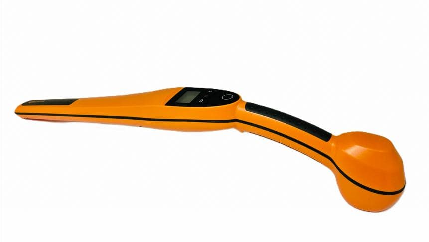
Apr 24, 2026Handheld EID Tag Reader HR0
Equipment Class
DCD - Part 15 Low Power Transmitter Below 1705 kHz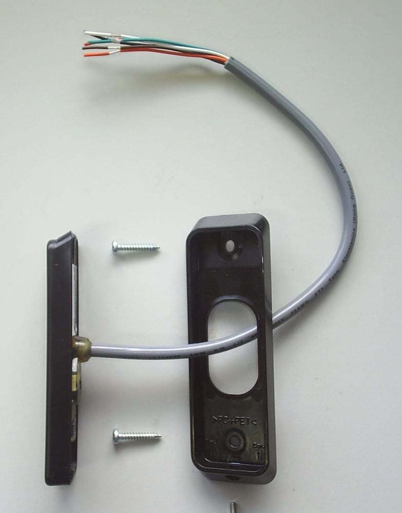
M5VC30040XB
Mar 28, 2023Prox Readers T10 Mifare
Equipment Class
DXX - Part 15 Low Power Communication Device Transmitter
M5VC30047XB
Feb 16, 2022Prox Readers T15 Mifare
Equipment Class
DXT - Part 15 Low Power Transceiver, Rx Verified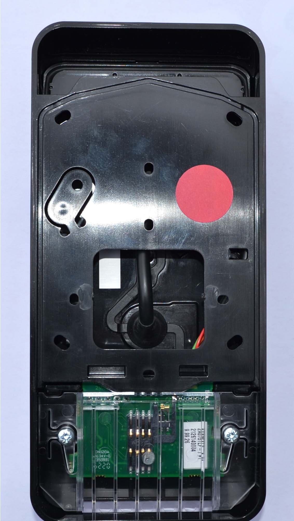
M5VC30550X
Jul 28, 2021Prox Readers T21 PIV
Equipment Class
DXT - Part 15 Low Power Transceiver, Rx Verified
M5VC30049X
Aug 19, 2020Prox Readers T30
Equipment Class
DXT - Part 15 Low Power Transceiver, Rx Verified