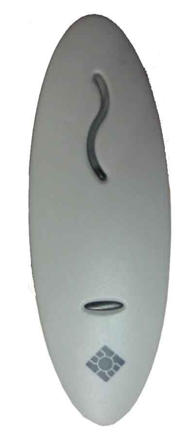
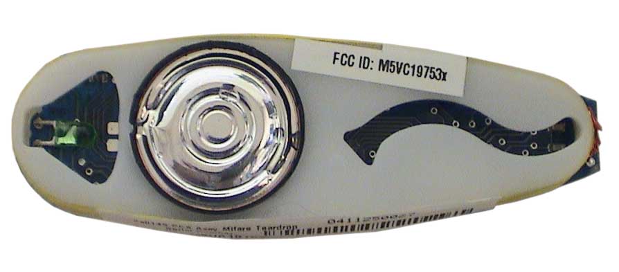
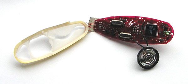
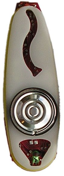
M5VC19753XProx Reader Mifare (Teardrop)
Gallagher Group Ltd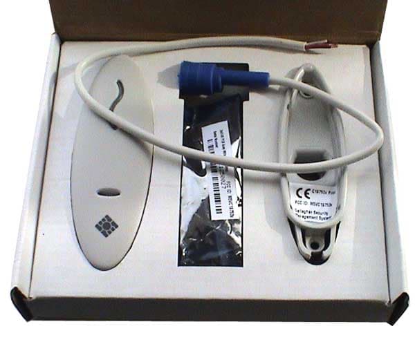
Click to zoom
Application Details
- Equipment Class
- DXT - Part 15 Low Power Transceiver, Rx Verified
- Date of Grant
- Sep 22, 2004
- Application Purpose
- Original Equipment
- Date of Application
- Sep 22, 2004
- Equipment Note
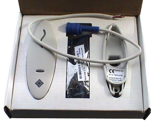
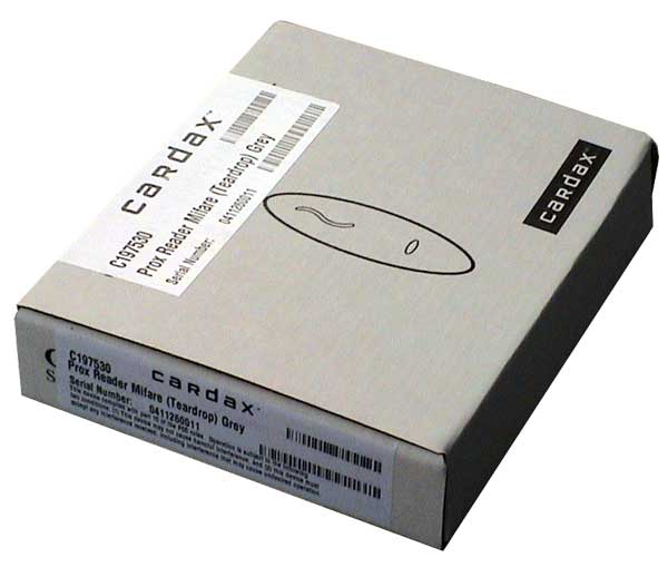
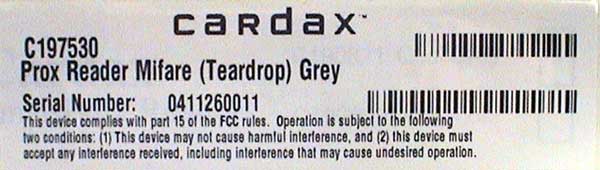
- Prox Reader Mifare (Teardrop)
- Frequency Range
- 13.56000000 - 13.56000000
- Company
- Gallagher Group Ltd
- Country
- New Zealand
Documents & Files
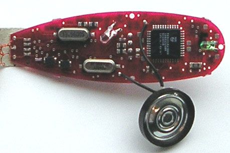
Document Text
Text extracted from the exhibit documents filed with the FCC. Open a document above to read the original.
Users Manual
Installation Note Part number 3E1100 R3 1 September 2004 CAUTION This equipment contains components that can be damaged by electrostatic discharge. Ensure both you and the equipment are earthed before beginning any servicing. 3E1100 R1 April 2004 Before you Begin Unpack the Prox Mifare Series (Teardrop) reader and check the shipment contains the following items: • 1 x Prox Mifare Series (Teardrop) reader base • 1 x Prox Mifare Series (Teardrop) reader facia • 1 x printed circuit board (PCB) assembly • 2 x self tapper pan head fixing screws • 1 x cable assembly Power Supply Requirements Power for the Prox Mifare Series (Teardrop) reader is usually taken from the incoming supply of the device to which it is connected. That is, from the: • Cardax FT Reader I/O Interface • Cardax FT Controller 3000 • Cardax FT Universal Reader Interface (Cardax FT URI) • Cardax Commander Universal Reader Interface (Cardax Commander URI). The supply at the reader should be 13.6 V DC ± 15%. The current draw is 180 mA per reader. This is in addition to the requirements of any other device (for example, the URI) powered from the same supply. Prox Mifare Series (Teardrop) 2 Part number 3E1100 R3 September 2004 Prox Mifare Series (Teardrop) readers require a good quality linear power source. If you do not use the recommended power supply, it may affect the performance of the reader. Note: Switch mode power supplies are not recommended as they may reduce the read range of the Prox Mifare Series (Teardrop) reader. Cabling The Prox Mifare Series (Teardrop) reader uses the Cardax IV communications system. This means it can be connected to the following Cardax equipment: • Cardax FT Reader I/O Interface • Cardax FT Controller 3000 • Cardax FT URI • Cardax Commander URI Use 4 core, 0.2 mm 2 (AWG 24) cabling with a maximum, nominal capacitance of 120 pf/m. The maximum external diameter of the cable must not exceed 5 mm (1/5 inch). With this type of cable, the maximum distance between the Prox Mifare Series (Teardrop) reader and the device to which it connects is 200 m (650 ft). Note: You need a special cable terminating tool to connect the building cabling to the Prox Mifare Series (Teardrop) reader. The tool has a head (Part No. C861145) and handle (Part No. C861115). You also need a special tool (Part No. C41611 ) to open the Prox Mifare Series (Teardrop) reader if necessary. Mounting Distance Between Proximity Readers The distance between any 2 proximity readers must be greater than 200mm in all directions. Part number 3E1100 R3 3 September 2004 Please note that 200mm in all directions includes the distance through walls. Wall Proximity Reader Proximity Reader Less than 200mm thick Mounting Note: The Prox Mifare Series (Teardrop) reader has been designed to metric specifications. Therefore any imperial measurements provided are approximate only. The Prox Mifare Series (Teardrop) reader is designed to be mounted on any solid flat surface, however metal surfaces can result in a reduced read range. Note: The grommet through which the cables feed into the base of the Prox Mifare Series (Teardrop) reader helps to keep the unit waterproof. Using the mounting dimensions on the back of this Installation Note as a guide, drill a 20 mm ( 3 / 4 inch) diameter hole for the base extrusion through or into the mounting surface to a minimum depth of 40 mm (1 1 / 2 in). Drill two pilot holes for the fixing screws. Run the building cabling through the base and grommet. 4 Part number 3E1100 R3 September 2004 Fit the base to the 20 mm ( 3 / 4 inch) hole and secure it to the mounting surface using the two fixing screws provided. Note that using other types of screws could interfere with the electronics. Note: It is very important that the base of the reader is flush with and tight against the mounting surface. If you are mounting the Prox Mifare Series (Teardrop) reader on a rough surface you should make the surface as smooth as possible under the reader and up to 25mm (1 in) around the reader. This is to enable easy removal at a later date is required. Push the socket back into the grommet. Push the grommet and socket back into the Prox Mifare Series (Teardrop) reader base. Check the tape covering the antenna wire solder joints is in position. Install the PCB assembly into the base, ensuring the connector on the back of the PCB assembly fits into the socket in the base. The PCB assembly should click into place. Fit the facia onto the base by clipping the small lip, inside the facia, over the top edge of the base and holding the top, press the bottom of the facia down until it clicks onto the bottom of the base. Removing the Facia To remove the facia from the Prox Mifare Series (Teardrop) reader base you need the plastic de-latching tool (Part No. 41611) shown below. The end of the tool is used for removing the facia. De-latching tool Part number 3E1100 R3 5 September 2004 1. Slide the de-latching tool firmly under the bottom of the Prox Mifare Series (Teardrop) reader. 2. Hold the top of the Prox Mifare Series (Teardrop) reader with your fingers and squeeze the de-latching tool up, towards the top of the reader with your thumb. 3. Lift the facia away from the base. If the base is not flush to the wall, or the screws have become loose you may need to pack the space between the de-latching tool and the wall. A thin piece of cardboard is usually all that is necessary, (i.e. a business card folded in two). 4. Cut a notch in the folded edge of the card similar in shape to the notch in the de-latching tool as shown below. 5. Slide the card under the bottom of the facia and then use the de-latching tool with the card as packing. Connections The Prox Mifare Series (Teardrop) reader connects to one of the following: • Cardax FT Reader I/O Interface • Cardax FT Controller 3000 • Cardax FT URI • Cardax Commander URI Use the cable terminating tool to connect the cables to the socket as described in the following sections. Pin number 4 of the Prox Mi…
Text truncated - open the document above for the full version.
Cover Letter(s)
Gallagher Group Ltd 181 Kahikatea Drive Private Bag 3026 Hamilton, New Zealand Tel: +64-7-838-9800 Fax: +64-7-838-9801 Email: [email protected] www.gallaghergroup.co.nz Federal Communication Commission Equipment Authorization Division, Application Processing Branch 7435 Oakland Mills Road Columbia, MD 21048 June 29, 2004 TO WHOM IT MAY CONCERN Pursuant to Paragraphs §0.457 and 0.459 of the Commission’s Rules (47 C.F.R.) and Section §552(b)(4) of the Freedom of Information Act, Gallagher Group Ltd requests confidentiality for the following products: FCC ID Number Product Title/Model M5VC19753x Prox Reader Mifare (Teardrop) For the product stated above, we request that the following information be held confidential: 1) Electrical Schematics of the Circuitry 2) Block Diagram 3) Operational Description No other items submitted as part of the equipment authorisation filing process are deemed confidential. The above exhibits contain Gallagher Group Ltd trade secrets and proprietary information that could be of benefit to our competitors regarding the design of our Prox Reader. This material is not customarily available to the general public and we request that it be withheld from public inspection. If you have any questions, please feel free to contact me at the address shown below. Sincerely, Dave Grant Test Engineer Gallagher Group Ltd Kahikatea Drive Hamilton New Zealand Phone: 64 7 838-9829 Fax: 64 7 838-9801 Companies Gallagher Group Ltd – NZ Sunplas Engineering (82) Ltd – NZ Gallagher Security (int) Ltd – NZ Gallagher Power Fence (SA) Pty – Sth Africa Gallagher Security (UK) Ltd – UK Gallagher Security (USA) Inc – USA Franklin Machinery – New Zealand PEC Pumps PEC Fuel Pumps Ltd Cardax (International) Ltd Gallagher Finance & Management Ltd Gallagher IT Solutions Ltd Reach Global Ltd Associate Companies Gallagher Europe Veldman & Djikstra Gallagher Australia Pty Ltd – Australia Gallagher Insultimber – Australia Gallagher Power Fence Inc – USA Gallagher Power Fencing Systems Inc – Canada Gallagher Power Fence (IRL) Ltd – Ireland Ibex Gallagher – India A/S Poda Hegn – Denmark NZ Producciones S.A – Argentina International Scales Pty Ltd - Australia
Cover Letter(s)
From: Dave Grant [[email protected]] Sent: Wednesday, August 04, 2004 8:43 PM To: [email protected] Subject: Fw: Non-Conformities FCC ID: M5VC19753x (Ref # E04-000067-1) Hello Randy, Item 7 has now also been completed. Please refer to the exhibits. All of the non-confomance issues that you have raised have now been addressed. Please let me know if you have any further questions. Regards ... Dave Grant Compliance Engineer Alison Laboratories Ltd DDI: +64 7 838-9829 Fax: +64 7 838-9801 ----- Forwarded by Dave Grant/GGL on 05/08/2004 03:40 p.m. ----- Dave Grant/GGL 05/08/2004 01:22 To p.m. <[email protected]> cc Subject Fw: Non-Conformities FCC ID: M5VC19753x (Ref # E04-000067-1) Hello Randy, Please note that Item 8 has been completed. Please refer to the exhibits. Regards ... Dave Grant Compliance Engineer Alison Laboratories Ltd DDI: +64 7 838-9829 Fax: +64 7 838-9801 ----- Forwarded by Dave Grant/GGL on 05/08/2004 01:20 p.m. ----- Dave Grant/GGL 05/08/2004 12:54 To p.m. <[email protected]> cc Subject Re: Non-Conformities FCC ID: M5VC19753x (Ref # E04-000067-1) (Document link: Dave Grant) Hello Randy, I am working on a number of the nonconformity's that you have actioned against our submission. The status of these is as follows: Item 1. Completed. See attached file Item 2. I have incorrectly stated the frequency on the submission. This should be 13.56MHz Item 3. The transponder does not have a return frequency. It dampens the reader frequency as a form of communication with the reader. Item 4. Completed. Please refer to the exhibits Item 5. Completed. Please refer to the exihibits. Item 6. Completed. Please refer to the exihibits Item 7. In progress Item 8. In progress Item 9. Completed. Please refer to the exihibits I will follow up with the remaining two items as these become available to me. (Embedded image moved to file: pic27446.jpg) Regards ... Dave Grant Compliance Engineer Alison Laboratories Ltd DDI: +64 7 838-9829 Fax: +64 7 838-9801 <info@ckccertific ation.com> To 04/08/2004 05:59 [email protected] p.m. cc Subject Non-Conformities FCC ID: M5VC19753x (Ref # E04-000067-1) Non-Conformities FCC ID: M5VC19753x (Ref # E04-000067-1) The items listed below represent requests for information following review of this application. Further question may arise pending review of responses to these items. Item 1. Although it is the general consensus at CKC CS that your company had previously provided this, a signed CKC CS General Agreement could not be located in our records. Please provide a singed copy of the CKC CS general agreement. This document may either be submitted digitally or faxed to our office at +1 209 742 6133. Item 2. The frequency range listed on the form 731 is inconstant with that listed in the test report. Please clarify. Does the equipment additionally operate on 125kHz? Item 3. Please provide the tag return frequency. Item 4. Per ANSI C63.4, please update the test report to include the calibration dates of all test equipment used during testing.. Item 5. Although external photos of the packaging have been included. 47 CFR 2.1033(b)(7) refers to external photos of the exterior of the device. Please provide detailed photographs of the exterior of the equipment without packaging. Item 6. In accordance with 47 CFR 2.1033(b)(8), the test report should include a description of the peripheral equipment used during testing. Please provide. Item 7. In the provided FCC ID label placement photo, the ID label has easily accessible edges such that it appears that the ID label could be easily removed. Please clarify how this placement satisfies the requirement for the FCC ID to be a permanent part of or an attachment to the equipment. Item 8. Please provide an updated users manual incorporating the appropriate manual statement in accordance with 15.21, modifications to the equipment. Item 9. On page 7 or 21 of the test report, the data indicate reading above the specified limit, which would indicate that the equipment is not compliant with the emissions limits of 15.207. Please explain. Please note that ANSI C63.4 allows the use of a dummy load when the equipment employs a detachable antenna. The items indicated above must be submitted before processing can continue on the referenced application. Failure to provide the requested information within 60 days may result in application dismissal pursuant to Section 2.917(c) and forfeiture of the filing fee pursuant to Section 1.1106. All Best, Randy Clark CKC Certification Services.
Test Report
EMC Technologies (NZ) Ltd Test Report No 40333.1c Report date: 15 th September 2004 __________________________________________________________________________________________________________________________________________________________________________________ EMC Technologies (NZ) Ltd Telephone: +64 9 360 0862 Fax: +64 9 360 0861 STREET ADDRESS - 47 MacKelvie Street, Grey Lynn, Auckland, New Zealand E-mail: [email protected] POSTAL ADDRESS - PO Box 68 307, Newton, Auckland, New Zealand Web Site: www.emctech.com.au Page 1 of 22 This report may not be reproduced except in full TEST REPORT Cardax Mifare Tear Drop Proximity Card Reader tested to 47 Code of Federal Regulations Part 15 - Radio Frequency Devices Subpart C – Intentional Radiators for Gallagher Group Ltd This Test Report is issued with the authority of: ______________________________________ Andrew Cutler - General Manager Prepared By: ______________________________________ Cecilia Lam - Office Administrator EMC Technologies (NZ) Ltd Test Report No 40333.1c Report date: 15 th September 2004 __________________________________________________________________________________________________________________________________________________________________________________ EMC Technologies (NZ) Ltd Telephone: +64 9 360 0862 Fax: +64 9 360 0861 STREET ADDRESS - 47 MacKelvie Street, Grey Lynn, Auckland, New Zealand E-mail: [email protected] POSTAL ADDRESS - PO Box 68 307, Newton, Auckland, New Zealand Web Site: www.emctech.com.au Page 2 of 22 This report may not be reproduced except in full Table of Contents 1. STATEMENT OF COMPLIANCE 3 2. RESULTS SUMMARY 3 3. INTRODUCTION 4 4. CLIENT INFORMATION 4 5. DESCRIPTION OF TEST SAMPLE 5 6. RESULTS 6 7. TEST EQUIPMENT USED 17 8. ACCREDITATIONS 17 9. PHOTOGRAPH (S) 18 EMC Technologies (NZ) Ltd Test Report No 40333.1c Report date: 15 th September 2004 __________________________________________________________________________________________________________________________________________________________________________________ EMC Technologies (NZ) Ltd Telephone: +64 9 360 0862 Fax: +64 9 360 0861 STREET ADDRESS - 47 MacKelvie Street, Grey Lynn, Auckland, New Zealand E-mail: [email protected] POSTAL ADDRESS - PO Box 68 307, Newton, Auckland, New Zealand Web Site: www.emctech.com.au Page 3 of 22 This report may not be reproduced except in full 1. STATEMENT OF COMPLIANCE The Cardax Mifare Tear Drop Proximity Card Reader complies with FCC Part 15 Subpart C as an Intentional Radiator when the methods, as described in ANSI C63.4 - 1992, are applied. 2. RESULTS SUMMARY Clause Parameter Result 15.201 Equipment authorisation requirement Certification required. 15.203 Antenna requirement Complies. Antenna connector unique. 15.204 External PA and antenna modifications Not applicable. No external devices. 15.205 Restricted bands of operation Complies. Device transmits on 13.561 MHz 15.207 Conducted limits Complies with a 0.53 dB margin at 13.561 MHz (Quasi Peak). 15.209 Radiated emission limits Complies with a 0.7 dB margin at 176.290 MHz. 15.225 a Fundamental emission Complies with a 60.3 dB margin 15.225 a-d Fundamental emission mask Complies. 15.225 e Frequency tolerance Complies EMC Technologies (NZ) Ltd Test Report No 40333.1c Report date: 15 th September 2004 __________________________________________________________________________________________________________________________________________________________________________________ EMC Technologies (NZ) Ltd Telephone: +64 9 360 0862 Fax: +64 9 360 0861 STREET ADDRESS - 47 MacKelvie Street, Grey Lynn, Auckland, New Zealand E-mail: [email protected] POSTAL ADDRESS - PO Box 68 307, Newton, Auckland, New Zealand Web Site: www.emctech.com.au Page 4 of 22 This report may not be reproduced except in full 3. INTRODUCTION This report describes the tests and measurements performed on the Cardax Mifare Tear Drop Proximity Card Reader for the purpose of determining compliance with the specification. The client selected the test sample. This report relates only to the sample tested. This report contains no corrections or erasures. Measurement uncertainties with statistical confidence intervals of 95% are shown below test results. Both Class A and Class B uncertainties have been accounted for, as well as influence uncertainties where appropriate. This report replaced report 40333.1b in order to address several further issues raised by a Telecommunication Certification Body. 4. CLIENT INFORMATION Company Name Gallagher Group Ltd Address Private Bag 3026 City Hamilton Country New Zealand Contact Mr Dave Grant EMC Technologies (NZ) Ltd Test Report No 40333.1c Report date: 15 th September 2004 __________________________________________________________________________________________________________________________________________________________________________________ EMC Technologies (NZ) Ltd Telephone: +64 9 360 0862 Fax: +64 9 360 0861 STREET ADDRESS - 47 MacKelvie Street, Grey Lynn, Auckland, New Zealand E-mail: [email protected] POSTAL ADDRESS - PO Box 68 307, Newton, Auckland, New Zealand Web Site: www.emctech.com.au Page 5 of 22 This report may not be reproduced except in full 5. DESCRIPTION OF TEST SAMPLE Brand Name Cardax Model Number Mifare Tear Drop Card Reader Product Proximity Card Reader Manufacturer Gallagher Group Ltd Country of Origin New Zealand Serial Number 0435461117 Ancillary Equipment: Alarm SAF MPS-U12030-B03-UL Power Support System (110 Vac to 12 Vdc external power supply). Serial number #049853. Cardax 190200 Univeral Reader Interface. Serial number #19841. Photographs of this equipment are attached. The following changes have been made to the device: The external ferrite choke that previously needed to be fitted to the supply cable to the transmitter is no longer required and has been removed. In order to comply with the conducted emission requirements a software modification has been made to the device whereby the transmitter duty …
Text truncated - open the document above for the full version.
Test Setup Photos
EMC Technologies (NZ) Ltd Test Report No 40333.1c Report date: 15 th September 2004 __________________________________________________________________________________________________________________________________________________________________________________ EMC Technologies (NZ) Ltd Telephone: +64 9 360 0862 Fax: +64 9 360 0861 STREET ADDRESS - 47 MacKelvie Street, Grey Lynn, Auckland, New Zealand E-mail: [email protected] POSTAL ADDRESS - PO Box 68 307, Newton, Auckland, New Zealand Web Site: www.emctech.com.au Page 20 of 22 This report may not be reproduced except in full Conducted emissions Test Set Up EMC Technologies (NZ) Ltd Test Report No 40333.1c Report date: 15 th September 2004 __________________________________________________________________________________________________________________________________________________________________________________ EMC Technologies (NZ) Ltd Telephone: +64 9 360 0862 Fax: +64 9 360 0861 STREET ADDRESS - 47 MacKelvie Street, Grey Lynn, Auckland, New Zealand E-mail: [email protected] POSTAL ADDRESS - PO Box 68 307, Newton, Auckland, New Zealand Web Site: www.emctech.com.au Page 21 of 22 This report may not be reproduced except in full Radiated Emissions Test Set Up EMC Technologies (NZ) Ltd Test Report No 40333.1c Report date: 15 th September 2004 __________________________________________________________________________________________________________________________________________________________________________________ EMC Technologies (NZ) Ltd Telephone: +64 9 360 0862 Fax: +64 9 360 0861 STREET ADDRESS - 47 MacKelvie Street, Grey Lynn, Auckland, New Zealand E-mail: [email protected] POSTAL ADDRESS - PO Box 68 307, Newton, Auckland, New Zealand Web Site: www.emctech.com.au Page 22 of 22 This report may not be reproduced except in full Ancillary equipment set up
Contact Information
Applicant
Tony Smith(Hardware Development Manager)
Technical Contact
Gallagher Group, Ltd.Dave Grant
[email protected]+64 7 838-9829
181 Kahikatea Dr. · Hamilton · New Zealand
Non-Technical Contact
Gallagher Group, Ltd.Dave Grant
[email protected]+64 7 838-9829
Test Firm
EMC Technologies NZ Ltd.Andrew Cutler
Technical Specifications
| # | Rule Parts | Frequency Range | Power Output |
|---|---|---|---|
| 1 | 15C | 13.56 MHz - 13.56 MHz | - |
Other Applications from Gallagher Group Ltd
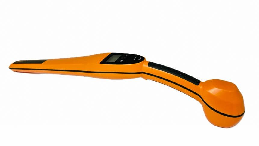
M5VG03307
Apr 24, 2026Handheld EID Tag Reader HR0
Equipment Class
DCD - Part 15 Low Power Transmitter Below 1705 kHz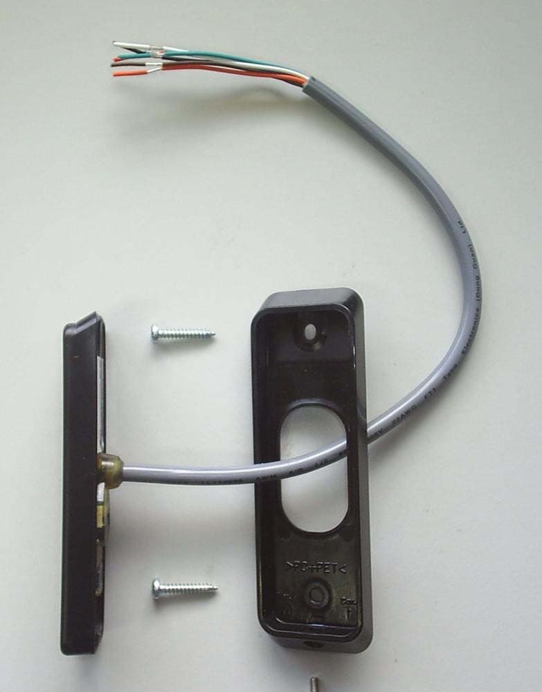
M5VC30040XB
Mar 28, 2023Prox Readers T10 Mifare
Equipment Class
DXX - Part 15 Low Power Communication Device Transmitter
M5VC30047XB
Feb 16, 2022Prox Readers T15 Mifare
Equipment Class
DXT - Part 15 Low Power Transceiver, Rx Verified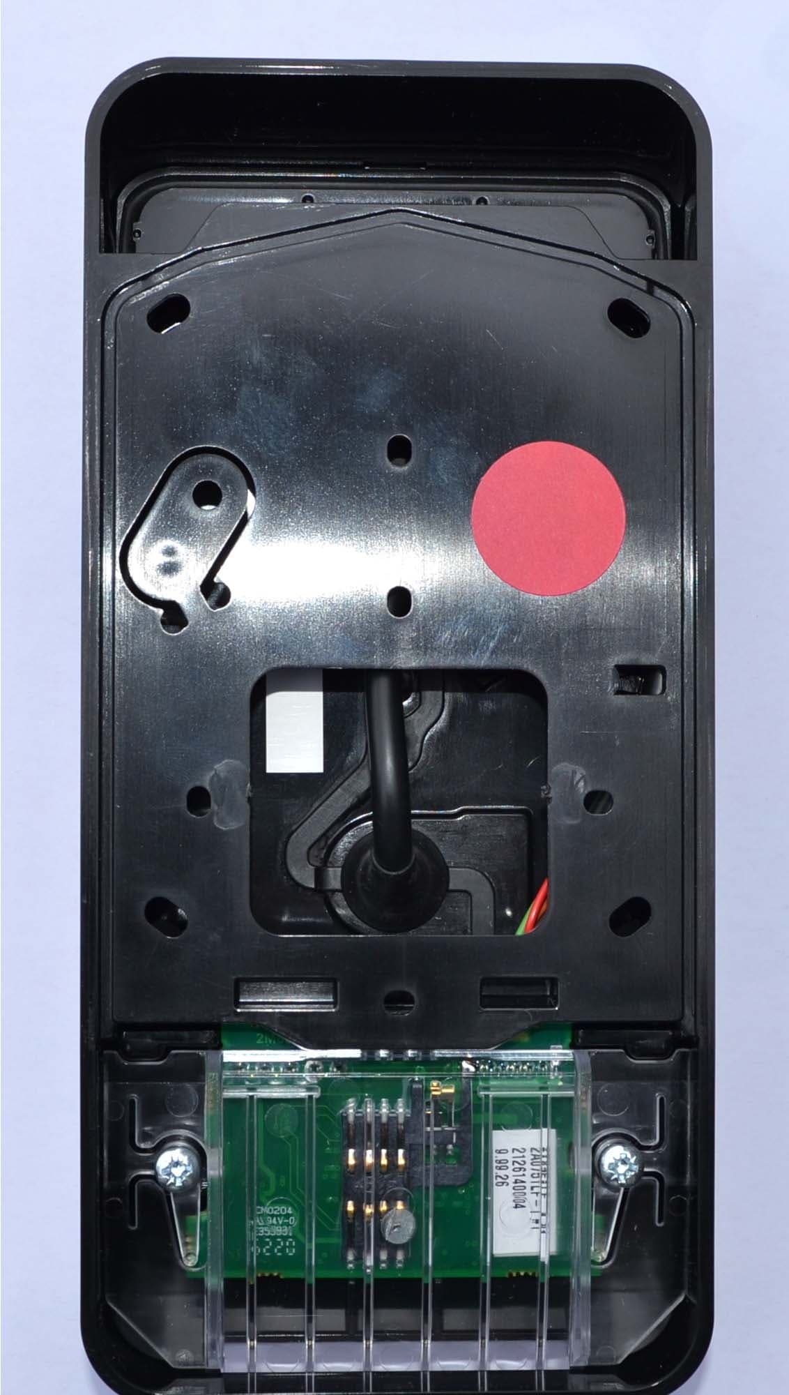
M5VC30550X
Jul 28, 2021Prox Readers T21 PIV
Equipment Class
DXT - Part 15 Low Power Transceiver, Rx Verified
M5VC30049X
Aug 19, 2020Prox Readers T30
Equipment Class
DXT - Part 15 Low Power Transceiver, Rx Verified