M5VC20024XFT IDT Mifare
Gallagher Group Ltd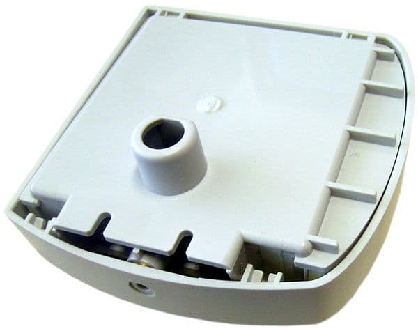
Click to zoom
Application Details
- Equipment Class
- DXT - Part 15 Low Power Transceiver, Rx Verified
- Date of Grant
- Jun 30, 2005
- Application Purpose
- Original Equipment
- Date of Application
- Jun 30, 2005
- Equipment Note
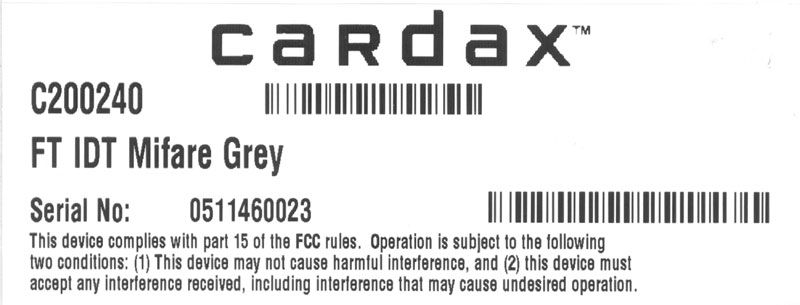
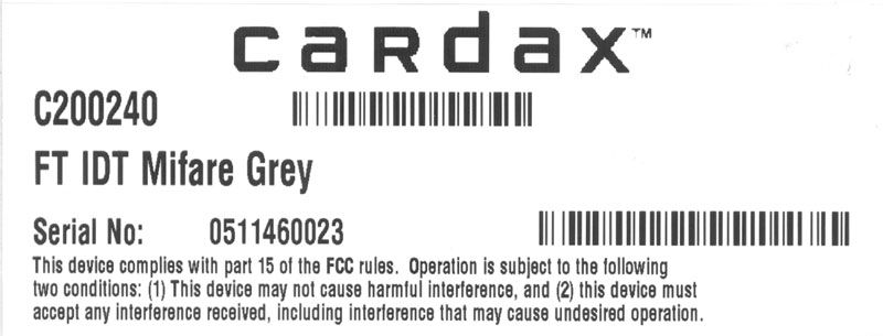
- FT IDT Mifare
- Frequency Range
- 13.56000000 - 13.56000000
- Company
- Gallagher Group Ltd
- Country
- New Zealand
Documents & Files
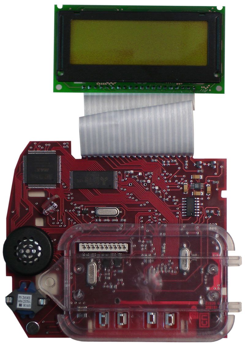
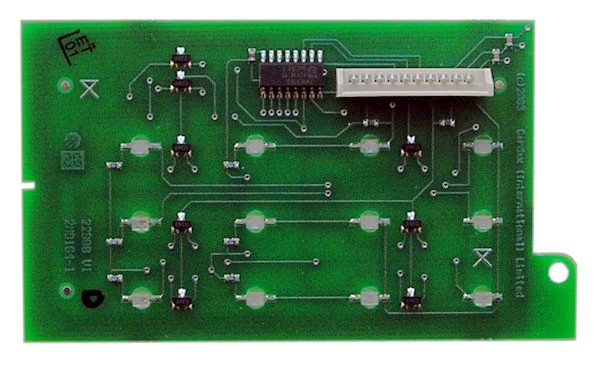
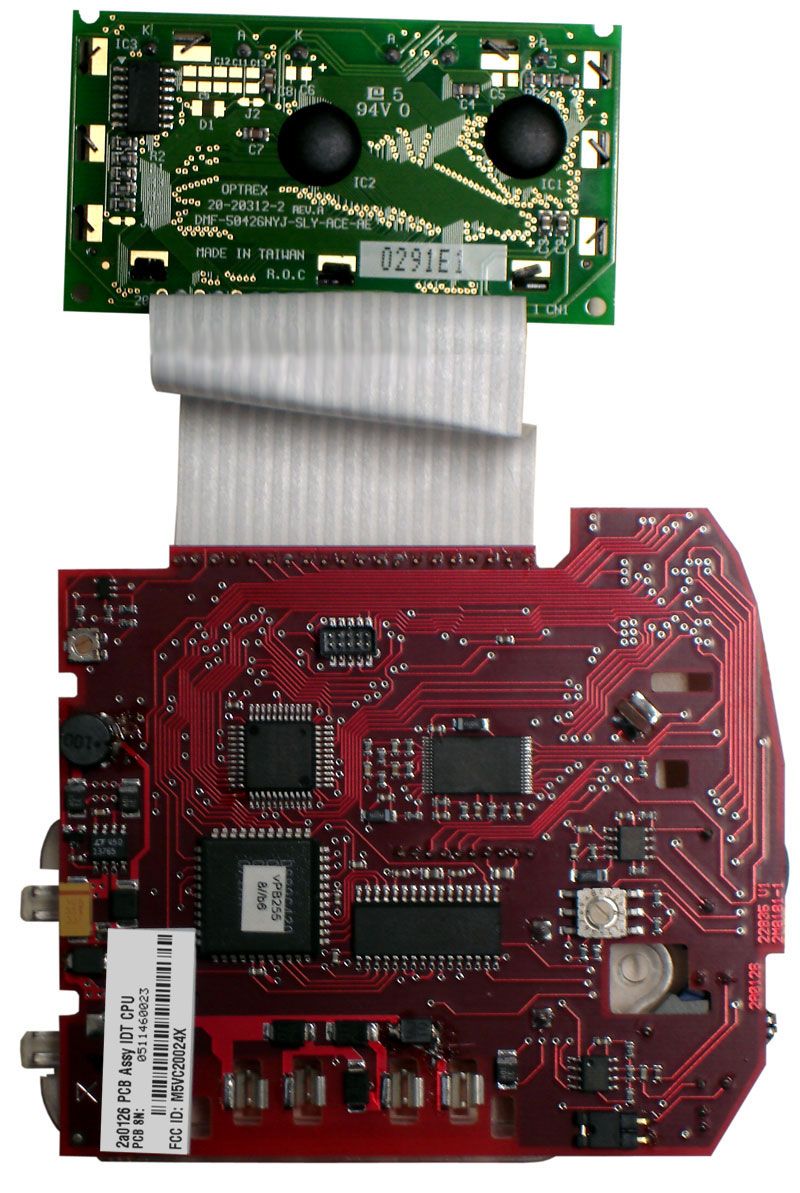
Document Text
Text extracted from the exhibit documents filed with the FCC. Open a document above to read the original.
Users Manual
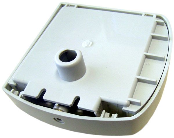
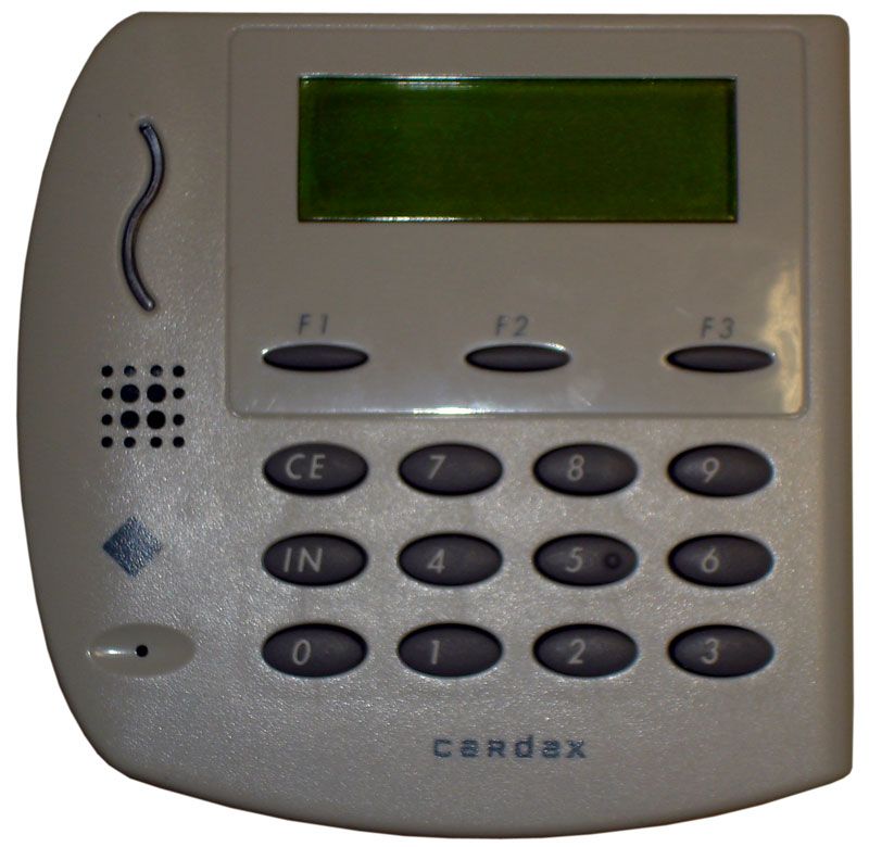
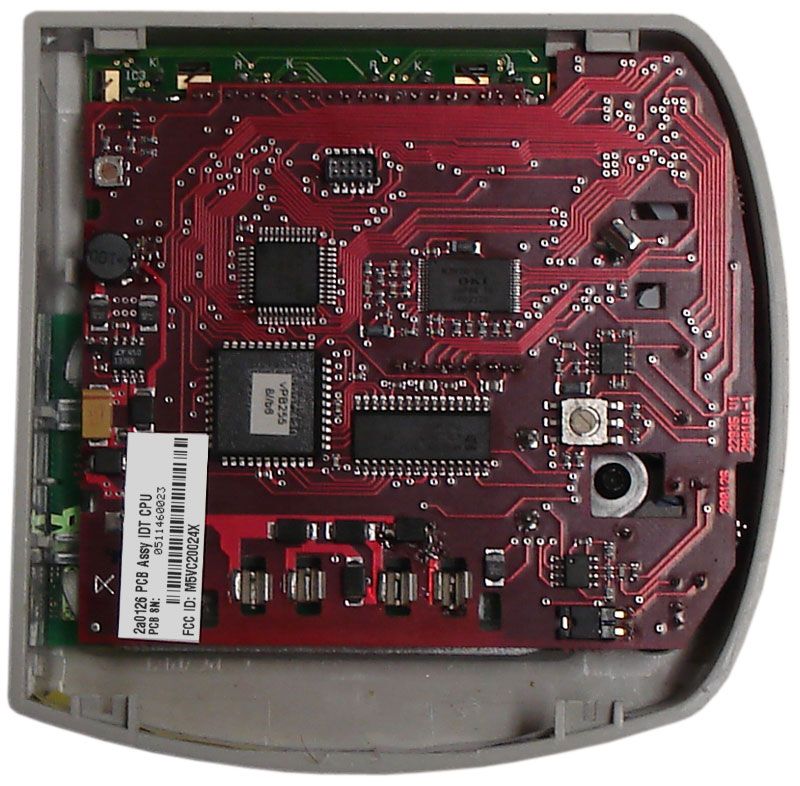
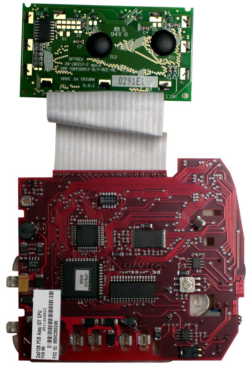
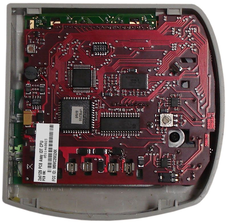
Part number 3B3957 R8 1 June 2005 Installation Note CAUTION This equipment contains components that can be damaged by electrostatic discharge. Ensure both you and the equipment are earthed before beginning any servicing. The Cardax FT Intelligent Door Terminal (Mifare Series) The Cardax FT Intelligent Door Terminal Mifare Series (IDT) is a "remote" proximity tag reader with text display and an inbuilt intercom. The IDT can be installed as either an entry and/or exit reader, and the intercom enables communication with the console operator. The IDT has a back-lit keypad and an inbuilt Liquid Crystal Display (LCD). The LCD can display both text and graphics to aid the Cardholder. The IDT sends information to the Cardax FT Controller and acts upon information sent from the Cardax FT Controller. The IDT itself does not make any decisions. A Cardax FT IDT Cover can be fitted over the IDT to prevent the IDT being damaged by vandal attack and to increase protection against harsh weather. Refer to the Prox Reader and IDT Covers Installation Note (part number 3C4589). Cardax FT Intelligent Door Terminal (Mifare Series) 2 Part number 3B3957 R8 June 2005 Before you begin Shipment contents Open the box and check that the following items have been supplied: • 1 x Cardax FT IDT Mifare Base. • 1 x Cardax FT IDT Mifare facia assembly (includes printed circuit boards, processor, display and keypad). • 1 x interconnect printed circuit board. • 1 x copy of this installation note. • 1 x cable assembly. • 4 x pan-head self-tapping screws. • 4 x screw caps. • 1 x M4x12, tamper-resistant, Torx-head machine screw. Software The IDT requires version vMP3.00 or later of software code, which you can download from your Cardax FT Command Centre Installation CD-ROM. If the CD-ROM does not have vMP3.00 or later of IDT code on it, the code can be downloaded from the Cardax website. Once you have the correct IDT code, it then needs to be downloaded to the IDT. To do this, refer to "Adding a new version of Device Software" for the procedure, in the Cardax FT Command Centre User Guide (part number C209000). Power Supply Requirements The IDT draws 300 mA from a 13.6 V ±15% DC supply. This means that with the reader operating, the voltage measured across pins 1 and 4 on the interconnect printed circuit board should be at least 11.6 V. It is recommended that you dimension the cable to provide a minimum of 12 V at the IDT while it is operating. Use a well-regulated DC supply that incorporates good output filtering. Switch mode power supplies may reduce the card read range due to the electrical noise generated by the power supply switching circuits. Building cabling Run the building cabling before installing the IDT. Refer to Chapter 2 of Cardax FT Installation Manual for cabling details. Over short distances, you may run one cable carrying both the communications and DC supply. Over long distances, run separate cables for the DC supply and communications. In each case, verify that the correct supply voltage is present at the IDT. Part number 3B3957 R8 3 June 2005 RS485 communications Use high-quality, low-capacitance, twisted-pair cable. Category 5 (CAT 5) cable is suitable. DC power Ensure the cable size is adequate for correct operation of the IDT. Mounting Note: The IDT has been designed to metric specifications, therefore any imperial measurements provided are approximate only. The IDT is designed to mount on any solid, flat surface. The card read range is reduced when the IDT is mounted on or near metal surfaces. Height The recommended mounting height for the IDT is 1100 mm, measured from the centre of the facia to the floor. Check your local regulations for any variations to this recommended height. Installation 1. Fit the base as described in Fastening the base to the mounting surface (on page 4). 2. Join the building cable to the connector tail and fit the Interconnect PCB as described in Joining the cable (on page 4). 3. Set the IDT address as described in Setting the unit address (on page 5). 4. Fit the facia as described in Fitting the facia (on page 6). 4 Part number 3B3957 R8 June 2005 Fastening the base to the mounting surface Note: It is important that the base of the IDT is flush with, and tight against, the mounting surface. If you are mounting the IDT on a rough surface, make the surface as smooth as possible under the IDT and up to 25 mm (1 inch) around the IDT. 1. Mark the position where the IDT is to be mounted. 2. Drill a 20 mm (¾ inch) diameter hole through the mounting surface for the base extrusion. 3. Optionally, drill four pilot holes for the four fixing screws. Note: Six possible mounting holes are provided in the base. Ensure the four you chose will hold the IDT securely. 4. Pass the building cable through the hole in the base extrusion. 5. Press the base extrusion into the 20 mm hole. Use the four pan-head self- tapping screws to fasten the base to the mounting surface. 6. Press a plastic cap into the socket over each screw head. The plastic caps prevent water from entering the IDT through the fixing holes. Joining the cable 1. Join the connector tail cable to the building cable. Red: DC supply positive White: RS485 communications cable Blue: RS485 communications cable Black: DC supply negative (0 V, GND) Note: The Cardax FT system does not require the RS485 communications cable to be polarised. The DC supply must be connected to the correct terminals. 2. Press the connector into the grommet. 3. Press the connector onto the mating plug on the Interconnect PCB. 4. Push the Interconnect PCB back so that the connector and grommet slide into the base extrusion. Press the Interconnect PCB until it locks under the retaining clips. Part number 3B3957 R8 5 June 2005 When to terminate the communications cable If this IDT is the last unit on the communications cable run, verify that the RS485 termination link is in place. If this IDT is not the last unit on the cable run, remove the link. The location of thi…
Text truncated - open the document above for the full version.
Cover Letter(s)
Gallagher Group Ltd 181 Kahikatea Drive Private Bag 3026 Hamilton, New Zealand Tel: +64-7-838-9800 Fax: +64-7-838-9801 Email: [email protected] www.gallaghergroup.co.nz Federal Communication Commission Equipment Authorization Division, Application Processing Branch 7435 Oakland Mills Road Columbia, MD 21048 June 17, 2005 TO WHOM IT MAY CONCERN Pursuant to Paragraphs §0.457 and 0.459 of the Commission’s Rules (47 C.F.R.) and Section §552(b)(4) of the Freedom of Information Act, Gallagher Group Ltd requests confidentiality for the following products: FCC ID Number Product Title/Model M5VC20024x FT IDT Mifare For the product stated above, we request that the following information be held confidential: 1) Electrical Schematics of the Circuitry 2) Block Diagram 3) Operational Description No other items submitted as part of the equipment authorisation filing process are deemed confidential. The above exhibits contain Gallagher Group Ltd trade secrets and proprietary information that could be of benefit to our competitors regarding the design of our Prox Reader. This material is not customarily available to the general public and we request that it be withheld from public inspection. If you have any questions, please feel free to contact me at the address shown below. Sincerely, Dave Grant Compliance Engineer Gallagher Group Ltd Companies Gallagher Group Ltd – NZ Sunplas Engineering (82) Ltd – NZ Gallagher Security (int) Ltd – NZ Gallagher Power Fence (SA) Pty – Sth Africa Gallagher Security (UK) Ltd – UK Gallagher Security (USA) Inc – USA Franklin Machinery – New Zealand PEC Pumps PEC Fuel Pumps Ltd Cardax (International) Ltd Gallagher Finance & Management Ltd Gallagher IT Solutions Ltd Reach Global Ltd Associate Companies Gallagher Europe Veldman & Djikstra Gallagher Australia Pty Ltd – Australia Gallagher Insultimber – Australia Gallagher Power Fence Inc – USA Gallagher Power Fencing Systems Inc – Canada Gallagher Power Fence (IRL) Ltd – Ireland Ibex Gallagher – India A/S Poda Hegn – Denmark NZ Producciones S.A – Argentina International Scales Pty Ltd - Australia
Test Report
EMC Technologies (NZ) Ltd Test Report No 50534.1 Report date: 27 May 2005 __________________________________________________________________________________________________________________________________________________________________________________ EMC Technologies (NZ) Ltd Telephone: +64 9 360 0862 Fax: +64 9 360 0861 STREET ADDRESS - 47 MacKelvie Street, Grey Lynn, Auckland, New Zealand E-mail: [email protected] POSTAL ADDRESS - PO Box 68 307, Newton, Auckland, New Zealand Web Site: www.emctech.com.au Page 1 of 21 This report may not be reproduced except in full TEST REPORT Cardax IDT Mifare Card Reader tested to 47 Code of Federal Regulations Part 15 - Radio Frequency Devices Subpart C – Intentional Radiators for Gallagher Group Ltd This Test Report is issued with the authority of: ______________________________________ Andrew Cutler - General Manager EMC Technologies (NZ) Ltd Test Report No 50534.1 Report date: 27 May 2005 __________________________________________________________________________________________________________________________________________________________________________________ EMC Technologies (NZ) Ltd Telephone: +64 9 360 0862 Fax: +64 9 360 0861 STREET ADDRESS - 47 MacKelvie Street, Grey Lynn, Auckland, New Zealand E-mail: [email protected] POSTAL ADDRESS - PO Box 68 307, Newton, Auckland, New Zealand Web Site: www.emctech.com.au Page 2 of 21 This report may not be reproduced except in full Table of Contents 1. STATEMENT OF COMPLIANCE 3 2. RESULTS SUMMARY 3 3. INTRODUCTION 4 4. CLIENT INFORMATION 4 5. DESCRIPTION OF TEST SAMPLE 5 6. RESULTS 5 7. TEST EQUIPMENT USED 18 8. ACCREDITATIONS 18 9. PHOTOGRAPH (S) 19 EMC Technologies (NZ) Ltd Test Report No 50534.1 Report date: 27 May 2005 __________________________________________________________________________________________________________________________________________________________________________________ EMC Technologies (NZ) Ltd Telephone: +64 9 360 0862 Fax: +64 9 360 0861 STREET ADDRESS - 47 MacKelvie Street, Grey Lynn, Auckland, New Zealand E-mail: [email protected] POSTAL ADDRESS - PO Box 68 307, Newton, Auckland, New Zealand Web Site: www.emctech.com.au Page 3 of 21 This report may not be reproduced except in full 1. STATEMENT OF COMPLIANCE The Cardax IDT Mifare Reader complies with FCC Part 15 Subpart C as an Intentional Radiator when the methods, as described in ANSI C63.4 - 1992, are applied. 2. RESULTS SUMMARY Clause Parameter Result 15.201 Equipment authorisation requirement Certification required. 15.203 Antenna requirement Complies. Antenna connector unique. 15.204 External PA and antenna modifications Not applicable. No external devices. 15.205 Restricted bands of operation Complies. Device transmits on 13.560 MHz 15.207 Conducted limits Complies with a 1.5 dB margin at 29.9675 MHz (Average). 15.209 Radiated emission limits Complies with a 4.0 dB margin at 50.0 MHz (Vertical). 15.225 a Fundamental emission Complies with a 56.0 dB margin. 15.225 a-d Fundamental emission mask Complies. 15.225 e Frequency tolerance Complies EMC Technologies (NZ) Ltd Test Report No 50534.1 Report date: 27 May 2005 __________________________________________________________________________________________________________________________________________________________________________________ EMC Technologies (NZ) Ltd Telephone: +64 9 360 0862 Fax: +64 9 360 0861 STREET ADDRESS - 47 MacKelvie Street, Grey Lynn, Auckland, New Zealand E-mail: [email protected] POSTAL ADDRESS - PO Box 68 307, Newton, Auckland, New Zealand Web Site: www.emctech.com.au Page 4 of 21 This report may not be reproduced except in full 3. INTRODUCTION This report describes the tests and measurements performed on the Cardax IDT Mifare Card Reader for the purpose of determining compliance with the specification. The client selected the test sample. This report relates only to the sample tested. This report contains no corrections or erasures. Measurement uncertainties with statistical confidence intervals of 95% are shown below test results. Both Class A and Class B uncertainties have been accounted for, as well as influence uncertainties where appropriate. 4. CLIENT INFORMATION Company Name Gallagher Group Ltd Address Private Bag 3026 City Hamilton Country New Zealand Contact Mr Dave Grant EMC Technologies (NZ) Ltd Test Report No 50534.1 Report date: 27 May 2005 __________________________________________________________________________________________________________________________________________________________________________________ EMC Technologies (NZ) Ltd Telephone: +64 9 360 0862 Fax: +64 9 360 0861 STREET ADDRESS - 47 MacKelvie Street, Grey Lynn, Auckland, New Zealand E-mail: [email protected] POSTAL ADDRESS - PO Box 68 307, Newton, Auckland, New Zealand Web Site: www.emctech.com.au Page 5 of 21 This report may not be reproduced except in full 5. DESCRIPTION OF TEST SAMPLE Brand Name Cardax Model Number IDT Mifare Product Card Reader Manufacturer Gallagher Group Ltd Country of Origin New Zealand Serial Number Ancillary equipment Alarm SAF MPS-U12030-B03-UL Power Support System (110 Vac to 12 Vdc external power supply). Serial number #049853. Cardax FT Controller 5000 (Part no: C200111). Serial number #0023340123. 6. RESULTS Standard The sample was tested in accordance with 47 CFR Part 15 Subpart C. Methods and Procedures The measurement methods and procedures as described in ANSI C63.4 - 1992 were used. Section 15.201: Equipment authorisation requirement Certification as detailed in Subpart J of Part 2 is required for this device. Section 15.203: Antenna requirement As can be seen from the attached photographs the device has an internal unique antenna that cannot be easily accessed and therefore cannot be easily modified. Result : Complies. EMC Technologies (NZ) Ltd Test Report No 50534.1 Report date: 27 May 2005 ___________________________________________________________________________________________________________________…
Text truncated - open the document above for the full version.
Test Setup Photos
EMC Technologies (NZ) Ltd Test Report No 50534.1 Report date: 27 May 2005 __________________________________________________________________________________________________________________________________________________________________________________ EMC Technologies (NZ) Ltd Telephone: +64 9 360 0862 Fax: +64 9 360 0861 STREET ADDRESS - 47 MacKelvie Street, Grey Lynn, Auckland, New Zealand E-mail: [email protected] POSTAL ADDRESS - PO Box 68 307, Newton, Auckland, New Zealand Web Site: www.emctech.com.au Page 21 of 21 This report may not be reproduced except in full Radiated emissions test set up Conducted emissions test set up which includes the ancillaries
Contact Information
Applicant
Tony Smith(Hardware Development Manager)
Technical Contact
Test Firm
EMC Technologies NZ Ltd.Andrew Cutler
Technical Specifications
| # | Rule Parts | Frequency Range | Power Output |
|---|---|---|---|
| 1 | 15C | 13.56 MHz - 13.56 MHz | - |
Other Applications from Gallagher Group Ltd
M5VG03307
Apr 24, 2026Handheld EID Tag Reader HR0
Equipment Class
DCD - Part 15 Low Power Transmitter Below 1705 kHz
M5VC30040XB
Mar 28, 2023Prox Readers T10 Mifare
Equipment Class
DXX - Part 15 Low Power Communication Device Transmitter
M5VC30047XB
Feb 16, 2022Prox Readers T15 Mifare
Equipment Class
DXT - Part 15 Low Power Transceiver, Rx Verified
M5VC30550X
Jul 28, 2021Prox Readers T21 PIV
Equipment Class
DXT - Part 15 Low Power Transceiver, Rx Verified
M5VC30049X
Aug 19, 2020Prox Readers T30
Equipment Class
DXT - Part 15 Low Power Transceiver, Rx Verified