M5VC30022XProx Readers T11 Mifare and T12 Mifare
Gallagher Group Ltd
Click to zoom
Application Details
- Equipment Class
- DXT - Part 15 Low Power Transceiver, Rx Verified
- Date of Grant
- Apr 18, 2011
- Application Purpose
- Original Equipment
- Date of Application
- Apr 17, 2011
- Equipment Note
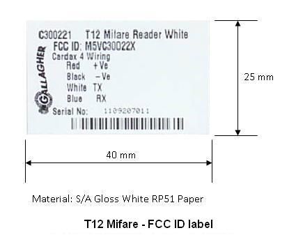
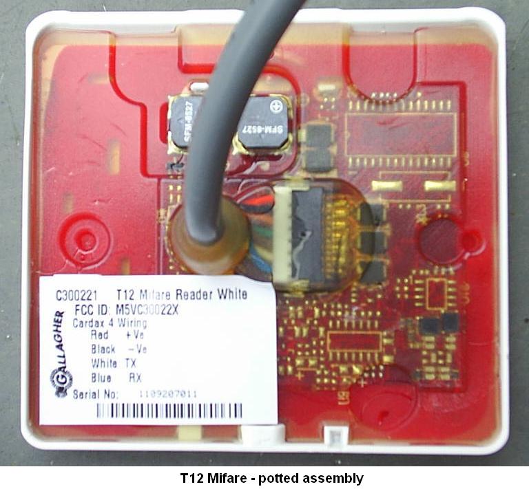
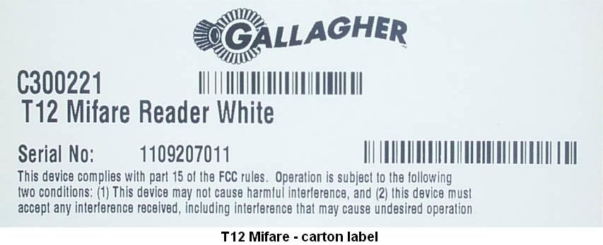
- Prox Readers T11 Mifare and T12 Mifare
- Frequency Range
- 13.56000000 - 13.56000000
- Company
- Gallagher Group Ltd
- Country
- New Zealand
Documents & Files
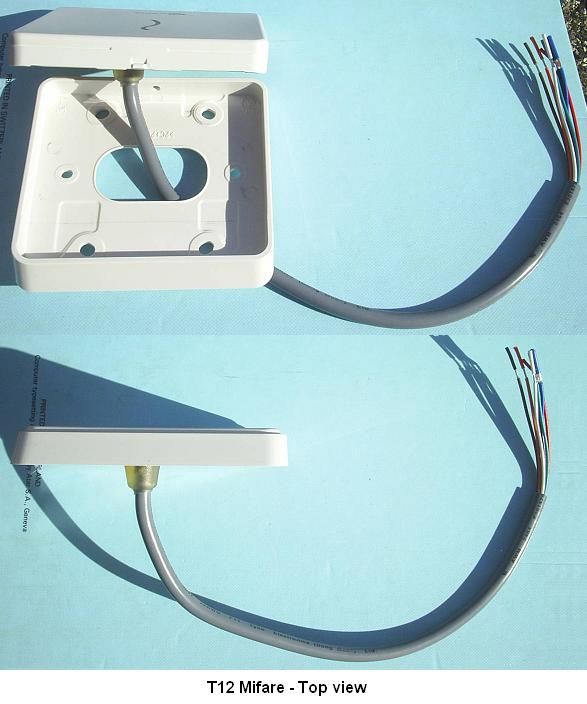
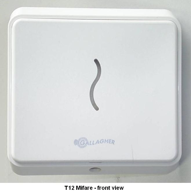
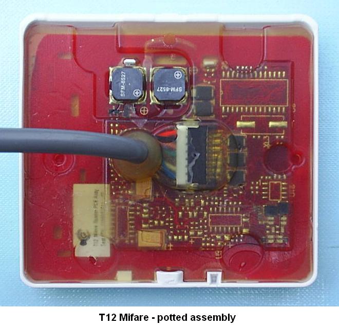
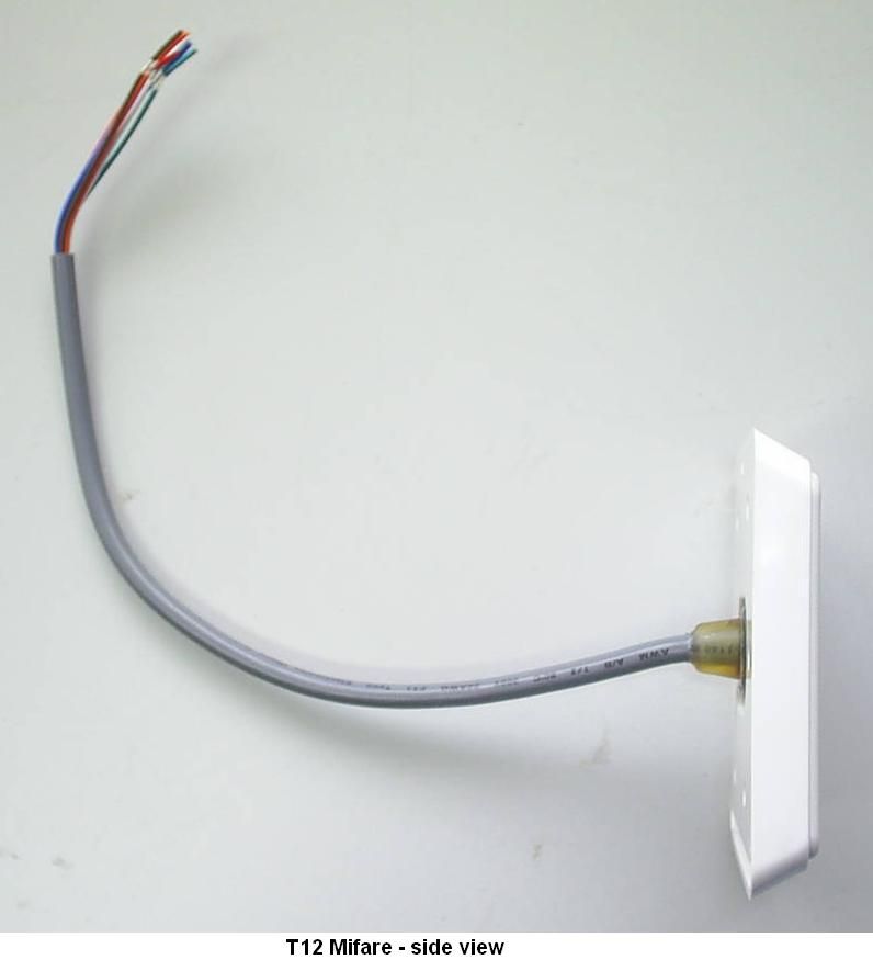
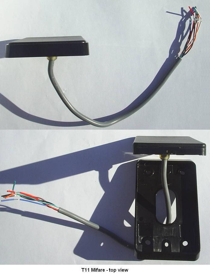
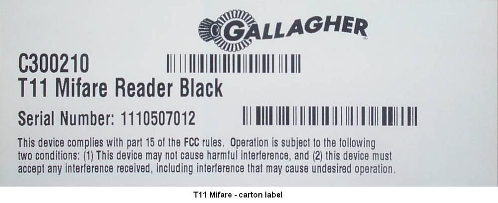
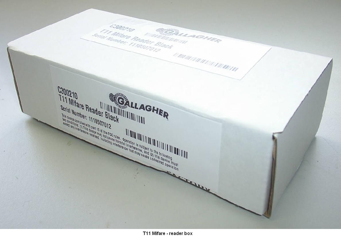
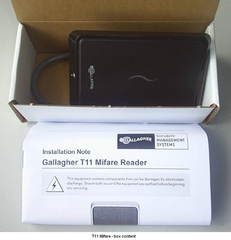
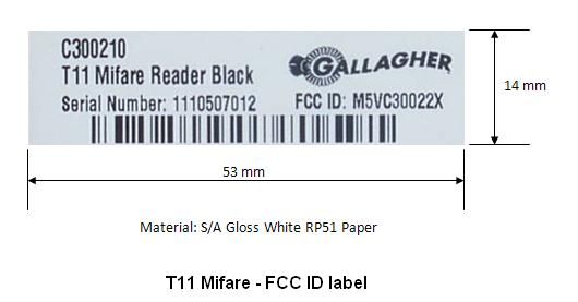
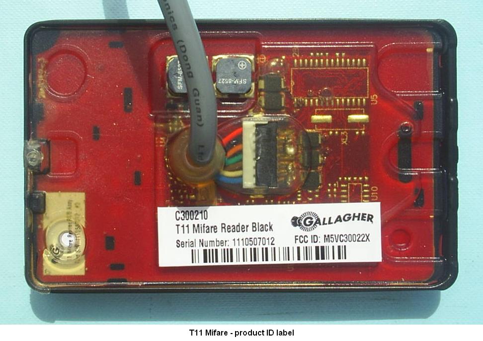
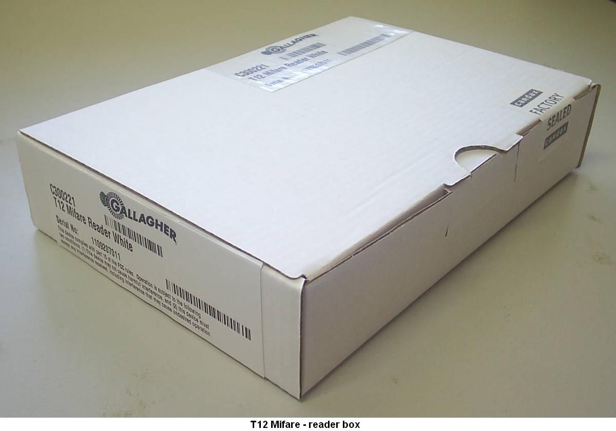
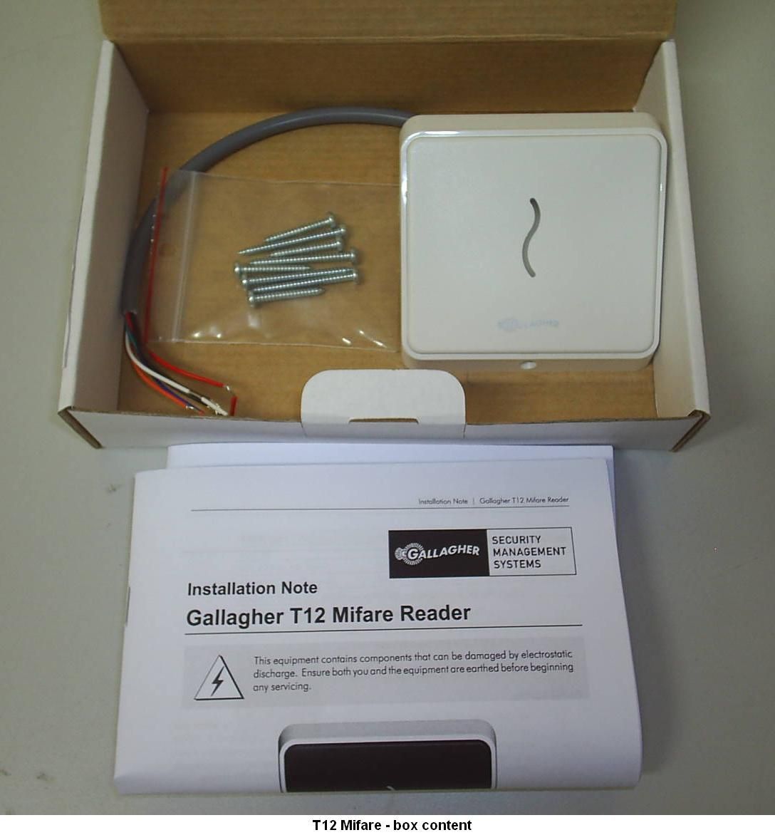
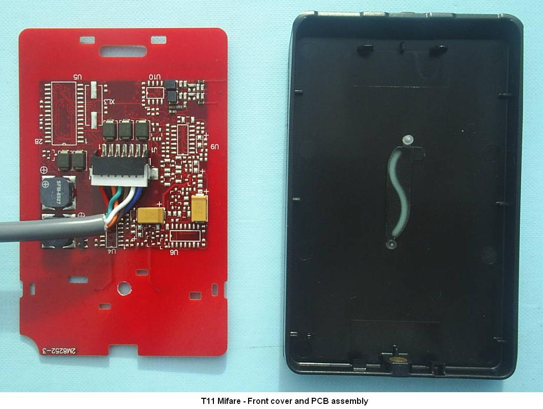
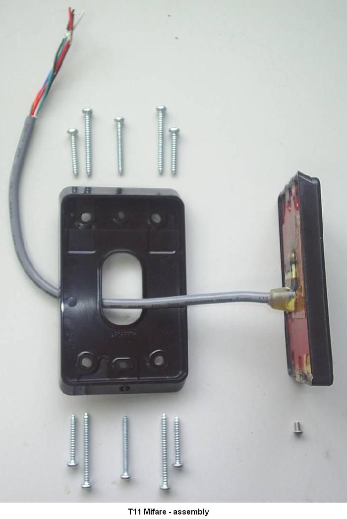
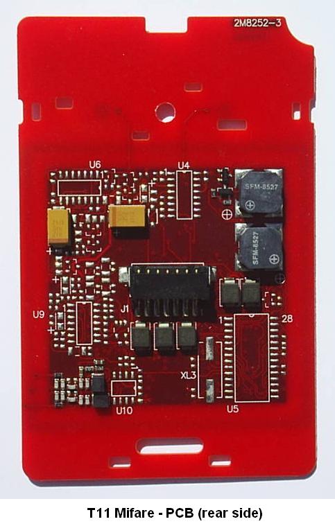
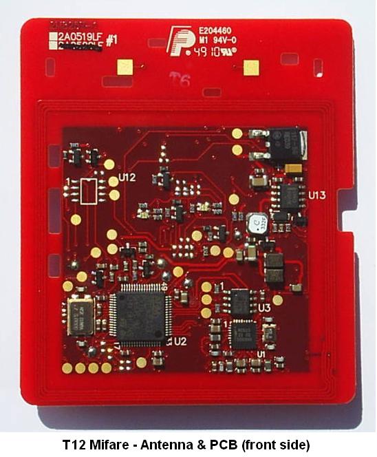
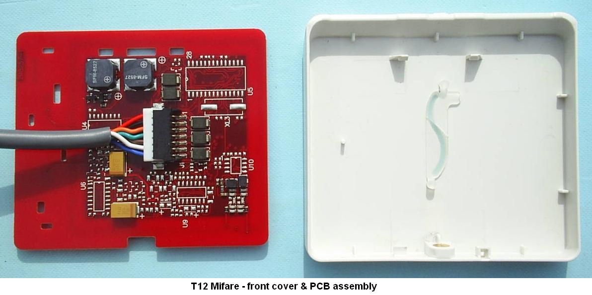
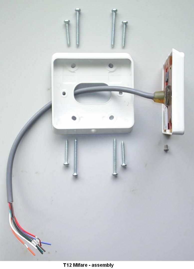
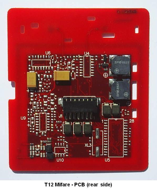
Document Text
Text extracted from the exhibit documents filed with the FCC. Open a document above to read the original.
Users Manual
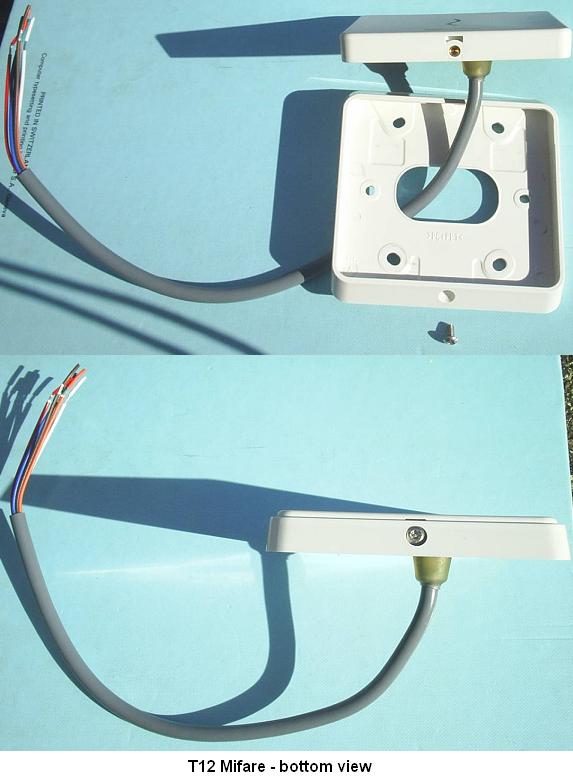
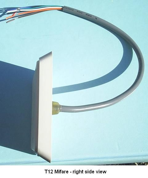
R5 | Part Number: 3E2512 | 1 Installation Note | Gallagher T12 Reader Installation Note Gallagher T12 Reader The Gallagher T12 Reader The Gallagher T12 Reader is a smart card proximity reader. It can be installed as either an entry reader or exit reader. It can be mounted on a BS 4662 British Standard square flush box. The reader can read Mifare DESFire EV1, Mifare Plus and Mifare Classic cards. The Multi Tech variant can also read 125Khz cards. Gallagher T12 Multi Tech Readers only: Using dual technology 125/Mifare cards with Gallagher T12 Multi Tech Readers may cause both card technologies to be read, resulting in double card badges and unusual reader feedback. Gallagher strongly recommends against using dual technology 125/Mifare cards with Gallagher Multi Tech Readers for sites running pre-Command Centre v7.00 software (due for release 2nd half, 2011). From Command Centre v7.00, a site may specify which technology a Multi Tech reader should read off a dual technology card. This equipment contains components that can be damaged by electrostatic discharge. Ensure both you and the equipment are earthed before beginning any servicing. 2 | Part Number: 3E2512 | R5 Installation Note | Gallagher T12 Reader The reader sends information to the Cardax FT Controller and acts upon information sent from the Cardax FT Controller. The reader itself does not make any access decisions. The Gallagher T12 Reader uses the “Cardax IV Reader” communications protocol to communicate with the Cardax FT Controller. Before you begin Shipment Contents Check the shipment contains the following items: 1 x Gallagher T12 Reader facia assembly• 1 x Gallagher T12 Reader base• 1 x M3 Torx Post Security screw• 2 x M3.5 Phillips drive fixing screws• 4 x 25mm No.6 self tapping, pan head, Phillips drive fixing screws• 4 x 40mm No.6 self tapping, pan head, Phillips drive fixing screws• Power Supply The Gallagher T12 Reader is designed to operate over a supply voltage range of 9 - 16Vdc measured at the reader terminals. The operating current draw is dependant on the supply voltage at the reader. For the Standard variant at 12Vdc the current draw is 89mA (standby). During card read, beeper and LED activity, the current will momentarily reach 124mA (peak). For the Multi Tech variant at 12Vdc the current draw is 88mA (standby) and will momentarily reach 140mA (peak). The power source should be linear or a good quality switched-mode power supply. The performance of the reader may be affected by a low quality, noisy power supply. Cabling The Gallagher T12 Reader requires a minimum cable size of 4 core 24 AWG (0.2mm 2 ) stranded security cable. This cable allows the transmission of data (2 wires) and power (2 wires). When using a single cable to carry both power supply and data, both the power supply voltage drop and data requirements must be considered. Although the reader is specified to operate at 9Vdc, for good engineering design it is recommended that the voltage at the reader should be approximately 12Vdc. Examples of approved cables for connecting a single Gallagher T12 Reader to a Controller and power supply, showing maximum cable lengths for each type of cable and the associated circuits are: R5 | Part Number: 3E2512 | 3 Installation Note | Gallagher T12 Reader Manufacturer referenceCable format* Combined power and data in a single cable Data only in a single cable CAT5E4 twisted pair Each 2 x 0.2mm 2 (24 AWG) 100m (330ft)300m (1000ft) SEC4724 x 0.2mm 2 Not twisted pairs (24 AWG) 100m (330ft)250m (800ft) SEC41424 x 0.4mm 2 Not twisted pairs (21 AWG) 150m (500ft)150m (500ft) BELDEN 87232 twisted pair Each 2 x 0.4mm 2 (22 AWG) 100m (330ft)150m (500ft) BELDEN 98422 twisted pair Each 2 x 0.2mm 2 (24 AWG) 100m (330ft)200m (650ft) * The matching of wire sizes to equivalent wire gauges are only approximate. Note: Grounding shielded cable may reduce the obtainable cable length by 25% to 30%. Distance between Proximity Readers The distance separating any two proximity readers must not be less than 200mm (8 inches) in all directions. 200mm When mounting a proximity reader on an internal wall, check that any reader fixed to the other side of the wall is not less than 200mm (8 inches) away. 200mm 4 | Part Number: 3E2512 | R5 Installation Note | Gallagher T12 Reader Installation The Gallagher T12 Reader is designed to be mounted on a standard British electrical flush box, or any solid flat surface. However installation on metal surfaces, particularly those with a large surface area will reduce read range. The extent to which the range is reduced will depend upon the type of metal used. The recommended mounting height for the reader is 1.1m (3.6ft) from the floor level to the centre of the reader device. However this may vary in some countries and you should check local regulations for variations to this height. Ensure the building cable has been run out through the flush box.1. If you are not mounting to a flush box, use the drill template at the back of this installation note as a guide, to drill all five holes. Drill the 13mm (1/2 inch) diameter centre hole (this is the centre hole for which the building cable will exit the mounting surface) and the four fixing holes. Run the building cabling through the reader base.2. Secure the base to the flush box using the two M3.5 screws provided. It is 3. important the base of the reader is flush with and tight against the mounting surface. If you are not mounting to a flush box, secure the base to the mounting surface using the four fixing screws provided. Base Building cable M3.5 screw M3.5 screw Connect the reader tail extending from the facia assembly to the building cable. 4. Connect the wires shown below. Note: Do not cut the ‘Reserved’ wires, as these may be used for future functions. R5 | Part Number: 3E2512 | 5 Installation Note | Gallagher T12 Reader PositiveRed NegativeBlack ReservedOrange ReservedGreen ReservedBrown CDXIV TXWhite CDXIV RXBlue Cardax IV Reader Fit the facia assemb…
Text truncated - open the document above for the full version.
Users Manual
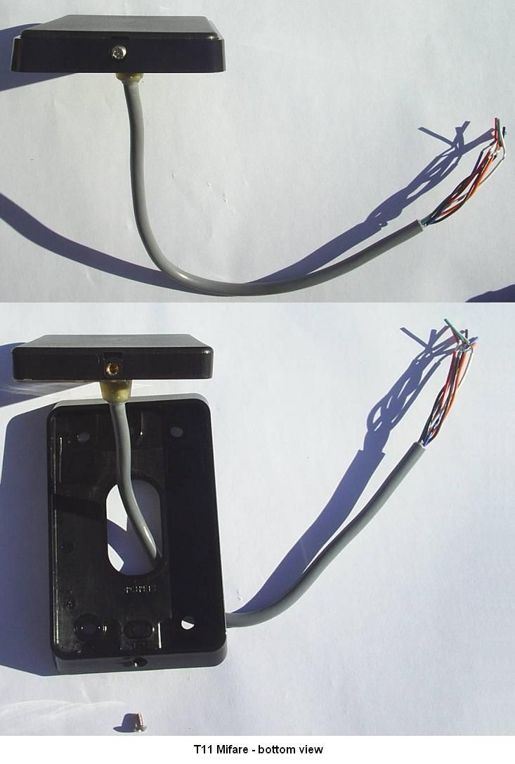
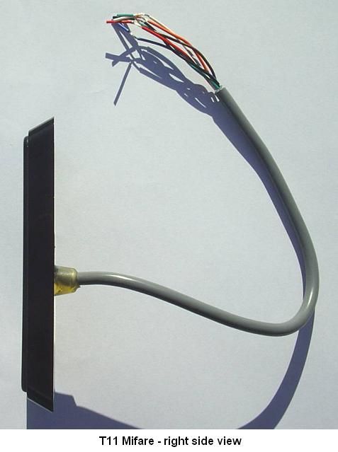
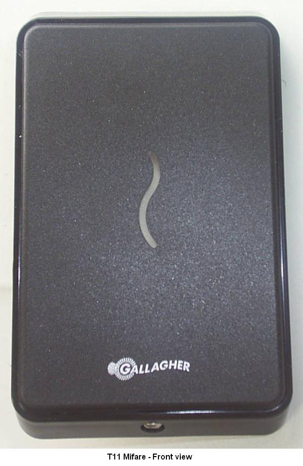
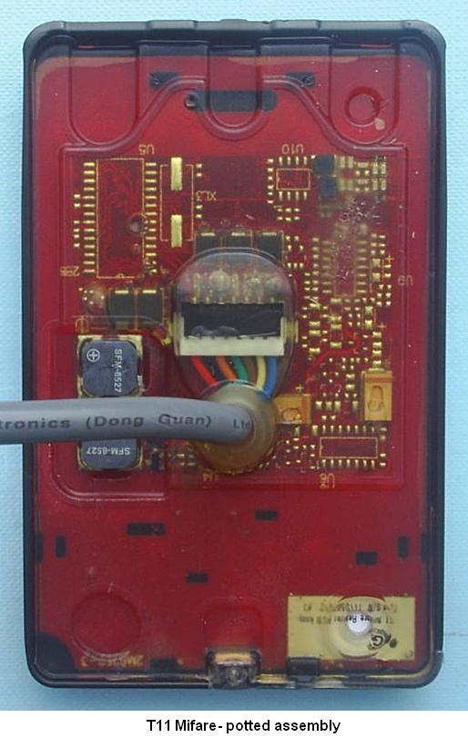
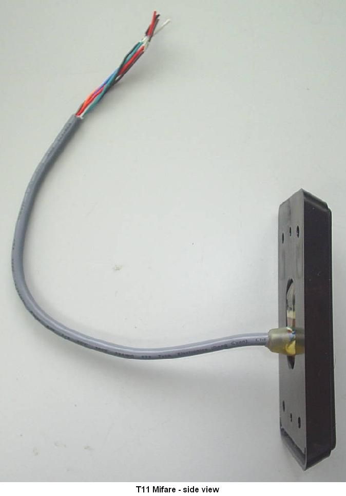
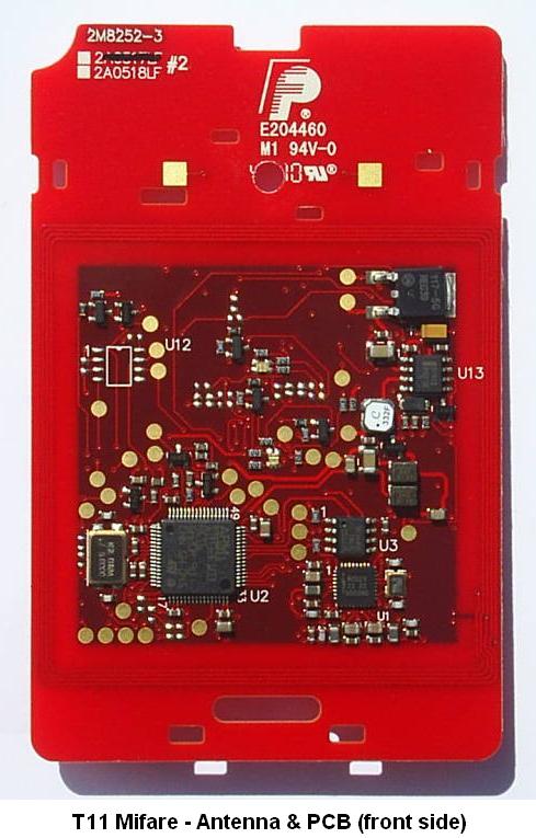
R5 | Part Number: 3E2513 | 1 Installation Note | Gallagher T11 Reader Installation Note Gallagher T11 Reader The Gallagher T11 Reader The Gallagher T11 Reader is a smart card proximity reader. It can be installed as either an entry reader or exit reader. It can be mounted on a vertical, rectangular 50mm x 75mm (2” x 3”) flush box with mounting holes spaced at a nominal 85mm (3.25”). The reader can read Mifare DESFire EV1, Mifare Plus and Mifare Classic cards. The Multi Tech variant can also read 125Khz cards. Gallagher T11 Multi Tech Readers only: Using dual technology 125/Mifare cards with Gallagher T11 Multi Tech Readers may cause both card technologies to be read, resulting in double card badges and unusual reader feedback. Gallagher strongly recommends against using dual technology 125/Mifare cards with Gallagher Multi Tech Readers for sites running pre-Command Centre v7.00 software (due for release 2nd half, 2011). From Command Centre v7.00, a site may specify which technology a Multi Tech reader should read off a dual technology card. This equipment contains components that can be damaged by electrostatic discharge. Ensure both you and the equipment are earthed before beginning any servicing. 2 | Part Number: 3E2513 | R5 Installation Note | Gallagher T11 Reader The reader sends information to the Cardax FT Controller and acts upon information sent from the Cardax FT Controller. The reader itself does not make any access decisions. The Gallagher T11 Reader uses the “Cardax IV Reader” communications protocol to communicate with the Cardax FT Controller. Before you begin Shipment Contents Check the shipment contains the following items: 1 x Gallagher T11 Reader facia assembly• 1 x Gallagher T11 Reader base• 1 x M3 Torx Post Security screw• 2 x 6-32 UNC Phillips drive fixing screws• 4 x 25mm No.6 self tapping, pan head, Phillips drive fixing screws• 4 x 40mm No.6 self tapping, pan head, Phillips drive fixing screws• Power Supply The Gallagher T11 Reader is designed to operate over a supply voltage range of 9 - 16Vdc measured at the reader terminals. The operating current draw is dependant on the supply voltage at the reader. For the Standard variant at 12Vdc the current draw is 89mA (standby). During card read, beeper and LED activity, the current will momentarily reach 124mA (peak). For the Multi Tech variant at 12Vdc the current draw is 88mA (standby) and will momentarily reach 140mA (peak). The power source should be linear or a good quality switched-mode power supply. The performance of the reader may be affected by a low quality, noisy power supply. Cabling The Gallagher T11 Reader requires a minimum cable size of 4 core 24 AWG (0.2mm 2 ) stranded security cable. This cable allows the transmission of data (2 wires) and power (2 wires). When using a single cable to carry both power supply and data, both the power supply voltage drop and data requirements must be considered. Although the reader is specified to operate at 9Vdc, for good engineering design it is recommended that the voltage at the reader should be approximately 12Vdc. Examples of approved cables for connecting a single Gallagher T11 Reader to a Controller and power supply, showing maximum cable lengths for each type of cable and the associated circuits are: R5 | Part Number: 3E2513 | 3 Installation Note | Gallagher T11 Reader Manufacturer referenceCable format* Combined power and data in a single cable Data only in a single cable CAT5E4 twisted pair Each 2 x 0.2mm 2 (24 AWG) 100m (330ft)300m (1000ft) SEC4724 x 0.2mm 2 Not twisted pairs (24 AWG) 100m (330ft)250m (800ft) SEC41424 x 0.4mm 2 Not twisted pairs (21 AWG) 150m (500ft)150m (500ft) BELDEN 87232 twisted pair Each 2 x 0.4mm 2 (22 AWG) 100m (330ft)150m (500ft) BELDEN 98422 twisted pair Each 2 x 0.2mm 2 (24 AWG) 100m (330ft)200m (650ft) * The matching of wire sizes to equivalent wire gauges are only approximate. Note: Grounding shielded cable may reduce the obtainable cable length by 25% to 30%. Distance between Proximity Readers The distance separating any two proximity readers must not be less than 200mm (8 inches) in all directions. 200mm When mounting a proximity reader on an internal wall, check that any reader fixed to the other side of the wall is not less than 200mm (8 inches) away. 200mm 4 | Part Number: 3E2513 | R5 Installation Note | Gallagher T11 Reader Installation The Gallagher T11 Reader is designed to be mounted on vertically orientated electrical flush (gang) boxes, or any solid flat surface. However installation on metal surfaces, particularly those with a large surface area will reduce read range. The extent to which the range is reduced will depend upon the type of metal used. The recommended mounting height for the reader is 1.1m (3.6 ft) from the floor level to the centre of the reader device. However this may vary in some countries and you should check local regulations for variations to this height. Ensure the building cable has been run out through the flush box.1. If you are not mounting to a flush box, use the drill template at the back of this installation note as a guide, to drill all five holes. Drill the 13mm (1/2 inch) diameter centre hole (this is the centre hole for which the building cable will exit the mounting surface) and the four fixing holes. Run the building cabling through the reader base.2. Secure the base to the flush box using the two 6-32 UNC screws provided. It 3. is important the base of the reader is flush with and tight against the mounting surface. If you are not mounting to a flush box, secure the base to the mounting surface using the four fixing screws provided. Base 6-32 UNC screw Building cable 6-32 UNC screw Connect the reader tail extending from the facia assembly to the building cable. 4. Connect the wires shown below. Note: Do not cut the ‘Reserved’ wires, as these may be used for future functions. R5 | Part Number: 3E2513 | 5 Installation Note | Gallagher T11 Reader PositiveRed NegativeBlack ReservedOrang…
Text truncated - open the document above for the full version.
Cover Letter(s)
Gallagher Group Ltd 181 Kahikatea Drive Private Bag 3026 Hamilton, New Zealand Tel: +64-7-838-9800 Fax: +64-7-838-9801 Email: [email protected] www.gallaghergroup.co.nz Companies Gallagher Group Ltd – NZ Sunplas Engineering (82) Ltd – NZ Gallagher Security (int) Ltd – NZ Gallagher Power Fence (SA) Pty – Sth Africa Gallagher Security (UK) Ltd – UK Gallagher Security (USA) Inc – USA Franklin Machinery – New Zealand PEC Pumps PEC Fuel Pumps Ltd Cardax (International) Ltd Gallagher Finance & Management Ltd Gallagher IT Solutions Ltd Reach Global Ltd Associate Companies Gallagher Europe Veldman & Djikstra Gallagher Australia Pty Ltd – Australia Gallagher Insultimber – Australia Gallagher Power Fence Inc – USA Gallagher Power Fencing Systems Inc – Canada Gallagher Power Fence (IRL) Ltd – Ireland Ibex Gallagher – India A/S Poda Hegn – Denmark NZ Producciones S.A – Argentina International Scales Pty Ltd - Australia August 12, 2010 To Whom It May Concern: I hereby appoint Menardo Lazaro to sign letters and applications for any filings with regulatory agencies on our behalf, and to receive and exchange data between our company, the agents company and the agency in connection with certification for any products that our company owns or manufactures. Sincerely, Tony Smith Technical Development Manager Gallagher Group Ltd.
Cover Letter(s)
Gallagher Group Ltd 181 Kahikatea Drive Private Bag 3026 Hamilton, New Zealand Tel: +64-7-838-9800 Fax: +64-7-838-9801 Email: [email protected] www.gallaghergroup.co.nz Companies Gallagher Group Ltd – NZ Sunplas Engineering (82) Ltd – NZ Gallagher Security (int) Ltd – NZ Gallagher Power Fence (SA) Pty – Sth Africa Gallagher Security (UK) Ltd – UK Gallagher Security (USA) Inc – USA Franklin Machinery – New Zealand PEC Pumps PEC Fuel Pumps Ltd Cardax (International) Ltd Gallagher Finance & Management Ltd Gallagher IT Solutions Ltd Reach Global Ltd Associate Companies Gallagher Europe Veldman & Djikstra Gallagher Australia Pty Ltd – Australia Gallagher Insultimber – Australia Gallagher Power Fence Inc – USA Gallagher Power Fencing Systems Inc – Canada Gallagher Power Fence (IRL) Ltd – Ireland Ibex Gallagher – India A/S Poda Hegn – Denmark NZ Producciones S.A – Argentina International Scales Pty Ltd - Australia Federal Communication Commission Equipment Authorization Division, Application Processing Branch 7435 Oakland Mills Road Columbia, MD 21048 March 31, 2011 TO WHOM IT MAY CONCERN Pursuant to Paragraphs §0.457 and 0.459 of the Commission’s Rules (47 C.F.R.) and Section §552(b)(4) of the Freedom of Information Act, Gallagher Group Ltd requests confidentiality for the following products: FCC ID Number Product Title/Model M5VC30022X T11 Mifare Reader and T12 Mifare Reader For the product stated above, we request that the following information be held confidential: 1) Electrical Schematics of the Circuitry 2) Block Diagram 3) Operational Description No other items submitted as part of the equipment authorisation filing process are deemed confidential. The above exhibits contain Gallagher Group Ltd trade secrets and proprietary information that could be of benefit to our competitors regarding the design of our Prox Reader. This material is not customarily available to the general public and we request that it be withheld from public inspection. If you have any questions, please feel free to contact me at the address shown below. Sincerely, Menardo Lazaro Compliance Engineer Gallagher Group Ltd
Test Report
____________________________________________________________________________________________________________________________________________________________________________ Page 1 of 20 Test Report No 110313.1 25 March 2011. This report may not be reproduced except in full. EMC Technologies (NZ) Ltd PO Box 68-307 Newton, Auckland Phone 09 360 0862 Fax 09 360 0861 E-Mail Address: [email protected] Web Site: www.emctech.com.au TEST REPORT Gallagher T12 Flush MiFare Card Reader tested to 47 Code of Federal Regulations Part 15 - Radio Frequency Devices Subpart C – Intentional Radiators Section 15.225 Operation within the band 13.110 -14.010 MHz for Gallagher Group Ltd This Test Report is issued with the authority of: ________________________________________ Andrew Cutler- General Manager ____________________________________________________________________________________________________________________________________________________________________________ Page 2 of 20 Test Report No 110313.1 25 March 2011. This report may not be reproduced except in full. Table of Contents 1. STATEMENT OF COMPLIANCE 3 2. RESULTS SUMMARY 3 3. INTRODUCTION 4 4. CLIENT INFORMATION 4 5. DESCRIPTION OF TEST SAMPLE 4 6. SETUPS AND PROCEDURES 5 7. TEST EQUIPMENT USED 15 8. ACCREDITATIONS 15 9. PHOTOGRAPHS 16 ____________________________________________________________________________________________________________________________________________________________________________ Page 3 of 20 Test Report No 110313.1 25 March 2011. This report may not be reproduced except in full. 1. STATEMENT OF COMPLIANCE The Gallagher T12 Flush MiFare Card Reader complies with FCC Part 15 Subpart C Section 15.225 as an Intentional Radiator when the methods as described in ANSI C63.4 - 2003 are applied. 2. RESULTS SUMMARY The results from testing are summarised in the following table: Clause Parameter Result 15.201 Equipment authorisation requirement Certification required. 15.203 Antenna requirement Complies. Antennas internal to the device. 15.204 External PA and antenna modifications Not applicable. No external devices. 15.205 Restricted bands of operation Complies. Device transmits on 13.560 MHz. 15.207 Conducted limits Complies. 15.209 Radiated emission limits - Spurious emissions <30 MHz Complies with a 31.8 dB margin at 27.120 MHz 15.209 Radiated emission limits – Spurious emissions >30 MHz Complies with a 3.9 dB margin at 40.680 MHz (Vertical). 15.225 Radiated emission limits - Fundamental Complies with a 51.5 dB margin at 13.560 MHz. 15.225 Frequency stability Complies ____________________________________________________________________________________________________________________________________________________________________________ Page 4 of 20 Test Report No 110313.1 25 March 2011. This report may not be reproduced except in full. 3. INTRODUCTION This report describes the tests and measurements performed for the purpose of determining compliance with the specification. The client selected the test sample. This report relates only to the sample tested. This report contains no corrections or erasures. Measurement uncertainties with statistical confidence intervals of 95% are shown below test results. Both Class A and Class B uncertainties have been accounted for, as well as influence uncertainties where appropriate. 4. CLIENT INFORMATION Company Name Gallagher Group Ltd Address Kahikatea Drive City Hamilton Country New Zealand Contact Mr Brian Rose 5. DESCRIPTION OF TEST SAMPLE Brand Name Gallagher Model Number T12 Product Flush MiFare Card Reader Manufacturer Gallagher Group Ltd Country of Origin New Zealand Serial Number 1109207011 FCC ID M5VC30022X ____________________________________________________________________________________________________________________________________________________________________________ Page 5 of 20 Test Report No 110313.1 25 March 2011. This report may not be reproduced except in full. 6. SETUPS AND PROCEDURES Standard The sample was tested in accordance with 47 CFR Part 15 Subpart C. Methods and Procedures The measurement methods and procedures as described in ANSI C63.4 - 2003 were used. Section 15.201: Equipment authorisation requirement Certification as detailed in Subpart J of Part 2 is required for this device. Section 15.203: Antenna requirement This device has an internal antenna for a 13.560 MHz transmitter. Result: Complies. Section 15.204: External radio frequency power amplifiers and antenna modifications It is not possible to attach an external power amplifier to this transmitter. Result: Complies. Section 15.205: Restricted bands of operation The transmitter transmits on 13.560 MHz. This device would therefore fall into the band 13.110 – 14.010 MHz that is covered by Section 15.225. Result: Complies. ____________________________________________________________________________________________________________________________________________________________________________ Page 6 of 20 Test Report No 110313.1 25 March 2011. This report may not be reproduced except in full. Section 15.207: Conducted emissions testing Conducted Emissions testing was carried out over the frequency range of 150 kHz to 30 MHz which was carried out at the laboratory’s MacKelvie Street premises in a 2.4 m x 2.4 m x 2.4 m screened room Testing was carried out using a representative AC power supply system that was powered at 120 Vac which supplied 12 Vdc to a GBUS URI device which in turn powered the Card Reader also at 12 Vdc. The device operates on 13.560 MHz. Testing was carried out with the 13.560 MHz transmitter operating with the standard antenna attached and with this antenna removed and replaced with a dummy load. The device is deemed to comply providing it complies when the test is carried out with a dummy load attached and the overall emission signature for the product remains similar with no additional emissions being detected. This is the case with this device. The device was placed…
Text truncated - open the document above for the full version.
Test Setup Photos
Page 1 of 3 T12 Mifare - Test Setup Photos Page 2 of 3 Page 3 of 3
Contact Information
Applicant
Tony Smith(Hardware Development Manager)
Technical Contact
Gallagher Group Ltd.Menardo Lazaro
[email protected]+6478389800
181 Kahikatea Drive, Melville · Hamilton · New Zealand
Test Firm
EMC Technologies NZ Ltd.Andrew Cutler
Technical Specifications
| # | Rule Parts | Frequency Range | Power Output |
|---|---|---|---|
| 1 | 15C | 13.56 MHz - 13.56 MHz | - |
Other Applications from Gallagher Group Ltd
M5VG03307
Apr 24, 2026Handheld EID Tag Reader HR0
Equipment Class
DCD - Part 15 Low Power Transmitter Below 1705 kHz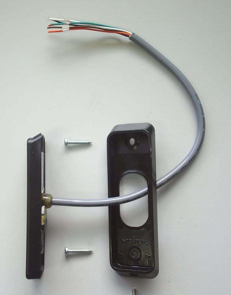
M5VC30040XB
Mar 28, 2023Prox Readers T10 Mifare
Equipment Class
DXX - Part 15 Low Power Communication Device Transmitter
M5VC30047XB
Feb 16, 2022Prox Readers T15 Mifare
Equipment Class
DXT - Part 15 Low Power Transceiver, Rx Verified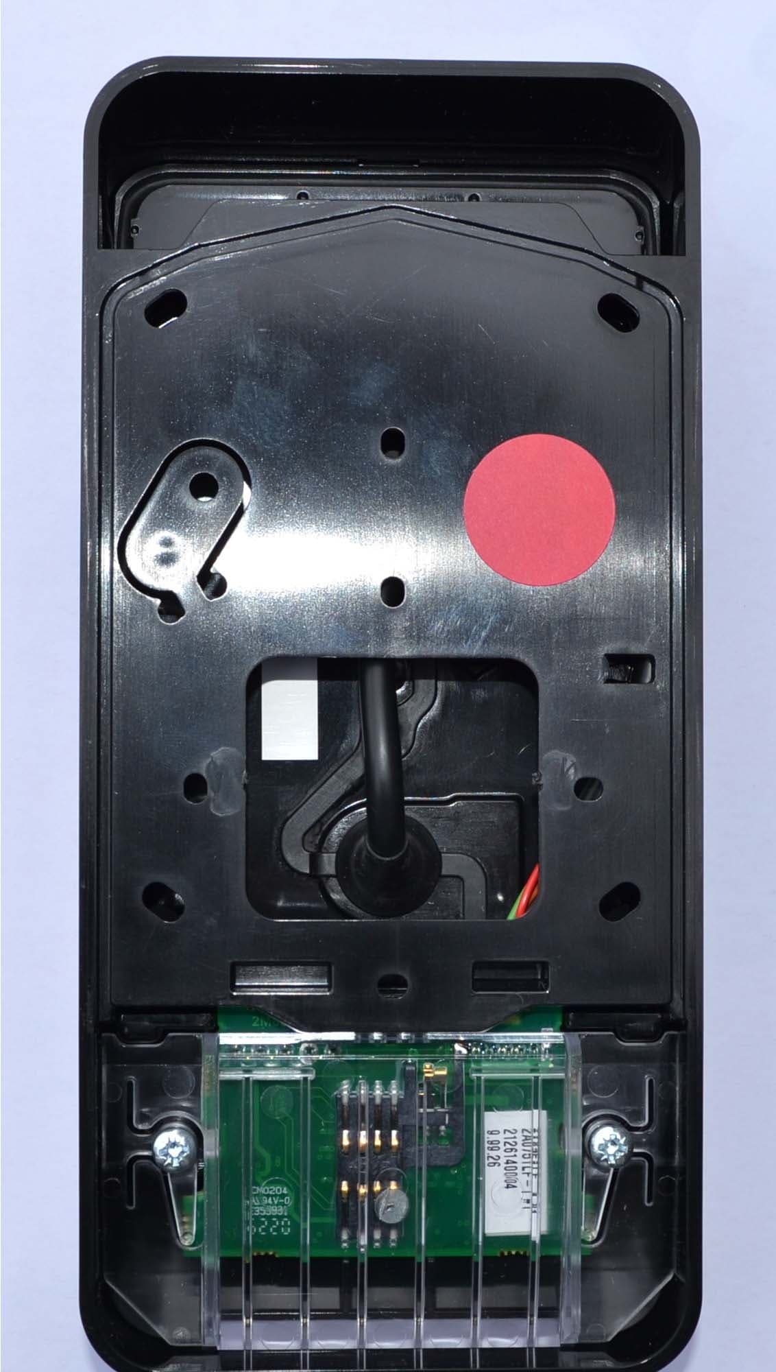
M5VC30550X
Jul 28, 2021Prox Readers T21 PIV
Equipment Class
DXT - Part 15 Low Power Transceiver, Rx Verified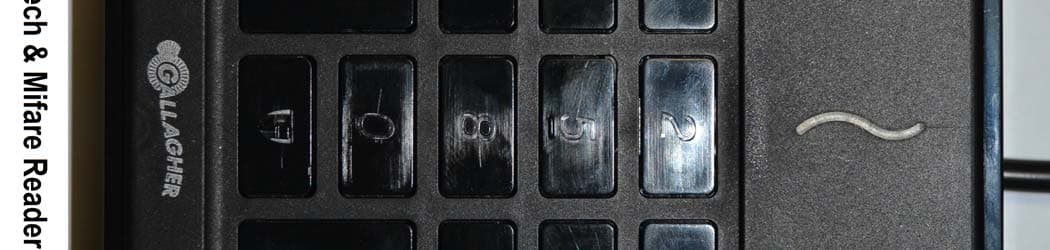
M5VC30049X
Aug 19, 2020Prox Readers T30
Equipment Class
DXT - Part 15 Low Power Transceiver, Rx Verified