M5VG03301Smart Reader HR3
Gallagher Group Ltd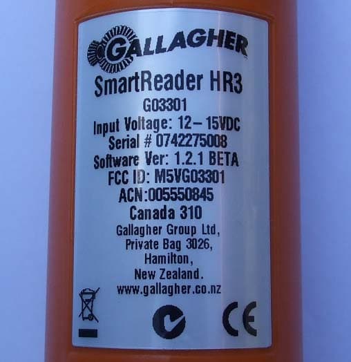
Click to zoom
Application Details
- Equipment Class
- DXT - Part 15 Low Power Transceiver, Rx Verified
- Date of Grant
- Jan 30, 2008
- Application Purpose
- Original Equipment
- Date of Application
- Jan 24, 2008
- Equipment Note
- Smart Reader HR3
- Frequency Range
- 0.13420000 - 0.13420000
- Company
- Gallagher Group Ltd
- Country
- New Zealand
Documents & Files
Document Text
Text extracted from the exhibit documents filed with the FCC. Open a document above to read the original.
Users Manual
SmartReader HR3 User Manual PUBLISHED BY Gallagher Group Limited Kahikatea Drive, Private Bag 3026 Hamilton, New Zealand Copyright© Gallagher Group Limited 2007. All rights reserved. Patents Pending. Gallagher SmartReader HR3 User Manual 3E0820 - Edition 1 - November 2007 DISCLAIMER Whilst every effort has been made to ensure accuracy, neither Gallagher Group Limited nor any employee of the company, shall be liable on any ground whatsoever to any party in respect of decisions or actions they may make as a result of using this information. In accordance with the Gallagher policy of continuing development, design and specifi cations are subject to change without notice. Developed and manufactured by Gallagher Group Limited, an ISO 9001:2000 Certifi ed Supplier. 3 Table of Contents Overview 5 Tag types read ........................................................................................... 5 Care and Maintenance .............................................................................. 5 MyScale Pro ............................................................................................... 6 Configurator Software ............................................................................. 6 User information 7 Kit Contents ............................................................................................... 7 Terminology ............................................................................................... 7 SmartReader HR 3 features ....................................................................... 9 Power options ......................................................................................... 14 Setting up the SmartReader HR 3 ........................................................... 17 Using the SmartReader .......................................................................... 24 Accessories 25 USB Bluetooth Adaptor .......................................................................... 25 Specifications 25 Waste Electrical and Electronic Equipment .......................................... 25 Approvals and Standards 26 5 Overview The Gallagher SmartReader HR3 is a Bluetooth enabled hand held Electronic ID reader which allows the user to read and store ISO animal Electronic ID tags. The Gallagher SmartReader HR3 contains internal memory and internal rechargeable batteries. The Gallagher SmartReader HR 3 has two modes of operation: Memory Mode• - The captured Electronic ID tag data is stored in the SmartReader in sessions until it is transferred to computer using the MyScale Pro software, and is also immediately sent out the Serial port (via cable) to a Scale or data logging device. Non-Memory Mode• - The captured Electronic ID tag data is immediately sent out the Serial port (via Bluetooth or cable) to a Scale or data logging device. Tag types read The Gallagher SmartReader HR3 enables you to read both HDX (Half Duplex) and FDX-B (Full Duplex-B) Electronic ID tags. Care and Maintenance The SmartReader HR3 is a tough and reliable product designed for use in typical livestock environments. However, proper care and maintenance can extend the SmartReader’s life. Listed below are guidelines for keeping the SmartReader in good condition. For optimal battery life, Gallagher recommends that you store the SmartReader in a • cool, dry area (15 to 25 ° Celsius) out of direct sunlight. After use, clean the SmartReader with a damp cloth. Take care not to scratch the • display. 5 6 Recharge the batteries after use and before storing for extended periods.• MyScale Pro The MyScale Pro software enables you to transfer Electronic ID tag numbers stored in the SmartReader HR3 memory to a computer. With MyScale Pro you can perform the following functions: Download sessions from the SmartReader.• NOTE: Sessions on the SmartReader are automatically deleted off the reader after downloading. Change session fi le names.• View and Edit sessions.• Print sessions.• For further details refer to the MyScale Pro for SmartReaders User Manual. * Configurator software The Confi gurator is a software program provided with the SmartReader. It is used to alter user settings on the SmartReader. The Confi gurator is for advanced users and should be used with care as altering settings affects the operation of the SmartReader. The Confi gurator software is automatically installed with the MyScale Pro software or can be installed separately. For further details refer to the SmartReader HR 3 Confi gurator User Manual. * * How these documents are accessible to you depends on what option you selected when installing MyScale Pro. Either: double-click the shortcut on your desktop, or• from the • Start menu, select All Programs > MyScale Note: Adobe Acrobat is needed to be able to read these documents. If not already installed on your PC, it is available on the installation CD (AdbeRdr810_en_US.exe). 7 User information Kit Contents The Gallagher SmartReader HR3 box contains: Gallagher SmartReader HR• 3 (Bluetooth enabled) Reader to RS232 (weighscale comms/power) cable• RS232 plug (power socket) to 12v battery cable• Bluetooth RS232 adaptor with short extension cable• USB to RS232 cable• Instruction manual• 15 V DC battery charger (100-240 VAC)• MyScale Pro CD• Terminology The following are terms and abbreviations used throughout this manual: BluetoothBluetooth is a short-range radio communication technology. It enables data to be transmitted wirelessly over short distances. Bluetooth module Mounted in SmartReader handle. Sends Electronic ID tag data to the Bluetooth device (RS232 or USB). Bluetooth to RS232 device Connected to the Serial port of the Scale and receives the tag data sent by the SmartReader. Receives Bluetooth communications from the SmartReader and converts the received information into RS232 format so it can be passed onto a Scale. The Bluetooth module in the SmartReader and the Bluetooth device are paired. 8 Bluetooth to USB device Connected to the USB port of a…
Text truncated - open the document above for the full version.
Cover Letter(s)
Non-Conformities FCC ID : M5VG03301 (CKC CS Ref # E07-000110-FCC-01) The items listed below represent requests for information following review of this application for certification under United S tates (FCC) regulations. Further question may arise pending review of responses to these items. OK # Non-Conformity or Co mment Submitted Response Respondent / Date of Response X 1 The confidentiality letter provided includes a request for confidentiality for internal photos. This request must be justified in order to be considered legitimate; proper justification includes such items as (for example) this item is normally potted and any attempt to remove the potting material would destroy the unit. Please provide a revised confidentiality letter either providing proper justification for the request or removing the internal photos from the confidentiality request. Updated confidentiality letter provided. 11/15/07 Gallagher X 2 The operational description, schematics and block diagrams provided appear to be only from the 134kHz transmitter within the equipment. Please provide updated or additional documents containing the necessary information required by 2.1033. Additional Items provided. 1/25/08 Sonoar / Gallagher X 3 The information provided at the time of filing did not include the BT portion of the equipment. Please confirm the following changes to the application form: a) device is composite equipment, b) composite FCC ID is M5VG03301 and is presently pending c) equipment specifications are frequency range 2402-2480MHz, output power (see below), rule part 15C, equipment class DSS. Please co nfirm these changes are correct. Approved 1/10/08 Gallagher x 4 The power output measured in the test report does not clearly indicate if the values have been corrected for antenna gain. The requirements of 15.247(b) are for conducted output power. It appe ars that the standard falloff of 11.8 dB has been used to calculated the c onducted levels for the transmitter output – this method is inaccurate since it does not take into account the antenna gain for comparison of the conducted output power limit (see annex of DA00-705 for further details). Please clarify the method used provide conducted output power measurements for comparison to the limit. Please update the test report as necessary. Please note that the rated output power listed in the test report on page 5 indicates 0dBm output power, while the measurements indicate -11dBm. This large discrepancy is (in part) the source of the question (see below). Updated test report provided 1/10/08 Gallagher X 5 The test setup photos indicate testing with the unit lying on a wooden table. The FCC is concerned about the possible attenuation of field strength levels with measurements above 1 GHz esp ecially for 2.4GHz devices. Please confirm that this test setup indicates the highest field strength measurements and is equivalent to measurement of the emissions when in free-space (such as using a non-conductive support with dialectric constant near 1.0, for example Styrofoam). Updated test report provided. 1/10/08 Gallagher X 6 Due to the portable nature of th is equipment, please confirm that the configuration used in representative of the worst case emissions from three orthogonal polarities of the equipment as required for preliminary investigations by ANSI C63.4. Updated test report provided 1/10/08 Gallagher X 7 The horn antenna listed in the equipment list on page 25 does not appear to cover the frequency range necessary for measurement of spurious emissions up to 25GHz as required by 15.33. Please explain and update test report as necessary. Updated test report provided. 1/10/08 Gallagher X 8 Voltage variations required by 15.31(e) do not appear to have been performed according to the test report. Please update test report as necessary. The reader is normally powered by batteries and was tested with a fully charged battery. Gallagher 11/15/07 X 9 Please provide an updated users manua l incorporating the statement required by 15.21. Updated users manual provided. Gallagher 11/15/07 X 10 Please provide an updated label or manual as appropriate with labeling requirements in accordance with 15 .19. Please review FCC labelling guidelines at http://www.fcc.gov/oet/ea/Labelling_Guid elines_Parts_15_and_18_final.pdf Updated users manual provided. Gallagher 11/15/07 X 11 for compliance under 15.247(d), spurious emissions the actual value of the emissions from the measurements. Pleas e update test report as necessary. Updated test report provided Gallagher 1/10/08
Cover Letter(s)
Gallagher Group Ltd 181 Kahikatea Drive Private Bag 3026 Hamilton, New Zealand Tel: +64-7-838-9800 Fax: +64-7-838-9801 Email: [email protected] www.gallaghergroup.co.nz Companies Gallagher Group Ltd – NZ Sunplas Engineering (82) Ltd – NZ Gallagher Security (int) Ltd – NZ Gallagher Power Fence (SA) Pty – Sth Africa Gallagher Security (UK) Ltd – UK Gallagher Security (USA) Inc – USA Franklin Machinery – New Zealand PEC Pumps PEC Fuel Pumps Ltd Cardax (International) Ltd Gallagher Finance & Management Ltd Gallagher IT Solutions Ltd Reach Global Ltd Associate Companies Gallagher Europe Veldman & Djikstra Gallagher Australia Pty Ltd – Australia Gallagher Insultimber – Australia Gallagher Power Fence Inc – USA Gallagher Power Fencing Systems Inc – Canada Gallagher Power Fence (IRL) Ltd – Ireland Ibex Gallagher – India A/S Poda Hegn – Denmark NZ Producciones S.A – Argentina International Scales Pty Ltd - Australia Federal Communication Commission Equipment Authorization Division, Application Processing Branch 7435 Oakland Mills Road Columbia, MD 21048 November 19, 2007 TO WHOM IT MAY CONCERN Pursuant to Paragraphs §0.457 and 0.459 of the Commission’s Rules (47 C.F.R.) and Section §552(b)(4) of the Freedom of Information Act, Gallagher Group Ltd requests confidentiality for the following products: FCC ID Number Product Title/Model M5VG03301 Smart Reader HR3 For the product stated above, we request that the following information be held confidential: 1) Electrical Schematics of the Circuitry 2) Block Diagram 3) Operational Description No other items submitted as part of the equipment authorisation filing process are deemed confidential. The above exhibits contain Gallagher Group Ltd trade secrets and proprietary information that could be of benefit to our competitors regarding the design of our reader. This material is not customarily available to the general public and we request that it be withheld from public inspection. If you have any questions, please feel free to contact me at the address shown below. Sincerely, Paul Young Compliance Engineer Gallagher Group Ltd Kahikatea Drive Hamilton New Zealand Phone: 64 7 838-9874 Fax: 64 7 838-9801
External Photos
EXTERNAL PHOTOS Product Photo Left Side View Right Side View Top View Bottom View Front View Label
ID Label/Location Info
Top View Bottom View Front View Label
Internal Photos
INTERNAL PHOTOS Main PCB - Top Side Main PCB - Bottom Side Logic PCB - Top Side Logic PCB – Bottom Side LCD Interfacing PCB - Top Side LCD Interfacing PCB – Bottom Side Buzzer PCB - Top Side Buzzer PCB - Bottom Side Trigger PCB - Top Side Trigger PCB - Bottom Side Antenna PCB – Top Side Antenna PCB – Bottom Side Internal Assembly
Operational Description
Operation Description Summary The Hand held Reader (part number G03301) is a proximity reader that operates with a fundamental frequency of 134.2 kHz. A microprocessor controls all the operation of the reader. The reader uses an internal antenna to read Radio Frequency Identification (RFID) tags off an animal. The reader can read ISO11784/ISO11785 Full Duplex (FDX) and Half Duplex (HDX) tags or transponders. Eight cells of Nickel Metal Hydride (NiMH) batteries power the reader. The batteries are charged with an external mains powered charger. While the charger is connected, the reader will not read tags. The reader can also run off an external battery. An LCD displays user information, eg. the number of tags read, battery life, diagnostics, etc. A LED, a vibrator and two buzzers indicates a valid tag read. Connectivity to the reader is via RS232 or Bluetooth. Block Description Onboard Microprocessor All functions are controlled by the onboard Renesas R5F21258 microprocessor. The functions include user inputs such as the button, display such as the LCD, and communications such as RS232 and wireless. The microprocessor clock is driven by the oscillator. Power Management The external and battery power supply to the reader is controlled by the power management circuitry. This protects the reader and batteries from over or under voltage conditions. Power Supply Power from the batteries power the 3.3V 500kHz Switch Mode Power Supply (SMPS), the transmit circuitry, the Buzzers, and the linear 5V (powers the FDX and HDX receive circuitry). The SMPS supply power to the microprocessor, LCD module, Bluetooth module, LED and vibrator. Oscillator The oscillator consists of the 17.1776MHz crystal which is driven by a 74HC04 single gate inverter. The output of the inverter is divided down to 3.3V by a voltage divider and fed to the microprocessor. The output from the inverter also feeds into a 15-stage counter to generate 134.2 kHz square wave for the transmitter. Button There is one trigger button for user input. Buzzers Two buzzers are controlled by the microprocessor for an audible indication of a valid tag read Half Duplex (HDX) Receive HDX tags respond during the off cycle. During the transmit cycle, the HDX tag is charged up by the antenna. The HDX then replies during the off cycle. The signal from the antenna feeds into the SA604A Frequency Modulation amplifier and demodulator system which outputs the HDX data to the microprocessor. Full Duplex (FDX) Receive FDX tags respond during the activation/transmit cycle. The antenna signal feeds into a network of rectifiers and filters (passive and active) to extract the FDX data. The FDX data is then feed into the microprocessor for processing. Transmit The activation cycle is generated as follows: The microprocessor outputs a signal to the 74HC04 single gate inverter, which feeds into the TC4428 FET drivers. The FET drivers drive the Bridge configured FETs that are loaded with the transmit transformer. The output of the transmit transformer is connected with the antenna and capacitors to form a series LC resonant circuit. Read Range Control To control the read (long or short range) performance of the reader, the LC circuit’s performance is controlled by the microprocessor. It can ‘switched in or out’ a capacitor in the LC circuit to reduce the read performance. EEPROM I2C bus protocol 24LC512 EEPROM is used. Some configuration info and tag data is stored in the EEPROM. Wireless There is a Bluetooth module to give the reader Bluetooth connectivity. LCD Module A LCD module displays the tag count, tag number, battery condition and the connectivity of the Bluetooth. The LCD module is controlled by the microprocessor via the I2C bus. RS232 Communications to other devices are via the MAX3232 RS232 converter chip. The RS232 ports are protected by Transient Voltage Suppressors (TVS). Read LED A super bright red LED controlled by the microprocessor provides visual indication of transmission and valid tag reads. Vibrator A 3.3V vibrating motor is controlled by the microprocessor to indicate a valid tag read.
Operational Description
apm1842 Bluetooth Class2 Module Preliminary Data Sheet Page 1 of 11 apm1842 Bluetooth Class2 Module General Description This compact Bluetooth™ class2 PCB module combines a 2.4 GHz radio processor, regulator, crystal, matching network, on-board antenna and flash memory into a single PCB module with a small form factor of 14mm by 32mm by 2.45mm. A jumper is used to select the on-board antenna or an external antenna. This PCB module provides internal Flash allowing loading specified profiles and customized application software. The module also supports the deep sleep mode to reduce power consumption. Features y Small form factor module. PCB LGA package with a compact size of 14mm by 32mm by 2.45mm. y Low power consumption. y Integrating Bluetooth chip, matching network, antenna, crystal, 4Mbit flash memory and LDO on a single module. y Provide total solution for Bluetooth and WLAN co-existence technology. y Support multiple reference clock frequencies for GSM/GPRS and CDMA cellular applications. y Compliant with Bluetooth specification V1.2. y Support UART and USB 2.0 interfaces. y PCM audio CODEC interface supports both master and slave mode operation. y Support firmware upgrade. Applications y Portable Devices: Cellular phones, headsets, PDAs, palmtops. y Computer Peripheral: PCs, notebooks, printers. y Consumer Electronics: MP3 players, digital cameras, joysticks. y Automotive phone kits, Bluetooth tire pressure sensors, Barcode scanners. Functional Block Diagram apm1842 Bluetooth Class2 Module Preliminary Data Sheet Page 2 of 11 TABLE OF CONTENTS 1 Pin Descriptions 3 1-1 Pin Assignment (Top view) 3 1-2 Pin Definition 3 2 System Specifications 5 3 Electrical Characteristics 5 4 apm1842 Bluetooth System Stacks 8 5 WLAN Coexistence Technology 9 6 Mounting Guide for Antenna Performance 10 7 Mechanical Drawing 11 8 Contact Information 11 apm1842 Bluetooth Class2 Module Preliminary Data Sheet Page 3 of 11 1 Pin Descriptions 1-1 Pin Assignment (Top view) 1-2 Pin Definition Pin # Pin Name Pad Type Description 1 RF_I/O Analog RF signal input into the receiver or output from the transmitter. 2-8 GND Ground Ground connections. 9 VDD_USB Power Positive supply for USB interface. 10 VDD_OUT Power 3.3V output power from internal regulator 11 EXT_WAKE CMOS input Wake up signal from host. 12 HOST_WAKEUP CMOS output Wake up signal to host. 13 UART_TXD CMOS output UART transmit data. 14 UART_RTS CMOS output UART flow control ready to send. GND 4 USB_DPLUS_PULLUP 17 UART_RTS 14 VDD_IN 20 HOST_WAKE 12 GND 24 PCM_CLK 31 PCM_SY NC 29 VDD_USB 9 UART_CTS 15 GND 6 PIO[1] 35 GND 27 NC(CLK32K_OUT) 26 PCM_IN 33 RF I/O 1 GND 36 apm1842 EN 21 GND 23 USB_DMNS 18 NC(CLK_IN) 38 PIO[0] 30 EXT_WAKE 11 GND 3 UART_RXD 16 UART_TXD 13 GND 8 GND 22 GND 5 RESET_N 34 PIO[2] 28 GND 37 VDD_OUT 10 PCM_OUT 32 USB_DPLUS 19 NC(CLK32K_IN) 25 GND 7 GND 2 apm1842 Bluetooth Class2 Module Preliminary Data Sheet Page 4 of 11 Pin # Pin Name Pad Type Description 15 UART_CTS CMOS input UART flow control clear to send. 16 UART_RXD CMOS input UART receive data. 17 USB_DPLS_PULLUP Bi-directional Output signal for controlling the on/off of the pull-up of the USB_DPLS line. 18 USB_DMNS Analog USB differential pair negative signal. 19 USB_DPLS Analog USB differential pair positive signal. 20 VDD_IN Power Positive supply to internal low dropout regulator. Also supply for digital input/output ports including peripheral interface, external memory interface, and UART interface. 21 EN Power Normally floats high. Disable module when low. 22-24 GND Ground Ground connections. 25 NC (CLK32K_IN) Analog NC pin. (For crystal or external 32.768kHz clock input.) 26 NC (CLK32K_OUT) Analog NC pin. (Drive for crystal.) 27 GND Ground Ground connections. 28 PIO[2] Bi-directional Programmable input/output. Sampled following reset for transport selection: PIO[2] = 0, selects UART transport PIO[2] = 1, selects USB transport 29 PCM_SYNC Bi-directional PCM synchronization data strobe to the remote device. Normally an output. Input for Motorola SSI slave mode. 30 PIO[0] Bi-directional Programmable input/output. Sampled following reset for boot mode options: PIO[0] = 0, Boot from internal ROM PIO[0] = 1, Boot from external Flash 31 PCM_CLK Bi-directional PCM synchronous data clock to the remote device. Normally an output. Input for Motorola SSI slave mode. 32 PCM_OUT Bi-directional PCM data from the remote device. Normally an input. 33 PCM_IN Bi-directional PCM data to the remote device. Normally an output. 34 RESET_N CMOS input Optional system level reset (active low). 35 PIO[1] Bi-directional Programmable input/output Sampled following reset for frequency selection: If UART transport is selected and PIO[1] = 0, frequency is selected by the state of USB_DPLS_PULLUP pin. If UART transport is selected and PIO[1] = 1, frequency is selected by NVM parameter. Default for proper UART operation will be configured as 32MHz. If USB transport is selected, PIO[1] is ignored and the frequency will be configured as 32MHz 36-37 GND Ground Ground connections. 38 NC (CLK_IN) Analog NC pin. (System reference clock input.) apm1842 Bluetooth Class2 Module Preliminary Data Sheet Page 5 of 11 2 System Specifications 2-1 Absolute Maximum Ratings Symbol Description Min. Max. Units VDD_IN Input supply voltage -0.3 8 V T ST Storage temperature -55 +125 °C Absolute maximum ratings indicate limits beyond which damage to the device may occur. 2-2 Recommended Operating Conditions Symbol Description Min. Max. Units VDD_IN Input supply voltage 3.3 7 V T OP Operating temperature (industrial grade) -40 +85 °C 3 Electrical Characteristics 3-1 DC Specification (T op =25°C, VDD_OUT=3.3V) Symbol Description/Test Conditions Min. Typ. Max. Units V IL Input low voltage GND-0.1 0.3·V DD_OUT V V IH Input high voltage 0.7·V DD_OUT V DD_OUT V V OL Output low voltage GND 0.2·V DD_OUT V V OH Output high voltage 0.8·V DD_OUT V DD_OUT V I OH Output high current 1 μA I OL Output low current 1 μA I ILI Input leakage curre…
Text truncated - open the document above for the full version.
Test Report
EMC Technologies (NZ) Ltd Test Report No 70513.4 Report date: 11 January 2008 __________________________________________________________________________________________________________________________________________________________________________________ EMC Technologies (NZ) Ltd Telephone: +64 9 360 0862 Fax: +64 9 360 0861 STREET ADDRESS - 47 MacKelvie Street, Grey Lynn, Auckland, New Zealand E-mail: [email protected] POSTAL ADDRESS - PO Box 68 307, Newton, Auckland, New Zealand Web Site: www.emctech.com.au Page 1 of 29 This report may not be reproduced except in full TEST REPORT Gallagher HR3 Hand Held Animal Tag Reader tested to 47 Code of Federal Regulations Code of Federal Regulations (CFR) 47 Part 15 – Radio Frequency Devices, Subpart C – Intentional Radiators Section 15.247 – Operation in the band 2400 – 2483.5 MHz for Gallagher Group Ltd This Test Report is issued with the authority of: ______________________________________ Andrew Cutler - General Manager EMC Technologies (NZ) Ltd Test Report No 70513.4 Report date: 11 January 2008 __________________________________________________________________________________________________________________________________________________________________________________ EMC Technologies (NZ) Ltd Telephone: +64 9 360 0862 Fax: +64 9 360 0861 STREET ADDRESS - 47 MacKelvie Street, Grey Lynn, Auckland, New Zealand E-mail: [email protected] POSTAL ADDRESS - PO Box 68 307, Newton, Auckland, New Zealand Web Site: www.emctech.com.au Page 2 of 29 This report may not be reproduced except in full Table of Contents 1. STATEMENT OF COMPLIANCE 3 2. RESULTS SUMMARY 3 3. INTRODUCTION 4 4. CLIENT INFORMATION 4 5. DESCRIPTION OF TEST SAMPLE 4 6. RESULTS 6 7. TEST EQUIPMENT USED 25 8. ACCREDITATIONS 25 9. PHOTOGRAPH (S) 25 EMC Technologies (NZ) Ltd Test Report No 70513.4 Report date: 11 January 2008 __________________________________________________________________________________________________________________________________________________________________________________ EMC Technologies (NZ) Ltd Telephone: +64 9 360 0862 Fax: +64 9 360 0861 STREET ADDRESS - 47 MacKelvie Street, Grey Lynn, Auckland, New Zealand E-mail: [email protected] POSTAL ADDRESS - PO Box 68 307, Newton, Auckland, New Zealand Web Site: www.emctech.com.au Page 3 of 29 This report may not be reproduced except in full 1. STATEMENT OF COMPLIANCE The Gallagher HR3 Hand Held Animal Tag Reader complies with FCC Part 15 Subpart C as an Intentional Radiator when the methods described in ANSI C63.4 - 2003 are applied. 2. RESULTS SUMMARY CLAUSE TEST PERFORMED RESULT 15.203 Antenna requirement Complies 15.205 Operation in restricted bands Complies 15.207 Conducted emissions Complies 15.209 Radiated emissions Complies 15.247: (a)(1) FHSS channel bandwidth Complies (a)(1)(iii) FHSS channel occupancy Complies (a)(2) Digital modulation bandwidth Not applicable (b)(1) FHSS peak output power Complies (b)(3) Digital peak output power Not applicable (c) Antenna gains exceeding 6 dBi Not applicable (d) Spurious emissions Complies (e) Digital modulation power spectral density Not applicable (f) Hybrid systems Noted (g) Hopping systems Noted (h) Hopping systems intelligence Noted (i) Radio frequency hazard Complies EMC Technologies (NZ) Ltd Test Report No 70513.4 Report date: 11 January 2008 __________________________________________________________________________________________________________________________________________________________________________________ EMC Technologies (NZ) Ltd Telephone: +64 9 360 0862 Fax: +64 9 360 0861 STREET ADDRESS - 47 MacKelvie Street, Grey Lynn, Auckland, New Zealand E-mail: [email protected] POSTAL ADDRESS - PO Box 68 307, Newton, Auckland, New Zealand Web Site: www.emctech.com.au Page 4 of 29 This report may not be reproduced except in full 3. INTRODUCTION This report describes the tests and measurements performed for the purpose of determining compliance with the specification. The client selected the test sample. This report relates only to the sample tested. This report contains no corrections or erasures. Measurement uncertainties with statistical confidence intervals of 95% are shown below test results. Both Class A and Class B uncertainties have been accounted for, as well as influence uncertainties where appropriate. This report replaces 70513.1 to include additional information requested by the TCB. 4. CLIENT INFORMATION Company Name Gallagher Group Ltd Address Private Bag 3026 City Hamilton Country New Zealand Contact Mr Paul Young 5. DESCRIPTION OF TEST SAMPLE Brand Name Gallagher Model Number HR3 Product Hand Held Animal Tag Reader Manufacturer Gallagher Group Ltd EMC Technologies (NZ) Ltd Test Report No 70513.4 Report date: 11 January 2008 __________________________________________________________________________________________________________________________________________________________________________________ EMC Technologies (NZ) Ltd Telephone: +64 9 360 0862 Fax: +64 9 360 0861 STREET ADDRESS - 47 MacKelvie Street, Grey Lynn, Auckland, New Zealand E-mail: [email protected] POSTAL ADDRESS - PO Box 68 307, Newton, Auckland, New Zealand Web Site: www.emctech.com.au Page 5 of 29 This report may not be reproduced except in full Country of Origin New Zealand Serial Number Not serialised FCC ID Not yet determined Ancillary equipment Dell Latitude P800 Model no PP02X Laptop Computer. Serial number OM411A03 . Bluetooth USB Dongle Transmitter. FCC ID RU5AWBC50. Serial number 0011F602D66C The device tested contains a 134.2 kHz RFID animal tag reader which then transmits this to a data storage device, often a weigh scale unit, using a Bluetooth transmitter. Bluetooth Modulation system used Frequency hopping spread spectrum (GFSK) at 1 Mbps Bluetooth Rated Module Output Power +2 dBm (1.6 mW) Antenna type and gain Circuit board antenna with gain assumed to be 0 dB Test frequencies 2402 MHz, 2440 MHz, 2480 MHz Power supply The device is powered at 12 V…
Text truncated - open the document above for the full version.
Test Setup Photos
Below 30 MHz set up (Worst Case) Ancillary Equipment Above 30 MHz test set up
Contact Information
Applicant
Tony Smith(Hardware Development Manager)
Technical Contact
Gallagher Group LtdPaul Young
[email protected]+64 7 8389800
181 Kahikatea Drive · Hamilton · New Zealand
Test Firm
EMC Technologies NZ Ltd.Andrew Cutler
Technical Specifications
| # | Rule Parts | Frequency Range | Power Output |
|---|---|---|---|
| 1 | 15C | 0.1342 MHz - 0.1342 MHz | - |
Other Applications from Gallagher Group Ltd
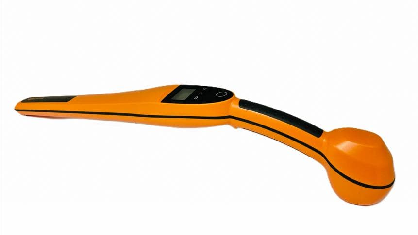
M5VG03307
Apr 24, 2026Handheld EID Tag Reader HR0
Equipment Class
DCD - Part 15 Low Power Transmitter Below 1705 kHz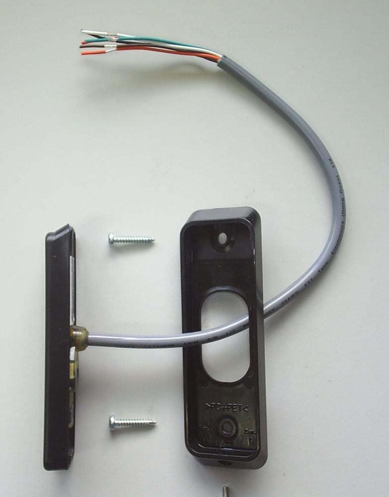
M5VC30040XB
Mar 28, 2023Prox Readers T10 Mifare
Equipment Class
DXX - Part 15 Low Power Communication Device Transmitter
M5VC30047XB
Feb 16, 2022Prox Readers T15 Mifare
Equipment Class
DXT - Part 15 Low Power Transceiver, Rx Verified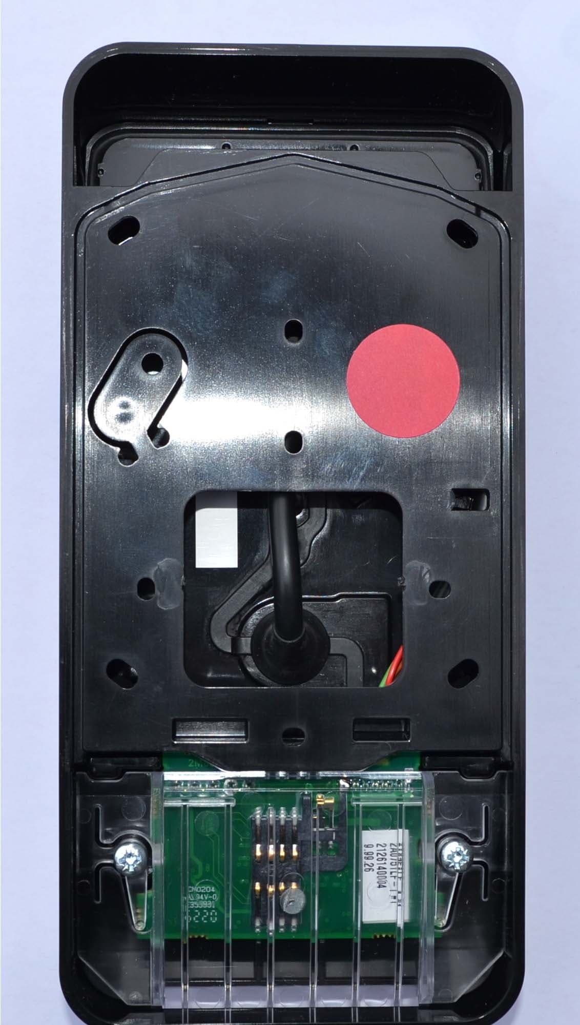
M5VC30550X
Jul 28, 2021Prox Readers T21 PIV
Equipment Class
DXT - Part 15 Low Power Transceiver, Rx Verified
M5VC30049X
Aug 19, 2020Prox Readers T30
Equipment Class
DXT - Part 15 Low Power Transceiver, Rx Verified