M5ZLSX1Wireless limit switch
Mesa Laboratories, Inc.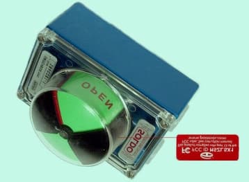
Click to zoom
Application Details
- Equipment Class
- DSC - Part 15 Security/Remote Control Transmitter
- Date of Grant
- Jul 12, 2001
- Application Purpose
- Original Equipment
- Date of Application
- Jul 12, 2001
- Equipment Note
- Wireless limit switch
- Frequency Range
- 417.90000000 - 418.20000000
- Company
- Mesa Laboratories, Inc.
- Country
- United States
Documents & Files
Document Text
Text extracted from the exhibit documents filed with the FCC. Open a document above to read the original.
Users Manual
FCC ID: M5ZLSX1 Installation and Operation Instructions for the Limit Switch Transmitter model LSX-1. Point Six, Inc. Wireless Engine Parameter Transmitter Model WOW-LSX1 Installation and Operation Instructions The WOW-LSX1 wireless limit switch transmitter transmits opened-closed status and counter data with a unique serial number to a 418 MHz receiver. The LSX1 is enclosed in a metal limit switch enclosure with a plastic dome lid. The LSX-1 is a Lithium battery powered device that is mounted as a conventional limit switch on an automatic or manual valve actuator. The status and opened/closed counter values are transmitted once each minute. Application: Attach the LSX-1 as a conventional limit switch package to the valve actuator to be monitored. The LSX-1 is battery operated so no power connection is required. Remove the lid by backing out the four corner screws. Press the pushbutton located next to the limit switch package momentarily to start the adjustment LED function. For a period of four minutes two LEDs on the PCB will indicate the status of the opened/closed limit switches, this is provided as an adjustment aid for alignment of the magnetic limit switch actuators. During this four-minute adjustment period the LEDs will reflect the status of the limit switches. After this time period the LEDs will be turned off and will not follow the status of the limit switches. Battery: A 3.6 Volt lithium battery powers the WOWLSX1 wireless limit switch transmitter. The battery will last for more than 10 years in the. The user can replace the battery. THIS DEVICE COMPLIES WITH PART 15 OF THE FCC RULES, OPERATION IS SUBJECT TO THE FOLLOWING TWO CONDITIONS: (1) THIS DEVICE MAY NOT CAUSE HARMFUL INTERFERENCE AND (2) THIS DEVICE MUST ACCEPT ANY INTERFERENCE RECEIVED, INCLUDING INTERFERENCE THAT MAY CAUSE UNDESERED OPERATION FCC ID: M5ZLSX1 MADE IN USA Wireless Temperature Sensor Data Format The Point Six, Inc. 418 MHz wireless transmitters require a compatible receiver with the ability to receive, error check and provide RS232 and RS422/485 interface. This document describes the data format provided by the HA8-WOW, HA9-WOW or HA10- WO W 418 MHz. Receivers. The transmit packet from a receiver is approximately 15 milliseconds in duration and consists of 13 bytes of data: 1-byte ID/Mode field 8-byte serial number 2-byte temperature data 2-byte CRC-16 error check The WOW receivers processe this packet. The receivers perform a CRC-16 error check on the packet. If the data is not accurate it is discarded. When a packet is received that is error free it is converted to a 29-character packet and transmitted out the serial port at 19,200 Baud. The data is transmitted serially in ASCII Hex format and terminated with a CR character. This format requires two bytes for each byte of data; 14 data bytes x 2=28 plus the CR is 29 characters The resulting binary data format of the packet is: 1-byte ID fieldthis field will contain a byte whose LSBit indicates the service state of the transmitter, 0=normal, 1=service mode. 8-byte serial#this field contains the serial number of the 1-Wire sensor. 2-byte temperaturethis field contains the temperature data stored MSB first in two's compliment 16-bit form of 1/16 deg. C units. 2-byte CRC-16this is the originally received data packet CRC as described above. 1-byte checksumthe checksum is a mod 256 sum of all the ASCII character values in the response but does not include the CR Example: “ LSX” Wireless Limit Switch Transmitter 91 F1D61300050000070000BD2DE1 <CR> string from an HA8 11F1D61300050000070000BD2DE1<CR> string from an HA9 The device type field: LSX has device type 91/11 hex. A 90/10 hex when in service mode. 91F1D61300050000070000BD2DE1<CR> string from an HA8 11F1D61300050000070000BD2DE1<CR> string from an HA9 The MS-30 bits of these 4-bytes are the serial number of the LSX. The LS-2 bits are the status flags for the open and closed limit switches. The LS bit (bit-0) is the Open switch flag and the next most significant bit (bit-1) is the Closed switch flag. 91F1D61300050000070000BD2DE1<CR> string from an HA8 11F1D61300050000070000BD2DE1<CR> string from an HA9 This 24-bit field is the Open counter stored LS-byte first the value shown is a count of 5 open cycles. 11F1D61300050000070000BD2DE1<CR> string from an HA8 11F1D61300050000070000BD2DE1<CR> string from an HA9 THIS 24-BIT FIELD IS THE CLOSED COUNTER STORED LS-BYTE FIRST, THE VALUE SHOWN IS A ACCOUNT OF 7 CLOSED CYCLES. 91F1D61300050000070000BD2DE1<CR> string from an HA8 11F1D61300050000070000BD2DE1<CR> string from an HA9 This field is the CRC-16 error check as was originally received and checked. This CRC is over the first 11 bytes of the packet starting with the device type and ending with inclusion of the temperature data. 91F1D61300050000070000BD2DE1<CR> string from an HA8 11F1D61300050000070000BD2DE1<CR> string from an HA9 This field is the mod 256 sum of all the ASCII character values in the response but does not include the <CR>. 91F1D61300050000070000BD2DE1<CR> string from an HA8 11F1D61300050000070000BD2DE1<CR> string from an HA9 This is the CR terminator, 0Dhex. FCC Radio Frequency Interference Statement Wireless Limit Switch Transmitter FCC ID: M5ZLSX1 NOTE: This equipment has been tested and found to comply with the limits for a Class B digital device, pursuant to Part 15, Subpart B, of the FCC Rules. This equipment generates, uses, and can radiate radio frequency energy. If not installed and used in accordance with the instructions, it may cause interference to radio communications. The limits are designed to provide reasonable protection against such interference in a residential situation. However, there is no guarantee that interference will not occur in a particular installation. If this equipment does cause interference to radio or television reception, which can be determined by turning the equipment off and on, the user is encouraged to try and correct the interference by one or more of th…
Text truncated - open the document above for the full version.
Attestation Statements
%PDF-1.2 %âãÏÓ 8 0 obj << /Length 9 0 R /Filter /FlateDecode >> stream H‰-VÛnã6•ýˆÿü•È•‰BJÔí-Ýl ̃ô¡h‹•]•Ø•F¢mv%Ñ¥ ̈ ̧Þ ̄ïð¢‹í ̄©·E•X– ɹ sfÞ ̄W% œ”Q• ̃¬?¬ ̊Ø?½...Õý# ́J#ÂðýfE"Bò•+ÀG– P|<ÀÍ ̈Á5ü¤#xPíÞ ̈îö•¬ÿ\•," ̆šAƒpÿH ÆÞ†»-Gqá/ƒ;|çOßÑ8ÊãpåÌsJÊå $BƒÞz••Éé wîWk •îˆ½Ÿ fÎõ Í‚åþøzÇ»ÏpT ̃l”¶Ÿ• †^v¢ï#g‰²Ä†ê•‘1õ×c±u¡t<GÊ1ËõNöpà=p8ˆ¦ ́¥·¼“_Dı¼«¡ÂÂ5 ̊àû}#+ n¤ê¼ÿ8u]ù×þ1;Z”c`1 Ç~ uaØdÆ–u¶ ́•É•pœù•;þ,@uÍ•ÿ }? ̊0 ̃í6R· ;Ì •Ú¾ÛjÞ•06Á‹ð•ß‚eø/uËŸ: êëú=ßϳ •?H}@e”dWu3‹Ë 6 ¾›ˆjn8•þÔ ̊[ıƒoŒèıh±WÚ@-D• 2ø[m+‚-ÅŸx-»-ƒš=ï½%IT°Ù_ ÓÉ_œ ̆‡Ø Í·ˆ yƒ}P›1k–EÉ ̆ÎËÙ`)‚ ́ën3t5oEgx ̃¢Å–N]¢ ±v®)KšÍe! ́3ð=ì ̆ÿ•¢D8Œ¹#Èı• ̆•©~•~¿o¿KÚ•î¤ ̧Öq2³‹ ²Ë»ı•ÉYTœ#ŠÑl&fâ ̄ª ¤éA•:ØpÙô®1c¹•ÙJ•J”9-º*R6ÑŠfi8÷ ̈Uëu¦–}5 ̧&؆Z·μx– •Â¦-Ì•ªc...È•yK3•aôgù¤³Ð¤¡•O¢‘ˆ©kíUJkQY2bn•AÔ È;( P-x/– ΰ†1iÔöÓ Ï&N•ÒƒîÜtðîhÐOšý ’oî)!íoŸÞ¡&Œõ÷wO‘™±Y i•, ́JÛhy‡¾ë÷¾ØE•¥×±4ıμvpLØ••¾™ w¾ ̊‡ è¼R!0Q¿lA•n[ÁûA K•¬ÐÐÔ!™" ²s,%Ù„%ʈ– ́è‡Æ2-5} “‰½’ÖæNV;ô"Œ‡ÙãÃÕb1ú¡×²0 ÓNG•þÒ ̊ÛÙQ«± ̧Æ 8ŸMl‰x1ˆ^ ̇ßj P‘fçfT?ì ²μGüÊ› c/Ç•™çQö–ÄûCgJõ• O£< p? ̃w•bׇ°)0’-•7“1Ð(½ ̈o Ÿ,"±• ©¾d†|VŒåýu ]Ã;- sn¡±•ïbéùöÂäb±zk#ÊHT Tì ÙˆÞ¬Ÿ#'›Ò.Ã`ùÃJÖØw«•A\n ́w•i`‡Oˆ‰åðâ(¥QÎÔÐÃÇŸ?â•U••â~ã ̊hy þ•äÞqÍ ̆H\pi<n1(7e ̊‚Æy• > ̃ Òò‹Û0fŸn=©ÇY– F•Úñz“Ý ̃u%õé•‹•ßÏ’ÌíʶGF›iÚ÷8K¡å]' ́ã‡e ̃Ûš ü ́ó8ÝÜZs’•)&ª•ÙH쪕œm•Ñˆ¥•íYÁ¹p®^!I\— Ù ̃: ́È«Tt—ÿ;•§û7s ̈'M ïÖß O?¬Wÿ`:8•5 endstream endobj 9 0 obj 1138 endobj 4 0 obj << /Type /Page /Parent 5 0 R /Resources << /Font << /F0 6 0 R /F1 7 0 R >> /ProcSet 2 0 R >> /Contents 8 0 R >> endobj 6 0 obj << /Type /Font /Subtype /TrueType /Name /F0 /BaseFont /Arial /Encoding /WinAnsiEncoding >> endobj 7 0 obj << /Type /Font /Subtype /TrueType /Name /F1 /BaseFont /TimesNewRoman /Encoding /WinAnsiEncoding >> endobj 2 0 obj [ /PDF /Text ] endobj 5 0 obj << /Kids [4 0 R ] /Count 1 /Type /Pages /MediaBox [ 0 0 612 792 ] >> endobj 1 0 obj << /Creator (Microsoft Word ) /CreationDate (Friday, July 13, 2001 8:37:34 AM) /Title (Document1) /Author (Unknown) /Producer (Acrobat PDFWriter 3.02 for Windows) /Keywords () /Subject () >> endobj 3 0 obj << /Pages 5 0 R /Type /Catalog /DefaultGray 10 0 R /DefaultRGB 11 0 R >> endobj 10 0 obj [/CalGray << /WhitePoint [0.8678 1.0044 1.3013 ] /Gamma 0.6642 >> ] endobj 11 0 obj [/CalRGB << /WhitePoint [0.8678 1.0044 1.3013 ] /Gamma [0.6642 0.6642 0.6642 ] /Matrix [0.3067 0.153 0.0101 0.4062 0.7422 0.0817 0.2513 0.1048 0.7331 ] >> ] endobj xref 0 12 0000000000 65535 f 0000001773 00000 n 0000001647 00000 n 0000001990 00000 n 0000001266 00000 n 0000001681 00000 n 0000001409 00000 n 0000001524 00000 n 0000000021 00000 n 0000001243 00000 n 0000002087 00000 n 0000002180 00000 n trailer << /Size 12 /Root 3 0 R /Info 1 0 R /ID [<37789c71328487a07bfee6fc0d5a3df3><37789c71328487a07bfee6fc0d5a3df3>] >> startxref 2362 %%EOF
Cover Letter(s)
dBi Corporation Point Six, Inc. 391 Codell Drive Lexington, KY. 40509, USA July 2, 2001 Federal Communications Commission Equipment Approval Services re: FCC ID: M5ZLSX1 Gentlemen: Enclosed please find the Point Six, Inc. application for FCC Certification of the Point Six Limit Switch Transmitter, Model LSX-1. The test data submitted as part of this application were prepared by the dBi Corporation located at 131 French Ave, Winchester, KY. dBi Corporation has A2LA accreditation for EMC testing. Certificate number 1012.01 is valid to October 31, 2001. The facility used for radiated measurements is owned by Lexmark International, Inc. and was recognized by the Commission as meeting the requirements of section 2.948 of the Rules via a letter dated August 20, 1998. We submit the information in this application pursuant to the requirements of section 2.1033 and Part 15 of the Federal Communications Commission Rules and Regulations. We request that the Commission grant equipment authorization as soon as it is determined that the attached Application for Equipment Authorization is acceptable. We further request that the schematics and block diagrams of the Point Six Limit Switch Transmitter be treated as confidential information as provided for in 47 CFR Section 0.459 (d) (2). Point Six considers this information to be a trade secret. The schematics and block diagrams are in Word files (included with this application) and are listed as 01dBi018(Schematics) and 01dBi018(Block-Diag) respectively. Thank you in advance for your assistance. If further information is required concerning this application, please do not hesitate to contact me. Sincerely John I. Compton President, Point Six, Inc. dBi Corporation FCC ID: M5ZLSX1 List of Exhibits 1. Cover Letter, Word file 01dBi018(Cover-Ltr) 2. FCC 731 Form, Word file 01dBi018(731) 3. Test Report, Word file 01dBi018(Test-Report) 4. Timing Information, Word file 01dBi018(Timing) 5. FCC Label Information, Word file 01dBi018(FCC-Label) 6. Operational Description, Word file 01dBi018(Op-Discrp) 7. Functional Block Diagram (Confidential), Word file 01dBi018(Block-Diag) 8. Schematics (Confidential), Word file 01dBi018(Schematics) 9. Transmitted Bandwidth Measurements, Word file 01dBi018(BW-Meas) 10. Users Manual, Word file 01dBi018(User's Man) 11. External Pictures, Word file 01dBi018(External-Pics) 12. Internal Pictures, Word file 01dBi018(Internal-pics) 13. Setup Pictures, Word file 01dBi018(Setup-pics)
External Photos
FCC ID: M5ZLSX1 Overall view of the Point Six Limit Switch Transmitter Model LSX-1
ID Label/Location Info
FCC ID: M5ZLSX1 FCC label and location of the label on the product. FCC ID Label shown on the Limit Switch Transmitter, Model LSX-1
Internal Photos
FCC ID: M5ZLSX1 Top and Bottom View of the Point Six Limit Switch Transmitter Circuit Board, Model LSX-1
Operational Description
FCC ID: M5ZLSX1 Operational description of the Limit Switch Transmitter, Model LSX1 Description of the circuit functions, ground system and antenna of the Point Six, WOWLSX1 Wireless transmitter The WOWLSX1 limit switch transmitter is a lithium battery powered, microprocessor based, 418 MHz. transmitter that transmits switch status, open-state counter and closed-state counters and a unique 30-bit serial number. The microprocessor is brought up from a power down state every 1 second by a DS2417 time of day clock interrupt output. The microprocessor counts the total number of times that the limit switch inputs are activated and registers the current state of each opened or closed switch. The microprocessor counts the 1-second interrupt cycles from the DS2417 clock until the transmit period has expired. The microprocessor then combines the counts and switch status with serial number data from an onboard DS18B20 and transmits the entire data packet serially with a Linx Technologies TXM- 418-LC-R 418 MHz. Transmitter module. The microprocessor then powers down into a quiescent state to wait for the next interrupt from the DS2417 clock. The PC board bottom layer is a ground plane and the antenna is a 1/4-wave loop that has been hot upset into the PVC cover to form a spiral. The electronics is housed in a metal box with a plastic lid.
Test Report
Test Report FCC ID: M5ZLSX1 EUT: Point Six Limit Switch Transmitter, Model LSX-1 Manufactured by: Point Six, Inc. 391 Codell Drive Lexington, KY. 40509 Measurements According to: ANSI C63.4 (1992) Measurement Date: May 30, 2001 Testing Performed at: Lexmark International, Inc. Registered Open Field Test Site Development Lab. 740 New Circle Road, NW. Lexington, KY. 40511-1876 Accreditation Status of Test Facility: The Lexmark site was recognized by the Commission as meeting the requirements of section 2.948 of the FCC Rules via a letter dated August 20, 1998 and is presently on file with the Commission. Test Report FCC ID: M5ZLSX1 Testing Results: Harmonic Freq. (MHz) Meter Peak dB Meter Average dB Ant & Cable Factors dB/uV/m Total Peak dB/uV/m Limit Peak dB/uV/m Total Average dB/uV/m Limit Average dB/uV/m 1 418(V) 69.00* - 19.28 88.28 92.78 - 72.30 2 836(V) 10.00 QP - 25.16 35.16 QP 46.00 QP - - 3 1254(V) 10.69 - 24.60 35.29 74.00 - 54.00 4 1672(V) 20.56 -1.55 26.50 47.06 74.00 24.95 54.00 5 2090(V) 23.97 -1.26 28.10 52.07 74.00 23.84 54.00 6 2508(V) 11.85 -2.18 29.80 41.65 74.00 27.62 54.00 7 2926(V) 12.03 -1.60 31.50 43.53 74.00 29.90 54.00 8 3344(V) 12.06 -1.69 31.90 43.96 74.00 30.21 54.00 9 3762(H) 14.30 -2.13 32.40 46.70 74.00 30.27 54.00 10 4180(V) 11.10 -1.91 32.90 44.00 74.00 30.99 54.00 * Indicates max. radiation orientation; the product was measured at three different orientations. Sample Calculation: From FCC Rules, Paragraph 15.231(e) Frequency: 260-470 MHz. Amplitude: 1500-5000 uV/m For 418 MHz. L(limit)=((418-260)/(470-260))(5000-1500)+1500 L = 4133 uV/m L(dB/uV/m) = 20 Log (4133) L = 72.3 dB/uV/m (AVG) L(Peak) = Avg. + 20 dB L(Peak) = 72.3 + 20 = 92.3 dB/uV/m Signed:________________________________Date:_____________ D.R. Bush, PE, NCE, President dBi Corporation FCC ID: M5ZLSX1 The photo below indicates that the 20 dB transmitted bandwidth of the Point Six Limit Switch Transmitter is 46 kHz. This is well within the maximum bandwidth specified by 47CFR15.233(c). Signed:______________________ ________Date:_________ D. R. Bush, PE, NCE, President dBi Corporation To Whom It May Concern: Point Six , Inc. 391 Codell Drive Lexington, Ky. 40509 606-266-3606 Fax 271-0702 The Point Six, Inc. wireless limit switch transmitter (model LSX-1) transmits a 15-16 millisecond packet once each 600-10 seconds. This is identical to the data packet timing of a previously certified “M5ZWOW”. I will restate this timing below. The packet consists of transmitter-on/transmitter-off timing that represents the serial number and humidity/temperature data. The duty cycle is approximately 50%. The packet time can vary with serial number between 14-16 milliseconds. The packet data is controlled by a microprocessor whose timing is based on a ceramic resonator that is very stable. The packet below (figure #2) illustrates a typical data packet, the worst case, 16 milliseconds, cannot be shown because serial number would have to be forced to make this so. Figure #1 illustrates the overall timing; a packet is sent each 10 seconds in this worst case. The battery used during the tests was new and was a standard 3.6 Volt Lithium cell. The battery is a 3.6 Volt Lithium chemistry, which has a flat discharge curve from new to about 90% used. In this application the battery requires about 5 years to discharge to the point that it cannot be used. The battery was used for no other purpose and had operated in the test unit for only a short time when the test was performed. The label will be Flexcon 2 mil PM200S mylar with a Flexcon 1 mil PM100C Polyester laminate. John I. Compton President, Point Six, inc. Figure #1 Overall timing Figure #2 Packet Timing
Test Setup Photos
FCC ID: M5ZLSX1 Radiated Test Setup Picture of the Point Six Limit Switch Transmitter, Model LSX-1
Contact Information
Applicant
Jasmine Stone(Director of Quality)
Test Firm
Lexmark International, Inc.John Fessler
Technical Specifications
| # | Rule Parts | Frequency Range | Power Output |
|---|---|---|---|
| 1 | 15.231(e) | 417.9 MHz - 418.2 MHz | - |
Other Applications from Mesa Laboratories, Inc.
M5ZTMPC
Apr 23, 2012IR Point Sensor
Equipment Class
DSC - Part 15 Security/Remote Control Transmitter
M5ZFDEZIO
Aug 15, 2007IR Field Disturbance Sensor
Equipment Class
DSC - Part 15 Security/Remote Control Transmitter
M5ZP6HWSO
Mar 14, 2007Temperature Sensor
Equipment Class
DSC - Part 15 Security/Remote Control Transmitter
M5ZIRPROX2
Apr 18, 2006IR Proximity Counter
Equipment Class
DSC - Part 15 Security/Remote Control Transmitter
M5ZTHL
Mar 10, 2003Wireless Temperature/Humidity Sensor
Equipment Class
DSC - Part 15 Security/Remote Control Transmitter