M5ZWOWTHLPart 15.231(e) wireless sensor
Mesa Laboratories, Inc.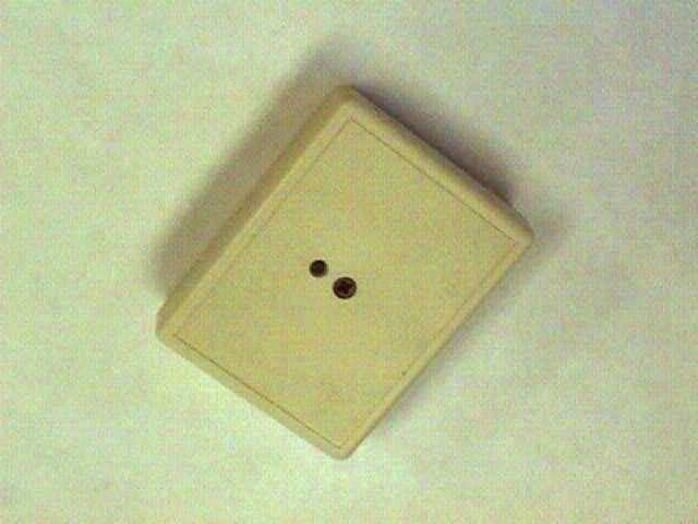
Click to zoom
Application Details
- Equipment Class
- DXX - Part 15 Low Power Communication Device Transmitter
- Date of Grant
- Nov 27, 2000
- Application Purpose
- Original Equipment
- Date of Application
- Nov 27, 2000
- Equipment Note
- Part 15.231(e) wireless sensor
- Frequency Range
- 417.90000000 - 418.20000000
- Company
- Mesa Laboratories, Inc.
- Country
- United States
Documents & Files
Document Text
Text extracted from the exhibit documents filed with the FCC. Open a document above to read the original.
Users Manual
FCC ID: M5ZWOWTHL Installation and Operation Instructions for the Wireless Temp/RH or Light Sensor. Point Six, Inc. Wireless Temperature/Relative-Humidity or Light Sensor Model WOWTHL Installation and Operation Instructions The WOWTHL wireless temperature Relative-Humidity or Light level sensor transmits a digital temperature, relative-humidity (or light level) and a unique serial number to a 418 MHz receiver. The WOWTHL is enclosed in a high impact ABS enclosure for direct surface mounting in the environment to be measured. The WOWTHL is battery operated. Application: Apply the sensor to the surface to be monitored with double-sided adhesive tape. Make sure that the side labeled with FCC ID is visible and away from any metal surfaces. Service Function: The wireless sensor has an installation mode switch. A momentary push of this switch will start the convert/transmit cycles. When new and until this button is pushed the WOWTHL will not transmit. The WOWTHL will transmit a special installation status mark in the data packet immediately after the installation/start switch is pushed. After the start a push of the installation switch will result in the immediate transmission of temperature, relative-humidity (or light level) ID and installation status mark. Battery: A 3.0-3.6 Volt lithium battery powers the WOWTHL wireless sensor. The battery will last for more than 10 years in the idle state (as shipped from the manufacturer). The WOWTHL will transmit data for as long as 3 years at a rate of once each minute once started. The WOWTHL is completely covered with a water resistant rubber coating to protect the electronics from the environment and condensation. The user cannot replace the battery. The WOWTHL may be placed in a quiescent state (battery life greater than 10 years) by holding the installation switch closed for more than 12 seconds. FCC ID: M5ZWOWTHL Wireless Sensor Data Format The Point Six, Inc. 418 MHz wireless sensors require a compatible receiver with the ability to receive, error check and provide RS232 and RS422/485 interface. This document describes the data format provided by the HA8-wow 418 MHz. Receiver. The transmit packet from a receiver is approximately 15 milliseconds in duration and consists of 13 bytes of data: 1-byte ID/Mode field 8-byte serial number 2-byte temperature/relative-humidity or temperature/light level 2-byte CRC-16 error check The HA8-wow receiver processes this packet. The receiver performs a CRC-16 error check on the packet. If the data is not accurate it is discarded. When a packet is received that is error free it is converted to a 29-character packet and transmitted out the serial port at 19,200 Baud. The data is transmitted serially in ASCII Hex format and terminated with a CR character. This format requires two bytes for each byte of data; 14 data bytes x 2=28 plus the CR is 29 characters. See the HA8-wow specification for details. The resulting binary data format of the packet is: 1-byte ID field this field will contain a byte whose LSBit indicates the service state of the transmitter, 0=normal, 1=service mode. 8-byte serial# this field contains the serial number of the 1-Wire sensor. 2-byte data this field contains the temperature %RH or temperature/light level stored MSB first. The MSbit of the MSB is the sign bit for the temperature value which is stored as the LSB in ½ deg C units. THIS DEVICE COMPLIES WITH PART 15 OF THE FCC RULES, OPERATION IS SUBJECT TO THE FOLLOWING TWO CONDITIONS: (1) THIS DEVICE MAY NOT CAUSE HARMFUL INTERFERENCE AND (2) THIS DEVICE MUST ACCEPT ANY INTERFERENCE RECEIVED, INCLUDING INTERFERENCE THAT MAY CAUSE UNDESERED OPERATION FCC ID: M5ZWOWTHL MADE IN USA FCC ID: M5ZWOWTHL Bits 0-6 of the MSB contain the RH value in %RH (0-100%). In the case of light level bits 0-6 of the MSB is the relative light level. 2-byte CRC-16 this is the originally received data packet CRC as described above. 1-byte checksum the checksum is a mod 256 sum of all the ASCII character values in the response but does not include the CR Example: C8 28AE9105000000AA2D2DD474AB<CR> This field is the mode indicator, the LS-bit which indicates the service state of the transmitter, C8=normal, C7=service mode. C828AE9105000000AA 2D2DD474AB <CR> This field is the unique serial number of the 1-Wire sensor. C828AE9105000000AA2D2D D474AB <CR> This is the temperature and %RH or light level field. The MSBit of the MSByte is low so the temperature is a positive number, 2D is 45 so the temperature is +22.5 C. The %RH is 45. A value on this field of A1F2 would represent a temperature of (242-256)/2 or -7 C and a %RH or 33. Temperature is stored in the LSByte, if the MSBit of the MSB is 1 than the temperature is negative and the conversion math is (n-256)/2 otherwise use n/2. The light level is stored just as %RH is stored and is a relative number, higher light levels result in a higher number and lower light levels result in a lower number. C828AE9105000000AA2D2DD474 AB <CR> This field is the CRC-16 error check as was originally received and checked. This CRC is over the first 11 bytes of the packet starting with the mode flags and ending with inclusion of the temperature data. C828AE9105000000AA2D2DD474AB <CR> This field is the mod 256 sum of all the ASCII character values in the response but does not include the <CR>. C828AE9105000000AA2D2DD474AB <CR> This is the CR terminator, 0Dhex. FCC ID: M5ZWOWTHL FCC Radio Frequency Interference Statement Wireless Temperature Sensor FCC ID: M5ZWOWTHL NOTE: This equipment has been tested and found to comply with the limits for a Class B digital device, pursuant to Part 15, Subpart B, of the FCC Rules. This equipment generates, uses, and can radiate radio frequency energy. If not installed and used in accordance with the instructions, it may cause interference to radio communications. The limits are designed to provide reasonable protection against such interference in a residential situation. However, there is no guarante…
Text truncated - open the document above for the full version.
External Photos
FCC ID: M5ZWOWTHL Wireless Relative Humidity/Temp. - Light Level Sensor Exterior Overall View.
ID Label/Location Info
FCC ID: M5ZWOWTHL FCC label and location of label on the product. THIS DEVICE COMPLIES WITH PART 15 OF THE FCC RULES, OPERATION IS SUBJECT TO THE FOLLOWING TWO CONDITIONS: (1) THIS DEVICE MAY NOT CAUSE HARMFUL INTERFERENCE AND (2) THIS DEVICE MUST ACCEPT ANY INTERFERENCE RECEIVED, INCLUDING INTERFERENCE THAT MAY CAUSE UNDESERED OPERATION FCC ID: M5ZWOWTHL MADE IN USA FCC ID Label shown on the bottom of Wireless Temp/RH/Light Sensor, Model WOW-RHT/LGT FCC ID M5ZWOWTHL THIS PRODUCT COMPLIES WITH PART 15 OF THE FCC RULES. SEE INSTRUCTION MANUAL
Internal Photos
FCC ID: M5ZWOWTHL Top View of the Wireless RH/Temp. - Light Level Sensor Board. FCC ID: M5ZWOWTHL Bottom View of the Wireless RH/Temp. - Light Level Sensor Board.
Operational Description
FCC ID: M5ZWOWTHL Operational description of the Wireless Sensor, Model WOWTHL Description of the circuit functions, ground system and antenna of the Point Six WOWTHL Wireless transmitter: The WOWTHL wireless temperature-relative humidity or light level sensor is a lithium battery operated, microprocessor based, 418 MHz. transmitter that transmits both digital temperature data, a unique 64-bit serial number and either % Relative humidity or light level data. The microprocessor is brought up from a power down state every 4 seconds by a DS2417 time of day clock interrupt output. Relative humidity and light data are taken from a 12-bit ADC. The temperature is measured with a DS18B20 digital temperature sensor, which has a unique 64-bit serial number that can be read by the microprocessor. The microprocessor counts the 4-second interrupt cycles from the DS2417 clock until the transmit period has expired. The microprocessor then reads the temperature from the previous temperature conversion, combines it with the serial number and % RH or light level data and transmits the entire data packet serially with a Linx Technologies TXM- 418-LC-R 418 MHz. Transmitter module. The microprocessor then starts another temperature conversion cycle and powers down into a quiescent state to wait for the next interrupt from the DS2417 clock. The PC board bottom layer is a ground plane and the antenna is a 1/4-wave loop that has been hot upset into the ABS cover to form a spiral. The entire electronics is coated with a rubber conformal coating to protect it from condensation. The ground plane (bottom layer) is not coated.
Test Report
Test Report FCC ID: M5ZWOWTHL EUT: Wireless Temperature/RH/Light Sensor, Models WOW-RHT and WOW-LGT Manufactured by: Point Six, Inc. 391 Codell Drive Lexington, KY. 40509 Measurements According to: ANSI C63.4 (1992) Measurement Date: October 16, 2000 Testing Performed at: Lexmark International, Inc. Registered Open Field Test Site Development Lab. 740 New Circle Road, NW. Lexington, KY. 40511-1876 Accreditation Status of Test Facility: The Lexmark site was recognized by the Commission as meeting the requirements of section 2.948 of the FCC Rules via a letter dated August 20, 1998 and is presently on file with the Commission. Test Report FCC ID: M5ZWOWTHL(Model WOW-LGT) Testing Results: Harmonic Freq. (MHz) Meter Peak dB Meter Average dB Ant & Cable Factors dB/uV/m Total Peak dB/uV/m Limit Peak dB/uV/m Total Average dB/uV/m Limit Average dB/uV/m 1 418 67.10 33.00 19.28 86.38 92.30 52.28 72.30 2 836 2.0 QP - 25.16 27.16 QP 46.00 QP - - 3 1254 10.74 -3.96 24.60 35.34 74.00 20.64 54.00 4 1672 11.38 -2.63 26.50 37.88 74.00 23.87 54.00 5 2090 11.42 -2.25 28.10 39.52 74.00 25.85 54.00 6 2508 10.87 -1.95 29.80 40.67 74.00 27.85 54.00 7 2926 11.14 -1.55 31.50 42.64 74.00 29.95 54.00 8 3344 11.12 -1.40 31.90 43.02 74.00 30.50 54.00 9 3762 11.32 -1.55 32.40 43.72 74.00 30.85 54.00 10 4180 11.23 -1.76 32.90 44.13 74.00 31.14 54.00 Sample Calculation: From FCC Rules, Paragraph 15.231(e) Frequency: 260-470 MHz. Amplitude: 1500-5000 uV/m For 418 MHz. L(limit)=((418-260)/(470-260))(5000-1500)+1500 L = 4133 uV/m L(dB/uV/m) = 20 Log (4133) L = 72.3 dB/uV/m (AVG) L(Peak) = Avg. + 20 dB L(Peak) = 72.3 + 20 = 92.3 dB/uV/m Signed:________________________________Date:_____________ D.R. Bush, PE, NCE, President dBi Corporation Test Report FCC ID: M5ZWOWTHL(Model WOW-RHT) Testing Results: Harmonic Freq. (MHz) Meter Peak dB Meter Average dB Ant & Cable Factors dB/uV/m Total Peak dB/uV/m Limit Peak dB/uV/m Total Average dB/uV/m Limit Average dB/uV/m 1 418 65.00 32.00 19.28 84.28 92.30 51.28 72.30 2 836 12.60 QP - 25.16 37.76 QP 46.00 QP - - 3 1254 10.60 -2.87 24.60 35.20 74.00 21.73 54.00 4 1672 12.08 -2.61 26.50 38.58 74.00 23.89 54.00 5 2090 12.80 -2.23 28.10 40.90 74.00 25.87 54.00 6 2508 13.04 -1.94 29.80 42.84 74.00 27.86 54.00 7 2926 13.15 -0.93 31.50 44.65 74.00 30.57 54.00 8 3344 12.48 -1.54 31.90 44.38 74.00 30.36 54.00 9 3762 12.70 1.50 32.40 45.10 74.00 33.90 54.00 10 4180 12.57 1.28 32.90 45.47 74.00 34.18 54.00 Sample Calculation: From FCC Rules, Paragraph 15.231(e) Frequency: 260-470 MHz. Amplitude: 1500-5000 uV/m For 418 MHz. L(limit)=((418-260)/(470-260))(5000-1500)+1500 L = 4133 uV/m L(dB/uV/m) = 20 Log (4133) L = 72.3 dB/uV/m (AVG) L(Peak) = Avg. + 20 dB L(Peak) = 72.3 + 20 = 92.3 dB/uV/m Signed:________________________________Date:_____________ D.R. Bush, PE, NCE, President dBi Corporation
Test Report
Dear Mr. Quinlan: The Point Six, Inc. wireless humidity/temperature transmitter transmits a 15-16 millisecond packet once each 600-10 seconds. This is identical to the data packet timing of a previously certified “M5ZWOW”. I will restate this timing below. The packet consists of transmitter-on/transmitter-off timing that represents the serial number and humidity/temperature data. The duty cycle is approximately 50%. The packet time can vary with serial number between 14-16 milliseconds. The packet data is controlled by a microprocessor whose timing is based on a ceramic resonator that is very stable. The packet below (figure #2) illustrates a typical data packet, the worst case, 16 milliseconds, cannot be shown because serial number would have to be forced to make this so. Figure #1 illustrates the overall timing; a packet is sent each 10 seconds in this worst case. The battery used during the tests was new and was a standard 3.6 Volt Lithium cell. The battery is a 3.6 Volt Lithium chemistry, which has a flat discharge curve from new to about 90% used. In this application the battery requires about 5 years to discharge to the point that it cannot be used. The battery was used for no other purpose and had operated in the test unit for only a short time when the test was performed. The label will be Flexcon 2 mil PM200S mylar with a Flexcon 1 mil PM100C Polyester laminate. I gave your question #3 to Don Bush of dBi Corp. Donald R. Bush tel 606-744-8695 dBi Corporation fax 606-737-0747 131 French Avenue [email protected] Winchester, KY 40391 USA This is his response: “In accordance with ANSI C63.4(1992), para 8.1, we performed a continuous azimuth search in both antenna polarities. In each polarity, after determining the maximum azimuth, the antenna height was varied from one to four meters to determine the maximum radiation. This measurement was performed at both 418 and 836 MHz. on the open area test sight (OATS). Because the radiation at higher harmonics was below the receiver noise when measured within the Lexmark 3-meter semi-anechoic chamber, these measurements were not repeated on the OATS.” John I. Compton President, Point Six, inc. Point Six , Inc. 383 Codell Drive Lexington, Ky. 40509 606-266-3606 Fax 271-0702 Figure #1 Overall timing Figure #2 Packet Timing
Test Report
TCB questions Dear Mr Compton, Thank you for you application package for certification of your wireless sensor product. The following issues need to be resolved: 1. Please provide a statement that the label will be permanently affixed to the product and supply label material details. 2. Please confirm new batteries were used for the testing. 3. Please provide a statement that the testing was conducted in 3 orthogonal planes. 4. The averaging factor must be derived from an analysis of the worst case duty cycle. We cannot accept the average measurements based on using an average detector. Oscilloscope photos or zero span spectrum analyzer photos/plots must be presented to document the worst case 100mS duty cycle. This analysis will result in an averaging factor which shall be deducted from the peak measurements to derive the average measurements. Note that if the averaging factor exceeds 20dB, then 20dB shall be used. 5. We need documentation of the unit's compliance with the transmission time limitations of 15.231(e). Oscilloscope plots of the unit's transmission duration and periodicity would be sufficient. Best regards Barry C. Quinlan Certification Manager Curtis-Straus LLC
Test Report
FCC ID: M5ZWOWTHL The top photo indicates that the 20 dB transmitted bandwidth of the Temperature/Relative Humidity sensor (Model WOW-RHT) is 46 kHz. and the bottom photo indicates that the 20 dB transmitted bandwidth of the Temperature/Light sensor (Model WOW-LGT) is 48 kHz. These are well within the maximum bandwidth specified by 47CFR15.233(c).
Test Report
dBi Corporation 131 French Avenue Winchester Kentucky 40391 tel 606-744-8695 fax 606-737-0747 Rotational measurements of Wireless One-wire Temperature/Humidity Light sensor- transmitter on 11/24/00. Note that the maximum difference with respect to axis and antenna polarization is 5 dB peak and 4 dB average. The original prescan data taken on this unit resulted in a maximum peak reading of 64.87dB peak and 36 dB average. The OATS raw data were 67.1 dB peak and 33 dB average. Ant Horiz Meter(dB) Cable loss Ant. fact Total Limit Flat (Pk) 59 2.5 16.76 78.26 92.3 Side (Pk) 61 2.5 16.76 80.26 92.3 End (Pk) 63 2.5 16.76 82.26 92.3 Flat (Av) 28 2.5 16.76 47.26 72.3 Side (Av) 29 2.5 16.76 48.26 72.3 End (Av) 31 2.5 16.76 50.26 72.3 Ant Vert Meter(dB) Cable loss Ant. fact Total Limit Flat (Pk) 60.5 2.5 16.76 79.76 92.3 Side (Pk) 64 2.5 16.76 83.26 92.3 End (Pk) 64 2.5 16.76 83.26 92.3 Flat (Av) 29 2.5 16.76 48.26 72.3 Side (Av) 30 2.5 16.76 49.26 72.3 End (Av) 32 2.5 16.76 51.26 72.3 Donald R. Bush
Test Report
FCC ID: M5ZWOWTHL Modified Test Results Table for Model WOW-RHT Harmonic Freq. (MHz) Meter Peak dB Ant & Cable Factors dB/uV/m Total Peak dB/uV/m Limit Peak dB/uV/m Total Average dB/uV/m Limit Average dB/uV/m 1 418 65.00 19.28 84.28 92.30 62.38 72.30 2 836 12.60 QP 25.16 37.76 QP 46.00 QP - - 3 1254 10.60 24.60 35.20 74.00 13.30 54.00 4 1672 12.08 26.50 38.58 74.00 16.68 54.00 5 2090 12.80 28.10 40.90 74.00 19.00 54.00 6 2508 13.04 29.80 42.84 74.00 20.94 54.00 7 2926 13.15 31.50 44.65 74.00 22.75 54.00 8 3344 12.48 31.90 44.38 74.00 22.48 54.00 9 3762 12.70 32.40 45.10 74.00 23.20 54.00 10 4180 12.57 32.90 45.47 74.00 23.57 54.00 Modified Test Results Table for Model WOW-LGT Harmonic Freq. (MHz) Meter Peak dB Ant & Cable Factors dB/uV/m Total Peak dB/uV/m Limit Peak dB/uV/m Total Average dB/uV/m Limit Average dB/uV/m 1 418 67.10 19.28 86.38 92.30 64.48 72.30 2 836 2.0 QP 25.16 27.16 QP 46.00 QP - - 3 1254 10.74 24.60 35.34 74.00 13.44 54.00 4 1672 11.38 26.50 37.88 74.00 15.98 54.00 5 2090 11.42 28.10 39.52 74.00 17.62 54.00 6 2508 10.87 29.80 40.67 74.00 18.77 54.00 7 2926 11.14 31.50 42.64 74.00 20.74 54.00 8 3344 11.12 31.90 43.02 74.00 21.12 54.00 9 3762 11.32 32.40 43.72 74.00 21.82 54.00 10 4180 11.23 32.90 44.13 74.00 22.23 54.00
Test Setup Photos
FCC ID: M5ZWOWTHL Test Set-up Picture of the Point Six Wireless RH/Temp. - Light Level Sensor
Contact Information
Applicant
Jasmine Stone(Director of Quality)
Technical Contact
Point Six, Inc.John I Compton
[email protected]859 266 3606
391 Codell Drive · Lexington, Kentucky · United States
Non-Technical Contact
Point Six, Inc.John I Compton
[email protected]859 266 3606
Test Firm
Lexmark International, Inc.John Fessler
Technical Specifications
| # | Rule Parts | Frequency Range | Power Output |
|---|---|---|---|
| 1 | 15C | 417.9 MHz - 418.2 MHz | - |
Other Applications from Mesa Laboratories, Inc.
M5ZTMPC
Apr 23, 2012IR Point Sensor
Equipment Class
DSC - Part 15 Security/Remote Control Transmitter
M5ZFDEZIO
Aug 15, 2007IR Field Disturbance Sensor
Equipment Class
DSC - Part 15 Security/Remote Control Transmitter
M5ZP6HWSO
Mar 14, 2007Temperature Sensor
Equipment Class
DSC - Part 15 Security/Remote Control Transmitter
M5ZIRPROX2
Apr 18, 2006IR Proximity Counter
Equipment Class
DSC - Part 15 Security/Remote Control Transmitter
M5ZTHL
Mar 10, 2003Wireless Temperature/Humidity Sensor
Equipment Class
DSC - Part 15 Security/Remote Control Transmitter