M65NVX1201H2-Way Security Transceiver
Super Nova Co Ltd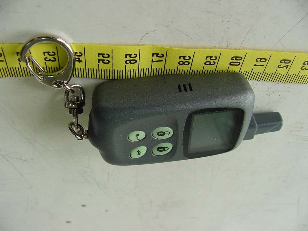
Click to zoom
Application Details
- Equipment Class
- DSR - Part 15 Remote Control/Security Device Transceiver
- Date of Grant
- Aug 08, 2002
- Application Purpose
- Original Equipment
- Date of Application
- Aug 08, 2002
- Equipment Note
- 2-Way Security Transceiver
- Frequency Range
- 433.92000000 - 433.92000000
- Company
- Super Nova Co Ltd
- Country
- Taiwan
Documents & Files
Document Text
Text extracted from the exhibit documents filed with the FCC. Open a document above to read the original.
Users Manual
RW6400T 2 Way Transmitter (TR5) Operation manual LCD Panel Function Shown: To Anti-Car Jacking: Main Unit Parking Flash 2 times and LED flash Quickly (no picture shown). Button 5: a. Show the company Logo or the last message. b. Keep press 3” to Change Channel I or II ( 1 st Car or 2 nd Car). c. Press 5 times to Voice or null voice prompt for button operation. Button 5 ST A RT Basic function of button : Button 1 : a. Arm. b. Keep press 3 second to Panic. Button 2 : Disarm (and it will open the central look on driver side.) than press one more time in 5”, it will open the central lock on other doors. Button 3 : a. Remote 1 st aux. output (Trunk pop). b. Keep press 2-3” to remote 2 nd aux. output. Button 4 : Remote start --- press again to off. Button 1+2 : a. When arming --- keep press 3” to all (shock & option) sensor bypass. b. When disarm --- press 3” to valet mode, when keep 6” to valet park mode. Button 1+3 : To anti-car jacking. Button 2+4 : Chirp defeat arm / disarm TR5 Layout Description LCD Panel Button 2 Button 4 (AUX) Button 1 Button 3 Arm (1 st Car) Disarm (2 nd Car) Chirp defeat disarm Chirp defeat arm Panic Door open 1 st aux. output Trunk POP (or Hood Open) Data translate..! Low battery Remote Start (Picture move) Valet Park (flash 20 ti) Valet Warn away IGN VLT VLT Transmitter learning Shock Sensor (hammer move) L Central Unlock Central Lock Logo CSP USA P 6400 Updated Program Option Chart PROGRAM: RW6400C0.HEX Option Option Description Fac. Pre-set Tx Button Tx Button Tx Button Tx Button 1 Tach Learning Learning 2 Auto Lock With Ignition ON OFF ON 3 Aggressive Arm Mode OFF ON OFF 4 Active Re-Arm Mode OFF ON OFF 5 Passive Lock OFF ON OFF 6 Parking Light Illumination on Disarm ON OFF ON 7 Valet Park Protection Mode or Trunk Mode Trunk Valet Park Trunk 8 Passive Car-Jacking Mode Remote Car-Jacking Passive Car-Jacking Remote Car-Jacking 9 Siren Confirmation for Remote Start ON OFF ON 10 Aux Disarm ON OFF ON 11 5/60 Second Warning Chirps (Normal Car/Dome Light Delay Car) 60 sec. 5 sec. 60 sec. 12 Door Lock Pulse Time 0.75 sec. 3.0 sec. 0.75 sec. 13 Double Unlock Pulse 1 Pules 2 Pules 1 Pules 14 Remote Start Run Time 24 min. 12 min. 24 min. 36 min. 48 min 15 Option Reset Reset ST A RT (RS Serial ) Voltage Detect setting use two jumpers (1=short, 0=open) P 1(0), P2(0) = 91% P1(1), P2(0) = 92% P1(1), P2(1) = 93% *Default P1 P2 How to Update Program Option Function: 1) Turn ignition to the “ON” position; Hood “ON” 2) Press valet override switch 5 times 3) Press valet override switch the number of times corresponding to the “feature setting chart”. 4) Press the “Lock” button to change to feature setting Press the “Unlock” button to return to default setting N / A P3 RW6400 WIRING DIAGRAM GREEN TRIGER(-) TO START/STOP ENGIN BROWN (+)SIREN BROWN/WHITE (-)HORN BLACK/WHITE (-)500mA DOME LIGHT GREEN/RED (-)AUX 1 BLUE/BLACK (-)AUX 2 BLUE/WHITE UNLOCK 2(-) ORANGE (-)START KILL/ANTI GRIND ORANGE/BLACK OEM DISARM OVERRIDE SWITCH SHOCK SENSOR LED NPC3 Module (Optional) PINK BLACK For GLOW PLUG(-) INPUT RED +12VDC PURPLE DOOR INPUT(+) GREEN DOOR INPUT(-) BLUE HOOD INPUT (-) PINK CAR JACKING or GLOW PLUG(+) INPUT (Diesel engine only) WHITE PEDAL BRAKE(+) RESET INPUT BROWN (+) STARTER GRAY (+) ACCESSORY RED (+) 12VDC RED (+) 12VDC PINK (+) IGNITION (IN/OUT) WHITE (+) PARKING LIGHT(12 Amp) (F2WA-1) (NPC3) 30Amp FUSE 30Amp FUSE WHITE/RED TO TACHOMETER BLACK GROUND YELLOW/WHITE (-) ACC 2 YELLOW (-)IGNITION 2 GREEN LOCK(-) RED (+)12 VDC BLUE UNLOCK(-) ATT: Do not connect White/ Red wire to tachometer, if decide to use TACH less engine monitor. (smart sensor) * : Whenever connect White/ Red wire to tachometer, This system automatically turn to “TACH-Learning” mode. IGNITION COIL + - (SK IN O FF TACHO METER WIRE AN D CONNECT TOGETHER) This system has TACH less engine monitor feature, even without connect any detection wire, still will have smart cranking ability, cranking time auto-adjust depends on voltage changing . How to use the “Code Learning” for RW6400 Please following step by step 1. Turn ignition (on) and turn hood (on) (waiting for 5 second for signal feed back) 2. Press the override switch 4 times (then the parking light will flashed 4 times, led steady light on) 3. Presses the button ➀ (lock) and button ➁ (unlock) at same time, for new transmitter for learning, siren chirps 2 times than waiting the LCD shows picture of “attain” it means this transmitter is completed for code learning. 4. Presses the button ➀ (lock) and button ➁ (unlock) at same time, for 2 nd new transmitter for learning siren chirp 3 times than waiting LCD shows picture of “attain” it means this transmitter is completed for code learning. 5. A main unit can at most accept for 4 transmitters code learning. How to update program option function of RW6400 Please following step by step 1. Turn ignition (on) and turn hood (on) (waiting for 5 second for signal feed back) 2. Press the override switch 5 times (then the parking light will flash 5 times, led steady light on) For example, program the option function #12 ”door luck pulse time” when finished above 2 steps, then keep following the below steps: ★ Press override switch 12 times (means program the option function #12) each time press the override switch, the Parking Light will flash once, for this #12 programming totally will be flashed 12 times by 12 times pressing the override switch. When saw the 12 th flash means the system programming mode is on the #12 option function programming status. ★ after above, press the remote “lock” button, by the mean time, the parking light will flash once for signal, that means the programming procedure for set-up the option function #12 is finished. Please reference the ”update program option chart” the system was set-up the central door lock/unlock as “3 seconds pulse”, that means every lock/unlock pulse is 3 seconds, this is for match the original setting for central door lock/unlock on the MERCEDES, BENZ. Notice: 1. The changes or …
Text truncated - open the document above for the full version.
External Photos
ETC Report No.:ET91R-07-065-01 FCC ID.: M65NVX1201H Rev. No 1.0 C O NS TR UC TED PHO TO S o f EUT Front View of EUT Side View of EUT ETC Report No.:ET91R-07-065-01 FCC ID.: M65NVX1201H Rev. No 1.0 C O NS TR UC TED PHO TO S o f EUT Rear View of EUT Side View of EUT
ID Label/Location Info
Rear View FCC ID Label S ize: 10mm×5mm This statement will be placed in User’s Manual This device complies with part 15 of the FCC Rules. Operation is subject to the following two conditions: (1) this device may not cause harmful interference and (2) this device must accept any interference received, including interference that may cause undesired operation. Model: X1201H FCC ID: M65NVX1201H Label
Internal Photos
ETC Report No.:ET91R-07-065-01 FCC ID.: M65NVX1201H Rev. No 1.0 C O NS TR UC TED PHO TO S o f EUT Internal View of EUT Comp onent View of PCB 1 ETC Report No.:ET91R-07-065-01 FCC ID.: M65NVX1201H Rev. No 1.0 C O NS TR UC TED PHO TO S o f EUT Solder View of PCB 1 Solder View of PCB 1 ETC Report No.:ET91R-07-065-01 FCC ID.: M65NVX1201H Rev. No 1.0 C O NS TR UC TED PHO TO S o f EUT Comp onent View of PCB 2 Solder View of PCB 2
Operational Description
1. Button 1 : a. Arm; b. Keep p ress 3 second to Panic. 2. But t on 2 : Disarm (and it will op en t he cent ral look on driver side.) t han p ress one more t ime in 5”, it will op en t he cent ral lock on ot her doors. 3. Button 3 : a. Remote 1st aux. outp ut (Trunk p op ).; b. Keep p ress 2-3” to remote 2nd aux. outp ut. 4. Button 4 : Remote start --- p ress again to off. 5. Button 1+2: a. When arming --- keep p ress 3” to all (shock & op tion) sensor by p ass. b. When disarm --- p ress 3” to valet mode, when keep 6” to valet p ark mode. 6. Button 1+3: To anti-car jacking. 7. Button 2+4:Chirp defeat arm / disarm 8. Button 5: a. Show the comp any Logo or the last message. b. Keep p ress 3” to Change Channel I or II ( 1st Car or 2nd Car). c. Press 5 times to Voice or null voice p romp t for button op eration.
Test Report
Rev. No 1.0 FCC Part 15 EMI TEST REPORT of E.U.T. : HAND SIDE FM 2-WAY SYSTEM FCC ID. : M65NVX1201H MODEL : X1201H Working Frequency : 433.920 MHz (TX) / 433.720 MHz (RX) for APPLICANT : SUPER NOVA CO., LTD. ADDRESS : No. 34, Wu-Chuan Rd., Wu-Ku Ind. Zone Wu- Ku Hsiang, Taipei Hsien, Taiwan, R.O.C. Test Performed by ELECTRONICS TESTING CENTER, TAIWAN NO. 34, LIN 5, DING FU TSUN, LINKOU HSIANG TAIPEI HSIEN, TAIWAN, R.O.C. Tel:(02)26023052, 26023054 Fax:(02)26010910 Report Number : ET91R-07-065-01 ETC Report No.:ET91R-07-065-01 FCC ID.: M65NVX1201H Rev. No 1.0 TEST REPORT CERTIFICATION Applicant : SUPER NOVA CO., LTD. No. 34, Wu-Chuan Rd., Wu-Ku Ind. Zone Wu-Ku Hsiang, Taip ei Hsien, Taiwan, R.O.C. M anufacturer : SUPER NOVA CO., LTD. No. 34, Wu-Chuan Rd., Wu-Ku Ind. Zone Wu-Ku Hsiang, Taip ei Hsien, Taiwan, R.O.C. Descrip tion of EUT : a) Type of EUT : HAND SIDE FM 2-WAY SYSTEM b) Trade Name : ---- c) M odel No. : X1201H d) FCC ID : M 65NVX1201H e) Working Frequency : 433.920 M Hz (TX) / 433.720 M Hz (RX) f) Power Sup p ly : DC 3V Battery Regulation Ap p lied : FCC Rules and Regulations Part 15 Subp art C (2001) I HEREBY CERT IFY T HAT ; T he dat a shown in t his rep ort were made in accordance wit h t he p rocedures given in ANSI C63.4 and the energy emitted by the device was founded to be within t he limit s ap p licable. I assume full resp onsibilit y for accuracy and comp let eness of t hese dat a. Note : 1. The results of the testing report relate only to the items tested. 2. The testing rep ort shall not be rep roduced excep t in full, without the written ap p roval of ETC. Issued Date : Jul. 25, 2002 Test Engineer : ( Falcon Shi ) Ap p rove & Authorized Signer : Will Yauo, M anager EM C Dep t . II of ELECT RONICS TESTING CENTER, TAIWAN ETC Report No.:ET91R-07-065-01 FCC ID.: M65NVX1201H Rev. No 1.0 Table of Contents Page 1. GENERAL INFORMATION .................................................................................................................................. 1 1.1 PRODUCT DESCRIPTIO N............................................................................................................................................ 1 1.2 CHARACTERISTICS OF DEVICE:.................................................................................................................................. 1 1.3 TEST METHODOLOGY................................................................................................................................................ 1 1.4 TEST FACILITY.......................................................................................................................................................... 1 2. DEFINITION AND LIMITS.................................................................................................................................... 2 2.1 DEFINITION............................................................................................................................................................... 2 2.2 RESTRICTED BANDS OF OPERATION.......................................................................................................................... 2 2.3 LIMITATION............................................................................................................................................................... 2 2.4 LABELIN G REQ UIREMEN T.......................................................................................................................................... 4 2.5 USER INFORMATION.................................................................................................................................................. 4 3 SYSTEM TEST CONFIGURATION...................................................................................................................... 5 3.1 JUSTIFICATIO N.......................................................................................................................................................... 5 3.2 DEVICES FO R TESTED SYSTEM................................................................................................................................... 5 4. RADIATED EMISSION MEASUREMENT.......................................................................................................... 6 4.1 APPLICABLE STANDARD............................................................................................................................................ 6 4.2 MEASUREMEN T PROCEDURE...................................................................................................................................... 6 4.3 TEST DATA................................................................................................................................................................ 8 4.3.1 TX Protion ........................................................................................................................................................ 8 4.3.2 RX Protion ....................................................................................................................................................... 9 4.3.3 Other Emissions............................................................................................................................................... 9 4.4 FIELD STREN GTH CALCULATIO N.............................................................................................................................. 10 4.5 ACTIVATE TIME....................................................................................................................................................... 11 4.6 CALCULATION OF DUTY FACTOR............................................................................................................................ 11 4.7 RADIATED TEST EQUIPMENT................................................................................................................................... 11 4.8 MEASURI…
Text truncated - open the document above for the full version.
Test Setup Photos
ETC Report No.:ET91R-07-065-01 FCC ID.: M65NVX1201H Rev. No 1.0 Radiated Measurement Photos
Contact Information
Applicant
Fair Chang(General Manager)
886 2 2298-2221Fax: 886 2 2298-9499
Test Firm
Electronics Testing Center, TaiwanWin-Po Tsai
Technical Specifications
| # | Rule Parts | Frequency Range | Power Output |
|---|---|---|---|
| 1 | 15C | 433.92 MHz - 433.92 MHz | - |
Other Applications from Super Nova Co Ltd
M65TR01
Jan 09, 2008Transmitter of car alarm system
Equipment Class
DSC - Part 15 Security/Remote Control Transmitter
M65EGT1
Nov 06, 2007Transmitter of car alarm system
Equipment Class
DSC - Part 15 Security/Remote Control Transmitter
M65T605
Mar 13, 2007Manually Operated Car Alarm Remote Control
Equipment Class
DSC - Part 15 Security/Remote Control Transmitter
M65AF42ED
May 26, 20052-way system of car alarm system
Equipment Class
DSR - Part 15 Remote Control/Security Device Transceiver
M65TR5C
May 26, 20052-way system of car alarm system
Equipment Class
DSR - Part 15 Remote Control/Security Device Transceiver