M697310VGA Card
Sparkle Computer Co Ltd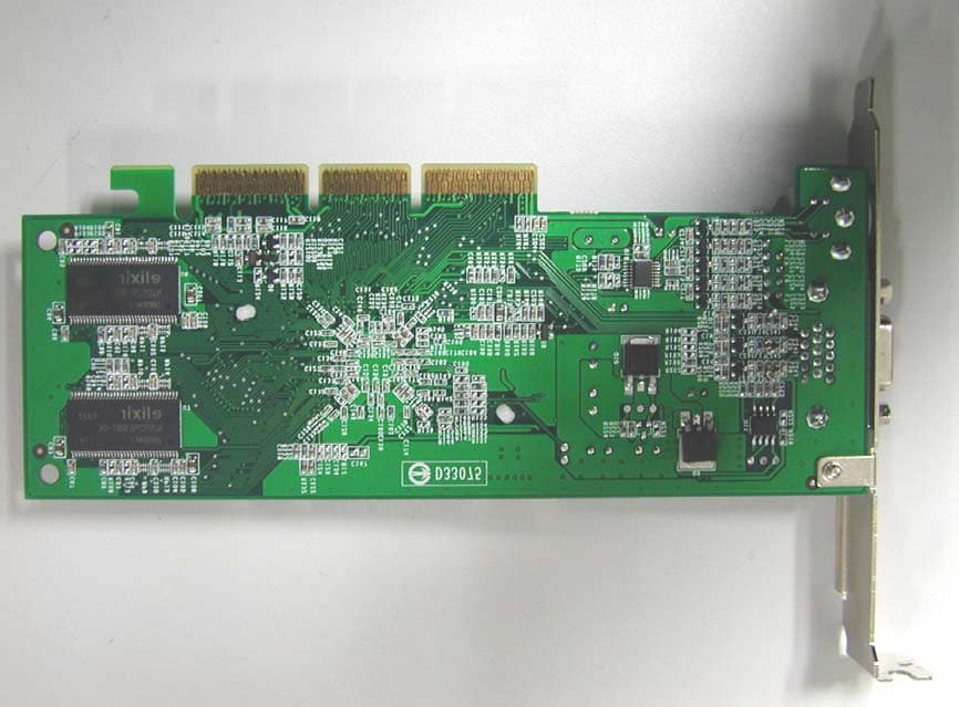
Click to zoom
Application Details
- Equipment Class
- JBP - Part 15 Class B Computing Device Peripheral
- Date of Grant
- Mar 30, 2004
- Application Purpose
- Original Equipment
- Date of Application
- Mar 30, 2004
- Equipment Note
- VGA Card
- Company
- Sparkle Computer Co Ltd
- Country
- Taiwan
Documents & Files
Document Text
Text extracted from the exhibit documents filed with the FCC. Open a document above to read the original.
Users Manual
SP7310 SPARKLE COMPUTER CO., LTD. 3D GRAPHIC ACCELERATOR MANUAL 1.0 1 5.1 Remove old Drivers: (only if you have old nVIDIA drivers) ................................. 7 5.2 Installation and Setup ........................................................................................ 7 5.3 How to Change Color Depth and Resolution in Windows XP ............................. 8 5.4 How to Change Refresh Rate in Windows XP.................................................... 9 5.5 NVIDIA Utility in Windows System ................................................................... 10 5.5.1 GeForce4 MX440−8X (NVIDIA) ............................................................. 10 5.5.2 nView..................................................................................................... 11 5.5.2.1 Standard mode: ........................................................................... 12 5.5.2.2 Color correction... ........................................................................ 13 5.5.2.3 Screen Adjustment... ................................................................... 14 5.5.2.4 Display Timing............................................................................. 14 5.5.2.5 nView enable mode..................................................................... 15 6. Manually install Windows 98 and Windows ME drivers ............................................. 16 6.1 Remove old Drivers: (only if you have old nVIDIA drivers) ............................... 16 6.2 Installation and Setup ...................................................................................... 16 6.3 How to Change Color Depth and Resolution.................................................... 17 6.4 How to Change Refresh Rate.......................................................................... 17 7. Manually install Windows 2000 drivers ..................................................................... 18 FCC Statement............................................................................................................. 19 Warning: ................................................................................................................ 19 Trademark Acknowledgments ...................................................................................... 19 2 including Z occlusion culling, fast Z clear, and auto precharge – effectively multiplies the memory bandwidth to ensure fluid frame rates for the latest 3D and 2D games and applications MX Memory Crossbar Dual memory controllers allow more efficient utilization of memory bandwidth Integrated Dual 350MHz DACs Drivers two independent CRT display with crisp and clear image quality at 1600x1200 resolution (2 CRT output is optional function) Integrated TV Encoder supporting 1024x768 Resolution Provides best-in-class TV-out functionality (optional) Accuview Antialiasing Delivers unprecedented AA performance and quality to the mainstream market and enables high resolution, high frame rate, full-scene antialiasing for the first time ever in this market segment Video Processing Engine (VPE) Enables the highest quality, full-frame rate, full-screen HDTV and DVD without requiring a high performance CPU AGP 8X/4X/2X with AGP Texturing and Fast Writes AGP 8X is the highest performance connection between the CPU and graphics processor. Taking advantage of new methods for transferring information more efficiently allows content developers to use high-quality 32-bit color textures and high-polygon count scenes. Other Features 2 dual-rendering pipelines 4 texels per clock cycle Cube environment mapping 64MB/128MB high-speed 128-bit DDR RAM memory High-performance 2D rendering engine NVIDIA Shading Rasterizer AGP Fast write and AGP Texturing Support Integrated hardware transform engine Integrated hardware lighting engine 3 OpenGL 1.3 and lower DirectX 8.1 and lower 2. Hardware installation 2.1 Package Contents 1. NVIDIA GeForce4 MX440−8X/MX4000 3D Accelerator card 2. Drivers CD title 3. This manual 4. Accessories See appendix for accessories detail and connection topology. 2.2 Installing the card 1. Turn off your computer 2. Remove the cover of the computer per the owner’s manual 3. Install the card in the AGP bus slots 4. Replace the cover. 4 1024*768 16 60/70/72/75/85/100/120/140/144/150/170/200/240 32 60/70/72/75/85/100/120/140/144/150/170/200 8 60/70/72/75/85/100/120/140/144/150/170/200 1152*864 16 60/70/72/75/85/100/120/140/144/150/170/200 32 60/70/72/75/85/100/120/140/144/150 8 60/70/72/75/85/100/120/140/144/150/170 1280*960 16 60/70/72/75/85/100/120/140/144/150/170 32 60/70/72/75/85/100/120/140/144/150 8 60/70/72/75/85/100/120/140/144/150/170 1280*1024 16 60/70/72/75/85/100/120/140/144/150/170 32 60/70/72/75/85/100/120/140/144/150 8 60/70/72/75/85/100/120/140/144/150 1600*900 16 60/70/72/75/85/100/120/140/144/150 32 60/70/72/75/85/100/120 8 60/70/72/75/85/100/120 1600*1200 16 60/70/72/75/85/100/120 32 60/70/72/75/85/100 Different driver version or different windows platform may have different support table. 5 4.3 Click Driver installation 4.4 If everything fine, screen will show Confirm Installation window. Then Select OK 6 If the drivers is very new may not be certified by Microsoft, if so, system will prompt you the drivers do not have “digital signature”, still you can force to install. 4.6 Then click “Yes” to restart your computer. 7 4. Double-click on the Display icon in the Control Panel folder. You can also click the right mouse button anywhere on the desktop and select the Properties option form the pop-out menu. 5. Click Settings , and then Advanced 6. Now shows [Plug And Play Monitor and NVIDIA...] window Select Adapter 7. Then show Standard PCI Graphics...(or NVIDIA GeForce...) Select Properties 8. Then show Adapter Properties ... Select Driver and click Update driver... 9. Then show Hardware Update Wizard Select Install from a list or specific location (Advanced) – recommended for saving installation time Then select N…
Text truncated - open the document above for the full version.
Block Diagram
SPARKLE SP7310 Block diagram: SP7310 AGP BUS Memory BIOS Nvidia GeForce MX4000 CRT Monitor X’TAL 27.0MHZ TV
External Photos
NEUTRON EMC LAB. Project No.:04E0124 2/3 04E0124 04E0124 NEUTRON EMC LAB. Project No.:04E0124 3/3 04E0124
ID Label/Location Info
FCC ID: M697310
ID Label/Location Info
-- FCC ID label -- The remained portion of label statement required by FCC is attached in the user’s manual. -- Location of Label on EUT -- 4cm 0.5cm FCC ID: M697310 FCC ID: M697310
Internal Photos
NEUTRON EMC LAB. Project No.:04E0124 2/3 04E0124 04E0124 NEUTRON EMC LAB. Project No.:04E0124 3/3 04E0124
Test Report
NEUTRON EMC LAB. Report No.:NEI- FCC-E-04039 2/26 Declaration Neutron represents to the client that testing is done in accordance with standard procedures as applicable and that test instruments used has been calibrated with the standards traceable to National Measurement Laboratory (NML) of R.O.C., or National Institute of Standards and Technology (NIST) of U.S.A. Neutron's reports apply only to the specific samples tested under conditions. It is manufacture’s responsibility to ensure that additional production units of this model are manufactured with the identical electrical and mechanical components. Neutron shall have no liability for any declarations , inferences or generalizations drawn by the client or others from Neutron issued reports. Neutron’s reports must not be used by the client to claim product endorsement by the authorities or any agency of the Government. This report is the confidential property of the client. As a mutual protection to the clients, the public and Neutron-self, extracts from the test report shall not be reproduced except in full with Neutron’s authorized written approval. Neutron’s laboratory quality assurance procedures are in compliance with the ISO Guide 17025 requirements, and accredited by the conformity assessment authorities listed in this test report. Limitation For the use of the authority's logo is limited unless the Test Standard(s)/Scope(s)/Item(s) mentioned in this test report is (are) included in the conformity assessment authorities acceptance respective. Assessment Authorities Test Standard/Scope/Item Acceptance FCC Part 15 Subpart B IEC/CISPR22 AS/NZS CISPR 22 CNS 13438 FCC Part 15 Subpart B CISPR 22/EN 55022 AS/NZS CISPR 22 VCCI -Technical Requirement CNS 13438 SS IEC/CISPR 22 IEC/EN 61000-3-2 IEC/EN 61000-4-5 IEC/EN 61000-3-3 IEC/EN 61000-4-6 IEC/EN 61000-4-2 IEC/EN 61000-4-8 IEC/EN 61000-4-3 IEC/EN 61000-4-11 IEC/EN 61000-4-4 CISPR 22/EN 55022 IEC/EN 61000-3-2 IEC/EN 61000-4-5 IEC/EN 61000-3-3 IEC/EN 61000-4-6 IEC/EN 61000-4-2 IEC/EN 61000-4-8 IEC/EN 61000-4-3 IEC/EN 61000-4-11 IEC/EN 61000-4-4 VCCI -Technical Requirement NEUTRON EMC LAB. Report No.:NEI- FCC-E-04039 3/26 Table of Contents Page 1 General Information 5 1.1 Applicant 5 1.2 Manufacturer 5 1.3 Equipment Under Tested 5 1.4 OEM Brand/Model 5 1.5 Model Difference (Series, Versions, if any) 5 1.6 Product Description 6 1.7 Connecting I/O Port(s) 6 1.8 Power Supplied 6 1.9 Products Covered 6 1.10 Description of Test Mode(s) 6 1.11 EUT Modifications 6 1.12 Summary of Test Results 7 2 RFI Emissions Measurement 8 2.1 Test Facility 8 2.2 Standard Compliance 8 2.3 Test Methodology 8 2.4 Deviations from Standard Test Method 8 2.5 Sample(s) Tested 8 2.6 Measurement Instrument 8 2.7 Measurement Uncertainty 9 2.8 Tested System Set-Up/Configuration Details 9 Table -1 Equipments Used in Tested System 10 Diagram -1 Block diagram showing the configuration of system tested 11 Table - 2 Equipments Used in Tested System 12 Table - 3 Information of Interface Cable 12 2.9 EUT Operating Conditions 13 3 Justification 14 3.1 Limitations 14 3.1.1 Power Line Conducted Emission 14 3.1.2 Radiated Emission Limits 14 3.2 Measurement Justification 15 3.2.1 Conducted Emission 15 3.2.2 Radiated Emission 15 3.3 Measurement Data 15 Table 4 Conducted Emission Data 16 Table 5 Radiated Emission Data 19 NEUTRON EMC LAB. Report No.:NEI- FCC-E-04039 4/26 Table of Contents Page Attachment 22 A. EUT Modification Description 23 B. EUT Test Photos 24 NEUTRON EMC LAB. Report No.:NEI- FCC-E-04039 5/26 1. General Information 1.1 Applicant Name SPARKLE COMPUTER CO., LTD. Address 13F, NO. 2, SEC. 1, FU HSING S. RD., TAIPEI, 104 TAIWAN, R.O.C. 1.2 Manufacturer Name N/A Address N/A 1.3 Equipment Under Tested Name: VGA Card Trade Name: SPARKLE Model No.: SP7310; SP7310/128MB; SP7310/64MB 1.4 OEM Brand/Model (if applicable) OEM Brand(s)/Model(s) except the basic model in sub-clause 1.3 is(are) the follows: OEM Brand: N/A Model No.: N/A 1.5 Model Difference (Series, Versions, if any) Except the basic model no. (model designation of the sample tested in this test report), additional model no. covered is(are) : There are three models based on similar electrical circuit except the difference of list below: Model No. DDR SP7310 16X16DDR SP7310/128MB 16X16DDR SP7310/64MB 8X16DDR All the above models were tested, and the model: SP7310 was found to be the worst case during the pr-scanning test. This mode of the worst case was used for final testing and collecting test data included in this report. NEUTRON EMC LAB. Report No.:NEI- FCC-E-04039 6/26 1.6 Product Descriptions(Application/Features/Specification) The EUT is a VGA Card. Based on the application, features, or specification exhibited in User's Manual, the EUT is considered as an ITE/Computing Device. More details of EUT technical specification, please refer to the User's Manual 1.7 Connecting I/O Port(s) Please refer to the User's Manual 1.8 Power Supplied Power Source : Supplied from AGP port. Power Cord : N/A Power Rating : N/A 1.9 Products Covered (if applicable) The sample tested including the following sub-system/module/accessory : Sub-system/ Module/ Accessory Model/Type No. Int. Inst./ Ext. Cont. N/A N/A N/A 1.10 Description of Test Mode(s) To investigate the maximum EMI emission characteristics generates from EUT, the test system was pre-scanning tested base on the consideration of following EUT operation mode or test configuration mode which possible have effect on EMI emission level. Each of these EUT operation mode(s) or test configuration mode(s) mentioned above was evaluated respectively. Mode 1 1600*1200/106KHz/85Hz and S-Video (CRT & TV) Mode 2 1024*768/99KHz/120Hz and S-Video (CRT & TV) Mode 3 800*600/91KHz/140Hz and S-Video (CRT & TV) The EUT system operated Mode 1, 2, and 3, mentioned above were found to be the worst case during the pre-scanning test. These operation modes were used for final testing and collecting test data included in this report. 1.11 EUT Mod…
Text truncated - open the document above for the full version.
Test Setup Photos
NEUTRON EMC LAB. Report No.:NEI- FCC-E-04039 25/26 Conducted Measurement Photos NEUTRON EMC LAB. Report No.:NEI- FCC-E-04039 26/26 Radiated Measurement Photos
Contact Information
Applicant
Jack Hsiao(Manager)
886 2 2741-1196Fax: 886 2 2711-7692
Test Firm
Neutron Engineering Inc.George Yao
Technical Specifications
| # | Rule Parts | Frequency Range | Power Output |
|---|---|---|---|
| 1 | 15B | - | - |
Other Applications from Sparkle Computer Co Ltd
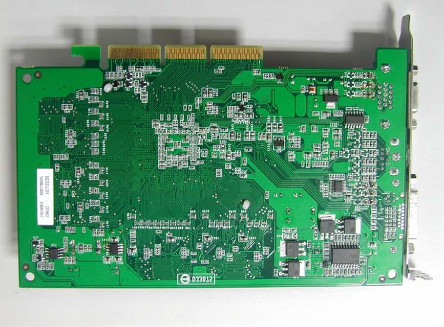
M698836
Apr 14, 2004VGA Card
Equipment Class
JBP - Part 15 Class B Computing Device Peripheral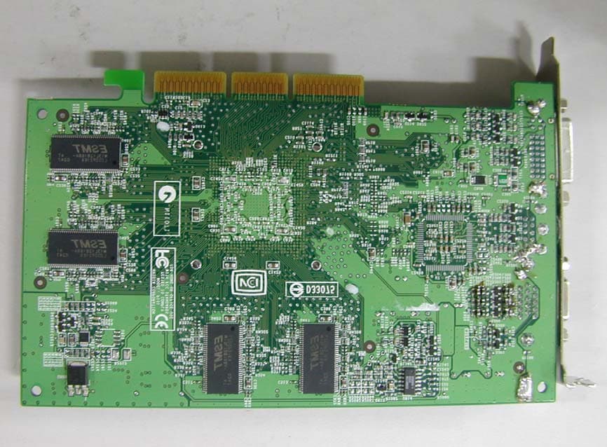
M697228T2
Feb 04, 2003VGA Card
Equipment Class
JBP - Part 15 Class B Computing Device Peripheral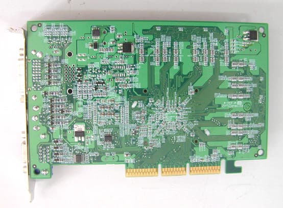
M697300M4
Feb 04, 2003VGA Card
Equipment Class
JBP - Part 15 Class B Computing Device Peripheral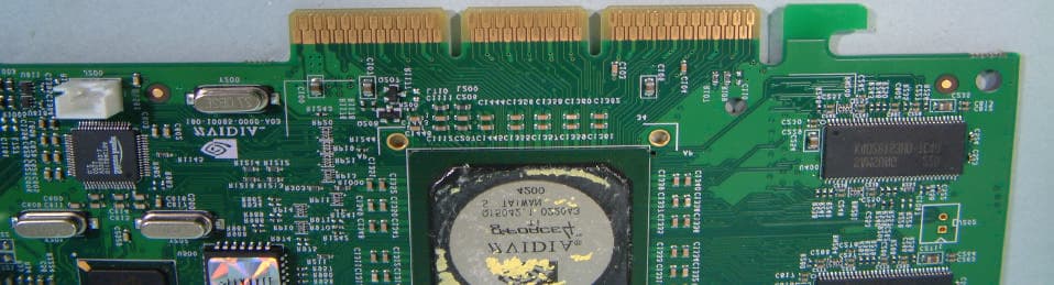
M697200T2
Dec 30, 2002VGA Card
Equipment Class
JBP - Part 15 Class B Computing Device Peripheral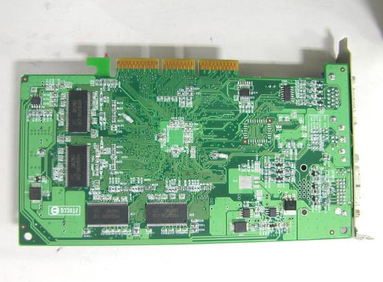
M697100A3
Nov 21, 2002VGA Card
Equipment Class
JBP - Part 15 Class B Computing Device Peripheral