M74-6863Table Tracker
Long Range Solutions, LLC
Click to zoom
Application Details
- Equipment Class
- DTS - Digital Transmission System
- Date of Grant
- Dec 13, 2012
- Application Purpose
- Original Equipment
- Date of Application
- Dec 13, 2012
- Equipment Note
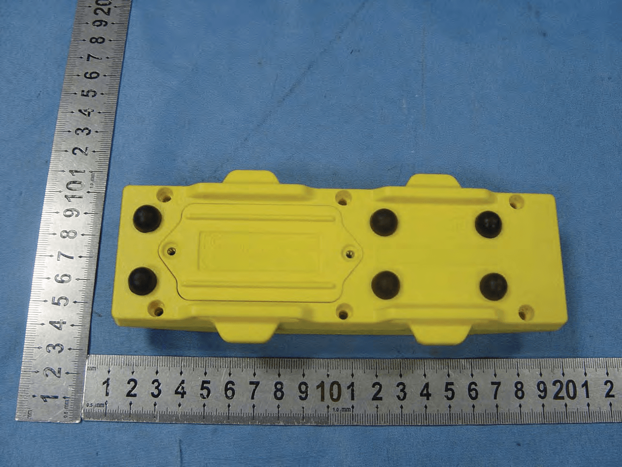
- Table Tracker
- Frequency Range
- 2405.00000000 - 2480.00000000
- Company
- Long Range Solutions, LLC
- Country
- United States
Documents & Files
Document Text
Text extracted from the exhibit documents filed with the FCC. Open a document above to read the original.
Users Manual
Installation, Wa rranty and Service Information Long Range Systems, Inc. 4550 Excel Parkway, Suite 200 Addison, TX 75001 800.437.4996 • www.pager.net Table Tracker USER MANUAL Table Of Contents Installation and Setup . . . . . . . . . . . . . . . . . . . . . . . . . . . . . . . . . . . . . . . . . . . . 2 Basic Installation . . . . . . . . . . . . . . . . . . . . . . . . . . . . . . . . . . . . . . . . . . . . . . . . . . . . . 2 Table Tracker . . . . . . . . . . . . . . . . . . . . . . . . . . . . . . . . . . . . . . . . . . . . . . . . . . . 3 Basic Operation . . . . . . . . . . . . . . . . . . . . . . . . . . . . . . . . . . . . . . . . . . . . . . . . . . . . . . 3 Using the Table Tracker . . . . . . . . . . . . . . . . . . . . . . . . . . . . . . . . . . . . . . . . . . . . . . . . 3 Table Tracker Monitor . . . . . . . . . . . . . . . . . . . . . . . . . . . . . . . . . . . . . . . . . . . . . . . . . 4 Configuration Settings . . . . . . . . . . . . . . . . . . . . . . . . . . . . . . . . . . . . . . . . . . . . . . . . . 5 Service Questions and Answers . . . . . . . . . . . . . . . . . . . . . . . . . . . . . . . . . . . . .10 Warranty . . . . . . . . . . . . . . . . . . . . . . . . . . . . . . . . . . . . . . . . . . . . . . . . . . . . . . .11 Long Range Systems1Table Tracker User Manual INSTALLATION AND SETUP Basic Installation 1. Unpackage all system components. - All-in-one PC - 2.4GHz USB Antenna - Table Trackers - Table Tracker Charger(s) - Starter Unit(s) - Clearing Unit(s) 2. Setup All-In-One PC Monitor in the expeditor area 3. Plug the 2.4 GHz USB Antenna into a USB Port on the All-In-One PC 4. Power on PC - using the surge protector provided 5. Plug in the Table Tracker Charger(s) (usually placed by the cash register) 6. Place Table Trackers on Charger 7. Place Starter Unit(s) by the cash register 8. Place Clearing Unit(s) by the food expedite area Status LED Charge Pin Number Heartbeat LED Table Tracker Stacked Charging Long Range Systems2Table Tracker User Manual Table Tracker Basic Operation 1. The Cashier taking orders should ALWAYS place each Table Tracker on the Starter Unit before handing them out to ensure the timer is started on the touch screen PC. This will ensure the ac- curacy of your reports. When handing the unit to the customer, the cashier must explain to the customer that the Table Tracker units must be placed on the table where they will be sitting. 2. The customer takes the Table Tracker and lays it on any available table. 3. The Table number appears next to the order number on the touch-screen monitor. 4. When the food order is ready, the runner takes the order to the table on the screen. 5. The runner picks up the Table Tracker, returns to the food service area, and places it on the Clear- ing Unit to clear the order from the touch-screen PC and complete the cycle. 6. Table Trackers are taken back to the cashier throughout the shift Using the Table Tracker Starter Unit The Starter Unit is located near the cashier or starting point of a transaction. After an order is placed, the Table Tracker is held over the Starter Unit. The status LED will flash green for 2 seconds, and then the timer will start on the all in one PC monitor. The customer will head for a table. Clearing Unit When the order has been delivered, hold the Table Tracker over the Clearing Unit. The status LED will flash green for 2 seconds and then the timer will clear from the all in one PC monitor. RFID Tags and Mats RFID Tags and Mats, available from LRS, are programmed with the appropriate Table Number so when a guest sits down with their order number, the Table Tracker will detect a RFID Tag under the table (ex:10) and the Table Number will appear with the order number on the screen. Long Range Systems3Table Tracker User Manual Table Tracker Monitor Main Display - All in One PC/Monitor This will display the • Order number given to the customer. • Table that the Order number is currently located. • The amount of time elapsed since order started. Displays Today’s Score This indicates the daily percentage of orders successfully delivered within the secured preset timers. Average Time This indicates the average time it takes to process orders. Exiting the Program To Exit the PC Program, press the Power Symbol in the bottom right corner of the screen. Long Range Systems4Table Tracker User Manual Long Range Systems5Table Tracker User Manual When switching to the Configuration or Reports Menus, the user is required to enter a Managers Access Code. The standard access code is 5-6-7-8-9. To Cancel access at any time, press the button. To edit an entry, press the button. Configuration Settings System Menu UHF System ID This is a unique ID of the transmitter that allows paging messages between the host transmitter and staff pagers. Group Paging Enables or disables group paging. Online Reporting Enables or disables online reporting. DB Backup Creates a backup for the current Database on the PC. Change Language This option allows the user to switch the currently displayed language between English, Polish, and Spanish. Orders Settings Number of Columns Varies the number of columns on the Orders Screen from 1 to 5 Auto Clear Enables or disables an order automatically clearing from the screen after a set time. If enabled, the user can enter a time (in minutes) to set when the order will clear. Order Clear Requires Password This feature allows if the user attempts to clear an order manually from the screen, they are required to type in the Manager’s Password. Week Start Day This sets the starting day for reporting purposes as Monday through Sunday. Enable Paging Allows for paging of Table Trackers from the orders screen. Long Range Systems6Table Tracker User Manual Long Range Systems7Table Tracker User Manual Interval Timing Interval Time is the time that is considered acceptable for order deliveries. Using the 1st Warning Time and 2nd Warning Times, the Table Tracker Monitor can display how long an…
Text truncated - open the document above for the full version.
Attestation Statements
Long Range Systems Inc Nov 23, 2012 To: Federal Communications Commission Authorization and Evaluation Division 7435 Oakland Mills Road Columbia, MD FCC ID: M74-6863 To Whom It May Concern: This letter is to ascertain that Long Range Systems Inc (Product:Table Tracker Model name: 6863) has been the units used for conducting FCC compliance testing, the DoC part will be tested by FCC recognized test lab. If you have any question or concerns, pls. contact us.
Cover Letter(s)
Long Range Systems Inc Nov 23, 2012 To: SIEMIC, INC. 775 Montague Expressway Milpitas, CA 95035 USA Dear Sir/Madam, Re: Project and Product Certification Representative Authorization Letter We, ______Long Range Systems Inc ___hereby authorize SIEMIC, INC. to act as a Certification Body for certifying for the following project(s): Product Description: Table Tracker Model name: 6863 FCC ID: M74-6863 We affirm that between SIEMIC and _ Long Range Systems Inc __, any difference in understanding, including test plan, measurement methods, applicable standards and relevant procedures and processes have been resolved prior to commencement of testing activities. Sincerely, Client’s signature: Client’s name / title: Kenneth / President Contact information / address: 4550 Excel Parkway #200, Addsion, Texas, 75001, United States
Cover Letter(s)
SCS-F19: Confidentiality Request Letter Page 1 of 2 Rev 3.0 775 Montague Expressway Milpitas, CA 95035 Tel: 408-526-1188 Fax: 408-526-1088 Email: [email protected] Confidentiality Request Letter Revision History Reason for Amendment (current / obsolete) From To Approved Date Initial Release (obsolete) 1.0 1.0 Nov-14-2006 Adding CFR 2.459 (obsolete) 1.0 2.0 August – 11 - 2008 Updated company template & Added text box (current) 2.0 3.0 Jan-31-2012 SCS-F19: Confidentiality Request Letter Page 2 of 2 Rev 3.0 Long Range Systems Inc Nov 23, 2012 To: Federal Communications Commission Authorization and Evaluation Division 7435 Oakland Mills Road Columbia, MD Subject: Permanent Confidentiality Request for FCC ID: M74-6863 We hereby request confidential treatment of information accompanying this application as outlined below: - Block Diagram - Schematics - Operational Description The above materials contain trade secrets and proprietary information not customarily released to the public. The public disclosure of these materials may be harmful to the applicant and provide unjustified benefits to its competitors. The applicant understands that pursuant to Section 0.457 & 0.459 of the Rules, disclosure of this application and all accompanying documentation will not be made before the date of the Grant for this application.
ID Label/Location Info
Long Range Systems Table Tracker FCC ID: M74-6863 MODEL: 6863 This device complies with Part 15 of FCC rules. Operation is subject to the following two conditions: (1) This device may not cause interference, and (2) This device must accept any interference, including interference that may cause undesired operation of the device
ID Label/Location Info
Label Location
Internal Photos
Antenna for Zigbee Antenna for Zigbee
RF Exposure Info
FCC ID : M74-6863 Portable device According to §15.247(e)(i) and §1.1307(b)(1), systems operating under the provisions of this section shall be operated in a manner that ensures that the public is not exposed to radio frequency energy level in excess of the Commission’s guidelines. According to KDB 447498 (2)(a)(i) Frequency Range Low Frequency (MHz) High Frequency(MHz) Maximum measured transmitter power frequency (MHz) 60/f SAR Limitation (mW) 2405 2480 2405 24.9 Maximum measured transmitter power Conducted Power (mw) Max Antenna Gain (dBi) EIRP (mW) 0.56 0 0.56 Remark: The best case gain of the antenna is 0dBi. 0dBi logarithmic terms convert to numeric result is nearly 1 According to the formula. calculate the EIRP test result: EIRP= P x G = 0.56 x 1 = 0.56 Threshold at which no SAR required is 24.9mW. Maximum TX power is 0.56mw. Conclusion: No SAR is required. SIMULTANEOUS TRANSMISSION EVALUATION N/A
Test Report
Page 1 of 69 FCC ID: M74-6863 ACCURATE TECHNOLOGY CO., LTD Report No.: ATE20121266 APPLICATION CERTIFICATION FCC Part 15C On Behalf of Long Range Systems Inc Table Tracker Model No.:6863 FCC ID: M74-6863 Prepared for : Long Range Systems Inc Address : 4550 Excel Parkway #200, Addsion, Texas, 75001, United States Prepared by : ACCURATE TECHNOLOGY CO., LTD Address : F1, Bldg. A, Chan Yuan New Material Port, Keyuan Rd. Science & Industry Park, Nan Shan, Shenzhen, Guangdong P.R. China Tel: (0755) 26503290 Fax: (0755) 26503396 Report Number : ATE20121266 Date of Test : Jun 11- Oct 28, 2012 Date of Report : Oct 28, 2012 Page 2 of 69 FCC ID: M74-6863 ACCURATE TECHNOLOGY CO., LTD Report No.: ATE20121266 TABLE OF CONTENTS Description Page Test Report Certification 1. GENERAL INFORMATION .......................................................................................................... 5 1.1. Description of Device (EUT)....................................................................................................................5 1.2. Carrier Frequency of Channels .................................................................................................................6 1.3. Special Accessory and Auxiliary Equipment ...........................................................................................6 1.4. Description of Test Facility ......................................................................................................................7 1.5. Measurement Uncertainty.........................................................................................................................7 2. MEASURING DEVICE AND TEST EQUIPMENT ..................................................................... 8 3. OPERATION OF EUT DURING TESTING ................................................................................. 9 3.1. Operating Mode ........................................................................................................................................9 3.2. Configuration and peripherals ................................................................................................................10 4. TEST PROCEDURES AND RESULTS ....................................................................................... 11 5. 6DB BANDWIDTH MEASUREMENT ........................................................................................ 12 5.1. Block Diagram of Test Setup..................................................................................................................12 5.2. The Requirement For Section 15.247(a)(2) ............................................................................................12 5.3. EUT Configuration on Measurement .....................................................................................................12 5.4. Operating Condition of EUT ..................................................................................................................12 5.5. Test Procedure ........................................................................................................................................13 5.6. Test Result ..............................................................................................................................................13 6. MAXIMUM PEAK OUTPUT POWER ....................................................................................... 17 6.1. Block Diagram of Test Setup..................................................................................................................17 6.2. The Requirement For Section 15.247(b)(3)............................................................................................17 6.3. EUT Configuration on Measurement .....................................................................................................17 6.4. Operating Condition of EUT ..................................................................................................................17 6.5. Test Procedure ........................................................................................................................................18 6.6. Test Result ..............................................................................................................................................18 7. POWER SPECTRAL DENSITY MEASUREMENT.................................................................. 22 7.1. Block Diagram of Test Setup..................................................................................................................22 7.2. The Requirement For Section 15.247(e).................................................................................................22 7.3. EUT Configuration on Measurement .....................................................................................................22 7.4. Operating Condition of EUT ..................................................................................................................22 7.5. Test Procedure ........................................................................................................................................23 7.6. Test Result ..............................................................................................................................................23 8. BAND EDGE COMPLIANCE TEST ........................................................................................... 27 8.1. Block Diagram of Test Setup..................................................................................................................27 8.2. The Requirement For Section 15.247(d) ................................................................................................27 8.3. EUT Configuration on Measurement .....................................................................................................27 8.4. Operating Condition of EUT ......................................................…
Text truncated - open the document above for the full version.
Contact Information
Applicant
Robert Pinell
Test Firm
Accurate Technology Co., Ltd.Sean Liu
Technical Specifications
| # | Rule Parts | Frequency Range | Power Output |
|---|---|---|---|
| 1 | 15C | 2.40 GHz - 2.48 GHz | 560.00 µW |
Other Applications from Long Range Solutions, LLC
M745629
May 10, 2012Beach Bulter xp
Equipment Class
DSC - Part 15 Security/Remote Control Transmitter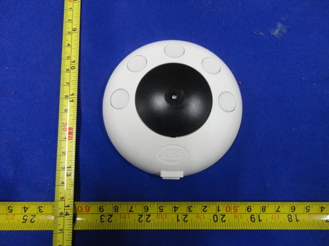
M74PRONTO
Feb 12, 2012PRONTO
Equipment Class
DSC - Part 15 Security/Remote Control Transmitter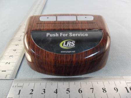
M74TGUHF
Jul 20, 2011Table Genie UHF
Equipment Class
DSC - Part 15 Security/Remote Control Transmitter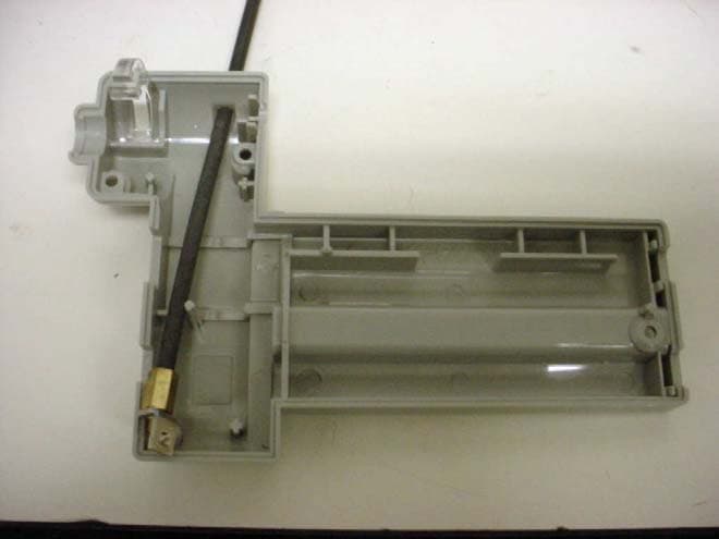
M74T1505
Mar 24, 2004Wireless Low Power Medical Paging Transmitter
Equipment Class
DSC - Part 15 Security/Remote Control Transmitter
M74T7400
Mar 23, 2000On Site Pager
Equipment Class
TNB - Licensed Non-Broadcast Station Transmitter