M74T1505Wireless Low Power Medical Paging Transmitter
Long Range Solutions, LLC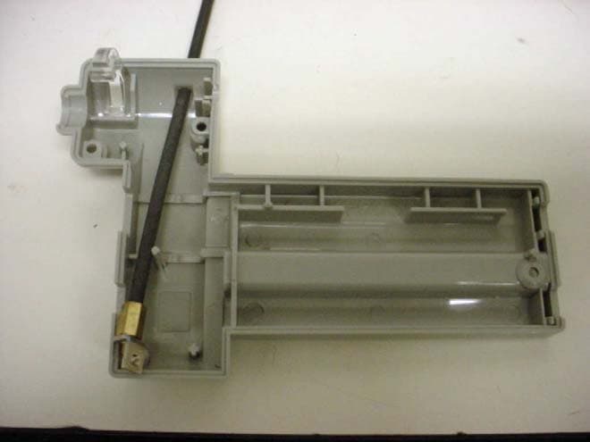
Click to zoom
Application Details
- Equipment Class
- DSC - Part 15 Security/Remote Control Transmitter
- Date of Grant
- Mar 24, 2004
- Application Purpose
- Original Equipment
- Date of Application
- Mar 24, 2004
- Equipment Note
- Wireless Low Power Medical Paging Transmitter
- Frequency Range
- 467.75000000 - 467.75000000
- Company
- Long Range Solutions, LLC
- Country
- United States
Documents & Files
Document Text
Text extracted from the exhibit documents filed with the FCC. Open a document above to read the original.
Users Manual
Posey Sitter II Wireless Nurse Call User Manual Installation, Warranty, and Service Information J. T. Posey Company 5635 Peck Rd., Arcadia, CA 91006-0020 TEL. 800-44-POSEY – 626-443-3143 – FAX 800-767-3933 www.posey.com Sitter II 1 Posey Sitter II Alert and Staff Paging TABLE OF CONTENTS Warranty ................................................................................ 1 General Information ............................................................. 2 Installation and Setup .......................................................... 2 Installation Procedure.......................................................................................................................................2 Installation Checklist.........................................................................................................................................2 Basic Operating Instructions ............................................................................................................................3 Programming ........................................................................ 3 Basic Procedure ...............................................................................................................................................3 Programming Screen .......................................................................................................................................3 Programming Pagers .......................................................................................................................................4 Sitter II Specifications .......................................................... 5 Power and Frequency Specification.................................................................................................................5 Service Questions and Answers......................................... 5 My System is malfunctioning - What do I do? ..................................................................................................5 What about repairing my system after the warranty expires? ..........................................................................5 Ordering Additional Pagers ..............................................................................................................................5 WARRANTY TBD Sitter II 2 GENERAL INFORMATION The Sitter II is a multi-purpose on-premise paging system. This unit plugs into an existing Posey alert system to provide secondary alert to the main hard wire system The pass through security contact alerts a staff pager of a call to the nurse station. A test push button is available ensures the system operation and also is used as a page acknowledged button. Built in rechargeable batteries ensure operation in event of power outage. The unit can be individually programmed to provide call location and time. The pagers used with the system can vibrate, beep and display stored messages. INSTALLATION AND SETUP Installation Procedure The following is the basic installation procedure. Systems are set for the most general use. If you have specific changes, refer to the appropriate section of this manual. 1. Unwrap all Sitter II components. 2. The following items are included with this unit. 1 – Sitter II Transmitter 1 – Software CD 1 – Programming Cable 1 – 7.5 VDC Charging adapter 1 – Programming Booklet 3. Connect the 7.5 VDC adapter to the Sitter II 4. Install the Sitter II programming software on your computer. 5. Connect the programming cable from your computer to the connector on the side of the Sitter II. 6. Program the contact switch input to page the desired pager(s). 7. Mount the Sitter II into the Posey Alarm station where desired. 8. Press the test button to test the system (transmitter and pager(s). 9. The system is ready for operation. Installation Checklist When Installing the Sitter II: Be sure the Sitter II is programmed the way you want it. Mount the Sitter II where you want it and connect the battery charger. Press the “Test” button (twice) and be sure your pager receives the message. Test the detector and be sure the pager receives the right message. STAFF PAGER 7.5-VDC CHARGER INPUT SERIAL PROGRAMMING CABLE DETECTOR ALARM INPUT PASS THROUGH ALARM OUTPUT PROGRAMMING PC PROGRAMMING CONNECTOR PATIENT NEEDS ASSISTANC TEST AND PAGE ACKNOWLEDGE BUTTON ALARM INDICATOR Sitter II 3 Basic Operating Instructions Connect the Sitter II to your computer and set the security sensor input to page your pager(s). When the sensor is activated, your pagers will be called. Some possibilities are (see your programming instruction): PROGRAMMING Basic Procedure Note: Systems are not programmed when shipped. The following describes the basic programming procedure. 1. Install the Sitter II programming software on your computer. 2. Start the program. 3. Connect the 7.5 VDC battery charger to the Sitter II. 4. Connect the programming cable from the computer serial port to the Sitter II programming connector. 5. At the programming screen, select the COM port used (usually COM 1). 6. Program the sensor switch input to page the desired pager(s) with the desired information. 7. After the functions are set, press the Update Unit button to load the Sitter II. 8. When finished, install the Sitter II where you will use it and put it into service. Programming Screen The Programming Screen controls all the functions loaded into the Sitter II and programming of pagers. Posey Commands Section Update Unit – Loads the functions set on the screen into the Sitter II. Set Pager Time – Used to send the current time and date to the numeric pagers. Read Unit – Polls the Sitter II and displays its current functions. Pgm Pagers – If on air programmable pagers are used, this enables a screen to program them with the Sitter II. Global Settings Section Serial Num: – This is the serial number retrieved from the unit being programmed (not input by user). Sys ID: - This is the identif…
Text truncated - open the document above for the full version.
Block Diagram
Exhibit H: Block Diagram Long Range Systems T1505 Transmitter 20 20 19 19 18 18 17 17 16 16 15 15 14 14 13 13 12 12 11 11 10 10 9 9 8 8 7 7 6 6 5 5 4 4 3 3 2 2 1 1 TT SS RR QQ PP OO NN MM LL KK JJ II HH GG FF EE DD CC BB AA Sheet Sheet Revision Board revision date : Board Board Revision 9855 Chartwell Dr. Dallas, Texas 75243 www.pager.net (214)553-5308 LRS Part# Sheet revision date : Long Range Systems, Inc. A A 4 1 BLOCK DIAGRAM POSEY 4-23-20034-23-2003 <Alliance_Num> RS232 INTERFACE SENSOR INPUT SW JACK, SW PLUG BUTTON PAGE 2 PAGE 2 PAGE 4 PAGE 3 PAGE 2 PAGE 3 PROCESSOR SYSTEM RF TRANSMITTER BATTERY CHARGER INPUT POWER DC-DC Converter 200KHz switching Freq. DC Input 7.5V 200MA Atmel ATMEGA128 3.6864MHz Crystal Oscillator RS232 Interface 9600 Baud Ref. Xtal Oscillator 14.6178MHz LC TANK PLL L.O. 32X Ref. F=467.750MHz RF Out F=467.750MHz Digital Modulation 1200 Hz System Power 7.5VDC Processor Power 5VDC System Power 7.5VDC FSK Modulation +-4.5KHz
Cover Letter(s)
Exhibit G: Letter of Authorization Long Range Systems T1505 Transmitter LRS Long Range Systems, Inc. 9855 Chartwell Dr, Dallas, Texas 75243 (214) 553-5308 FAX: (214) 221-0160 www.pager.net Thursday, August 21, 2003 American Telecommunications Certification Body, Inc. 6731 Whitter Avenue Suite C110 McLean, VA 22101 To Whom It May Concern: Please be advised that Long Range Systems, Inc. (LRS) authorizes Professional Testing (EMI), Inc. to act on our behalf, until otherwise notified, for applications submitted to American Telecommunications Certification Body, Inc. (ATCB) We certify that we are not subject to denial of federal benefits, that includes FCC benefits, pursuant to Section 5301 of the Anti-Drug Abuse ACT of 1988, U.S.C. 862. Further, no party, as defined in 47 CFR 1.2002(b), to the application is subject to denial of federal benefits, that includes FCC benefits. Thank you for your attention to this matter. Russell Blink
Cover Letter(s)
American Telecommunications Certification Body Inc. 6731 Whittier Ave, McLean, VA 22101 March 23, 2004 RE: Long Range Systems FCC ID: M74T1505 I have a few comments on this Application. 1.) Please confirm if the Schematics, Block Diagram, Parts List and Operational Description should be held Confidential. If so, then kindly upload the appropriate Confidentiality Request letter. 2.) The field strength limit for 467.75 MHz appears to be incorrect. Part 15.231 limits at this frequency by my calculations are 12,358uV. Please correct your Test Report. Harmonics are 20dB down from this level, for a level of 1,236uV. 3.) Please explain why there are two limits given for radiated emission measurements above 1GHz. I note that testing was performed at 1M per your explanation on pp.6 of 18, but I am still confused on the use of 71.4 and 63.5 dBuV. 4.) Please also note that some emissions fall within the Restricted Bands of 15.205. Please show compliance with this band to the 10 th harmonic. 5.) In general, all emissions above 1GHz should be measured in both Peak and Average modes per ANSI C63.4. Please provide Peak and Average data. 6.) FYI: Please note that “worst case” radiated emissions for the fundamental do not necessarily predict worst case radiated on the harmonics. Please review your test procedure. Regards, William H. Graff President and Director of Engineering mailto: [email protected] The items indicated above must be submitted before processing can continue on the above referenced application. Failure to provide the requested information may result in application termination. Correspondence should be considered part of the permanent submission and may be viewed from the Internet after a Grant of Equipment Authorization is issued. Please do not respond to this correspondence using the email reply button. In order for your response to be processed expeditiously, you must submit your documents through the AmericanTCB.com website. Also, please note that partial responses increase processing time and should not be submitted. Any questions about the content of this correspondence should be directed to the sender.
Cover Letter(s)
American Telecommunications Certification Body Inc. 6731 Whittier Ave, McLean, VA 22101 November 5, 2003 RE: Long Range Systems FCC ID: M74T1505 I have a few comments on this Application. 1.) No External Photographs were uploaded with this filing. Please provide. 2.) External Photographs must also show equipment with no RF shielding. Please remove copper tape. 3.) External photographs are also too small to be useful. Please supply larger and clearer photos. Please indicate the location of the antennas. 4.) If copper tape is to be used for the shielding of all production products, please provide attestation. If copper tape was added during testing, it should be noted in the report. 5.) Please provide information as to the content of the transmitted intelligence in the POSCAG emission. 6.) The Block Diagram contains too few details. Please review 2.1033(b)(5). Please note our main concern is of the RF portion of this device. 7.) Please indicate which sheet of schematics contains the RF portion of the transmitter. 8.) Your radiated test results show a comparison between Quasi-Peak and Average. This is incorrect for 15.231. You should be comparing Peak and Average. See 15.35(c) and 15.31. Please review your measurements. 9.) In addition. You should be providing test information for all the timing information required under 15.231(1), 15.231(2). 10.) The HP 8568 listed in your equipment list is specified by the manufacturer [HP Test and Measurement Catalog, 1994] to just 1500MHz. Please explain how data was taken to the 10 th harmonic (4.7GHz). 11.) The Operational Description indicates this equipment operates on 12.5 KHz channel spacing. But the Form 731 seems to indicate that only a single channel is used. What is the frequency range of this device? Please be mindful that the requirements of 15.31(m) may affect the number of channels selected for measurement. 12.) No confidentiality request letter was uploaded with the filing. Are their no Confidential exhibits? 13.) Please note that for all Part 15 Certifications, a Parts List is not required but as an option can be supplied. Do you wish for the Parts List to be posted to the FCC website? 14.) The Manual indicates this is a .25W transmitter. This is easily in excess of the limits for 15.231. Please revise. William H. Graff President and Examining Engineer mailto: [email protected] The items indicated above must be submitted before processing can continue on the above referenced application. Failure to provide the requested information may result in application termination. z Page 2 November 5, 2003 Correspondence should be considered part of the permanent submission and may be viewed from the Internet after a Grant of Equipment Authorization is issued. Please do not respond to this correspondence using the email reply button. In order for your response to be processed expeditiously, you must submit your documents through the AmericanTCB.com website. Also, please note that partial responses increase processing time and should not be submitted. Any questions about the content of this correspondence should be directed to the sender.
Cover Letter(s)
From: Michael Royer [[email protected]] Sent: Wednesday, March 24, 2004 10:25 AM To: [email protected] Cc: David Rahe (E-mail); Jhaley@Ptitest. Com (E-mail); Michelle Cantrell (E-mail); Sree (E-mail) Subject: FW: M74T1504 Comments William, Thank you for your review of the application for Long Range Systems. I have reply comments for your to consider. Item 1. There is no request for confidentiality. Full public disclosure is understood. Item 2. We tabulated the data in logarithmic units. The values are equivalent. 12358 uV/m is the same as 81.9 dBuV/m. (20*log(12358)=81.9) The harmonics are twenty dB down from that at 61.9 dBuV/m. Item 3. The limits at 1m for harmonics is 61.9dBuV/m + 9.5 dB = 71.4. The exception is the restricted band where the general limit is used. The general limit above 1 GHz at 1m. is 63.5 dBuV/m. Item 4. The product was tested up to 5 GHz. No signals were identified above 2.8 GHz. We are sure that there are no signals within 10dB of the the general limit (63.5 dBuV/m). Item 5. We have submitted data collected in peak mode, and established that it meets the more difficult average limits. Data collected with an averaging detector would have even lower levels and would also be compliant. This provision is found in ANSI C63.4 paragraph 8.3.1.2, note 1, Final radiated emissions measurements. Thank you for your consideration of this reply to your comments. It is a pleasure to work with you on this application. Best regards, Mike Royer Michael Royer EMC Engineer Professional Testing (EMI), Inc. 1601 FM 1460 Suite B Round Rock, TX 78660 Ph: (512) 244-3371 ext. 110 Fx: (512) 244-1846 Email: [email protected] --- Outgoing mail is certified Virus Free. Checked by AVG anti-virus system (http://www.grisoft.com). Version: 6.0.572 / Virus Database: 362 - Release Date: 1/27/2004
External Photos
Exhibit E2: EUT Photographs – External Long Range Systems T1505 Transmitter Long Range Systems T1505 Transmitter Case with Antenna Case Empty Long Range Systems T1505 Transmitter External Front View External Rear View
ID Label/Location Info
Exhibit C: Label Artwork Long Range Systems T1505 Transmitter LRS Long Range Systems, Inc. 9855 Chartwell Dr, Dallas, Texas 75243 (214) 553-5308 FAX: (214) 221-0160 www.pager.net Thursday, August 21, 2003 American Telecommunications Certification Body, Inc. 6731 Whitter Avenue Suite C110 McLean, VA 22101 RE: FCC Labeling Requirements FCC ID: M74T1505 To Whom It May Concern: The following label information is required by the FCC Rules and Regulations for certified devices. Also attached, please find marketing information required by the FCC Rules and Regulations. Thank you for your attention to this matter. Russell Blink Label dimensions 0.5” x 1.75” FCC ID: M74T1505 This device complies with Part 15 of the FCC rules. Operation is subject to the following two conditions: (1) this device may not cause harmful interference, and (2) this device must accept any interference received, including interference that may cause undesired operation.
Internal Photos
Exhibit E1: EUT Photographs – Internal Long Range Systems T1505 Transmitter Long Range Systems T1505 Transmitter Circuit Board Internal Circuitry Long Range Systems T1505 Transmitter Internal Circuitry
Operational Description
Exhibit F: Description of Operation Long Range Systems T1505 Transmitter T1505 Transmitter Description: The unit is a low power transmitter that generates NBFM signals to UHF paging receivers The unit transmits with a fixed frequency of 467.750MHz. The modulation rate is maximum of 1200bps. Transmit power is within CFR 47 part 15 limits for intentional radiators. Upon detection of a external switch closure, the unit will transmit a POCSAG encoded signal previously defined using the serial configuration interface. The following summary describes the coding used on POCSAG pager signals. POCSAG POCSAG stands for Post Office Code Standardization Advisory Group. Post office in this context is the British Post Office which used to be the supplier of all telecommunications services in England before privatization. POCSAG as defined in the standard, (original POCSAG) is 512 bits per second direct FSK (not AFSK) of the carrier wave with +- 4.5 khz shift (less deviation than that is used in some US systems). Data is NRZ coded with the higher frequency representing 0 (space) and the lower one representing 1 (mark). The basic unit of data in a POCSAG message is the codeword which is always a 32 bit long entity. The most significant bit of a codeword is transmitted first, followed immediately by the next most significant bit and so forth. The data is NRZ, so that mark and space values (plus and minus voltages) as sampled on the output of the receiver discriminator at a 512 hz rate correspond directly to bits in the codeword starting with the MSB. (Note that the audio output circuitry following the discriminator in a typical voice scanner may considerably distort this square wave pattern of bits, so it is best to take the signal directly off the discriminator before the audio filtering). The first (msb) bit of every POCSAG codeword (bit 31) indicates whether the codeword is an address codeword (pager address) (bit 31 = 0) or a message codeword (bit 31 = 1). The two codeword types have different internal structure. Message codewords (bit 31 = 1) use the 20 bits starting at bit 30 (bit 30-11) as message data. Address codewords (bit 31 = 0) use 18 bits starting at bit 30 as address (bits 30-13) and bits 12 and 11 as function bits which indicate the type and format of the page. Bits 10 through 1 of both types of codewords are the bits of a BCH (31,21) block ECC code computed over the first 31 bits of the codeword, and bit 0 of both codeword types is an even parity bit. The BCH ECC code used provides a 6 bit hamming distance between all valid codewords in the possible set (that is every valid 32 bit codeword differs from ever other one in at least 6 bits). This makes one or two bit error correction of codewords possible, and provides a robust error detection capability (very low chance of false pages). The generating polynomial for the (31,21) BCH code is x**10 + x**9 + x**8 + x**6 + x**5 + x**3 + 1. Codewords are transmitted in groups of 16 (called batches), and each batch is preceded by a special 17th codeword which contains a fixed frame synchronization pattern. Batches of codewords in a transmission are preceded by a start of transmission preamble of reversals (10101010101 pattern) which must be at least 576 bits long. Thus a transmission (paging burst) consists of carrier turn on during which it is modulated with 512 baud reversals (the preamble pattern) followed by at least 576/512 seconds worth of actual preamble, and then a sync codeword (0x7CD215D8), followed by 16 data/address codewords, another sync codeword, 16 more data/address codewords and so forth until the traffic is completely transmitted. As far as known, there is no specified postamble. All 16 of the last codewords of a transmission are always sent before the carrier is shut off, and if there is no message to be sent in them the idle codeword (0x7A89C197) is sent. Later versions of the standard may have modified this however. In order to save on battery power and not require that a pager receive all the bits of an entire transmission (allowing the receiver to be turned off most of the time, even when a message is being transmitted on the channel) a convention for addressing has been incorporated which splits the pager population into 8 groups. Members of each group only pay attention to the two address code words following the synch codeword of a block that correspond to their group. This means that as far as addressing is concerned, the 16 codewords in a batch are divided into 8 frames of two codewords apiece and any given pager pays attention only to the two in the frame to which it assigned. A message to a pager consists of an address codeword in the proper two codeword frame within the batch to match the recipients frame assignment (based on the low three bits of the recipient's 21 bit effective address), and between 0 and n of the immediately following code words which contain the message text. A message is terminated by either another address code word or an idle codeword. Idle codewords have the special hex value of 0x7A89C197. A message with a long text may potentially spill over between two or more 17 codeword batches. Space in a batch between the end of a message in a transmission and either the end of the batch or the start of the next message (which of course can only start in the two correct two codeword frame assigned to the recipient) is filled with idle codewords. A long message which spills between two or more batches does not disrupt the batch structure (sync codeword and 16 data/address code words - sync code word and 16 data/address codewords and so forth) so it is possible for a pager not being addressed to predict when to next listen for its address and only turn on it's receiver then. The early standard text specifies a 21 bit address format for a pager (This has been extended since) with the upper 18 bits of a pager's address mapping into bits 30-13 of the address codeword and the lower 3 bits specifiying which c…
Text truncated - open the document above for the full version.
Parts List/Tune Up Info
Exhibit J: Bill of Materials Long Range Systems T1505 Transmitter ItemQTYPart #DescriptionMFG.MFG_PNNotes 11 97-0051Main PCB AssySevecoNAConnect to Connector board w/ 28 Guage wire or eq 21 97-0049Connector PCB AssySevecoNAConnect to Main board using 28 guage wire or eq. 31 K5-0004Case AssyNewtecNA 44 F1-0069ScrewsNewtecNAPan Head #4 X 1/2" Hi Lo 52 J1-0008Battery PackWell LinkMH600AAA2AN2 x AAA 2.4V 600mAH 61 L1-0016Power Supply 7.5VDC 500mA?2.1mm ip 5.5mm X 10mm, 3 Prong Grounded input 71 P1-0020Antenna CapLRSInstall on tip of Antenna 82NAPOSEY ID LABELLRSLRS THERMAL PRINTED (FCC and BARCODE ID) Finished Goods Part #: TX-POSEY Posey Hospital Bed Transmitter ItemQuantity Reference PartAlliance#PKGTOLRATINGMFGMFG_PNNOTES 11 PCB PC BoardG1-0072FR4 2 layer 26 C1,C2,C36,C37, C38,C39 1U01-0047120679.825V Y5V 32 C8,C9 1200P01-000360310%50V 41 C10 10U02-00094X5.8 (B)20%25V 51 C11 2.7P01-00996035%50V NPO 62 C12,C22 10N01-008560310%16V 71 C14 33P01-00796035%50V NPO 81 C16 180P01-00066035%50V NPO 92 C19,C17 3.9P01-01006035%50V NPO 101 C18 0.68P01-01046035%50V NPO 111 C21 12P01-00046035%50V NPO 121 C32 0.1U01-005880510%16V 133 C27,C28,C29 100U 6.3V02-00126.3X5.8 (D)20%6.3V 141 C30 47U02-00087.3X4.320%16V 151 C34 27P01-00626035%50V NPO 161 C35 2-6P07-00044.5X3.250VVOLTRONICSJZ060 173 D2,D3,D4 3A21-0018SMC3A 40V Vf=.43IRF30BQ040 181 J6 SIP/10P/HolesEmptyNO PLACE28 guage wire or eq.WIRE TO J18 CONN. PCB 192 J9,J13 POWERCLIPA9-0003CUSTOMNEWTECNi PLATED POWER TABS 201 J10 HDR-2X5-100EmptyNO PLACEProgramming pinsPOOKY HOLES 213 L1,L2,L5 22NH61-0058805COILCRAFT0805CS-220XJBTYPE CS 221 L3 1UH61-002310085%370MACOILCRAFT1008CS-102XJBTYPE CS 231 L4 33NH61-00308055%COILCRAFT0805CS-330XJBTYPE CS 241 L6 220uH61-00xxDO3316COILCRAFTDO3316P-224 252 Q2,Q5 700231-0004SOT-2320V MINANYMMBT7002 261 Q3 IRF720431-0007SO820V 5AIRIRF7204 271 Q4 440331-0002SOT-2320VMMBT4403 281 R312 47K11-01186035% 292 R5,R6 100K 1%11-00026031% 304 R7,R8,R18,R27 10K 1%11-00036031% 312 R9,R23 1K11-01096035% 321 R14 1001-016725125% 332 R30,R17 4.3K11-00066035% 341 R21 2.2K11-01156035% 352 R313,R25 3.74K 1%11-01566031% 362 R311,R314 1.24K 1%11-01576031% 371 U2 ATMEGA128L-AC841-0088QFP642.7 - 5.5V 8MHZATMELATMEGA128L-AC88MHZ MAX @ 2.7V 381 U3 TH710741-0091SSOP16MELEXISTH7107 391 U4 UPC2771TB41-0020SOT3633V P1 +13dBMNECUPC2771-TB 401 U7 LT1072/SO8B4-0003SO81.25A 3-60VLINEAR TECH.LT1072CS8 411 U11 NJU7221/3.2B3-0004SOT-892%100MANJRNJU7221/3.2 421 Y1 3.6864MHZ51-0042HC49 SMT50PPM20 TO 50PF || LOADMICROPROCESSOR XTAL 431 Y2 32.768KHZ51-0034X801 CYCL.20PPM-20C +80C 18PF LOADTUNNING FORK TYPE Posey Main board BOM Sub assy Part number: 97-0051 441 Y3 14.617188Mhz51-0002HC49S10PPMTc 10PPM 20PF || LOADSHOULDERSEE SPEC. ItemQTYPart #DescriptionMFG.MFG_PNNotes 11 K1-0055Case TopNewtec 21 K1-0056Case BottomNewtec 31 K1-0057Case LenseNewtec 41 86-0004Button and PadNewtec Posey Case BOM LRS Part Number: K5-0004 ItemQTY Reference PartAlliance#PKGTOLRATINGMFGMFG_PNNOTES 11 PCB PC boardG1-0073 24 C23,C24, C25,C26, 0.1U01-005880510%16V 31 D1 SMLED BLUE-GRND1-00096031000mCD MIN.StanleyDC1113F0805 ON PCB 41 J14 6 Pin mini DIN RAA8-00116PIN DIN JACKSC PRECISIONSCN551S6GTTB000 51 J15 1/4" Mono Jack FemaleA8-00016.35MMSC PRECISIONSCJ630P50CS1BK0 61 J16 1/4" Mono Jack MaleA8-0023n/aDGS (Mouser)17PP107BEND TABS TO FIT 71 J17 2.5mm RA Power JackA8-00202.5MM PWR JACKSC PRECISIONSCD441CCS03300 81 J18 SIP/10P/Malen/awires to main board.TO J6 MAIN PCB 91 R1 1.02M 1%11-01546031% 10 R4 47K11-01186035% 111 R22 1K11-01096035% 121 R10 47011-00826035% 131 U5 MAX232A/SO41-0041SOIC16/.244VARIOUSMAX232 141 AN1 BRACKET T2-500F1-0002THREAD 4-40SEVECOF1-0002MFG FOR LRS 151 ANTENNA I2-0004CUSTOM MADE SEVECOI2-0004MFG FOR LRS Posey Connector board BOM Sub assy Part number: 97-0049
Schematics
Exhibit I: Schematics Long Range Systems T1505 Transmitter (Page 4 - RF Portion) 20 20 19 19 18 18 17 17 16 16 15 15 14 14 13 13 12 12 11 11 10 10 9 9 8 8 7 7 6 6 5 5 4 4 3 3 2 2 1 1 TT SS RR QQ PP OO NN MM LL KK JJ II HH GG FF EE DD CC BB AA VCC_A VCC_A VCC_A VCC_AVCC TEST3 Sheet Sheet Revision Board revision date : Board Board Revision 9855 Chartwell Dr. Dallas, Texas 75243 www.pager.net (214)553-5308 LRS Part# Sheet revision date : Long Range Systems, Inc. A A 4 2 CONNECTORS POSEY 4-23-20034-23-2003 <Alliance_Num> R8 10K 1% 11-0003 SMR0603 J14 SCN-0550-6P A8-0011 1 1 2 2 3 3 5 5 6 6 8 8 9 9 1 0 1 0 1 1 1 1 R10 470 11-0082 RED D1 LED-T1_3/4-RED D2-0002 12 AN1 BRACKET T2-500 F1-0002 1 1 R1 1.02M 1% 11-01XX SMR0603 C25 0.1U 01-0058 0805 BLACK S2 POSEY,CUSTOM K1-00XX 1 1 2 2 rs232ttl U5 MAX232A/SO 41-0041 C1+ 1 C1- 3 C2+ 4 C2- 5 V C C 1 6 G N D 1 5 V+ 2 V- 6 R1OUT 12 R2OUT 9 T1IN 11 T2IN 10 R1IN 13 R2IN 8 T1OUT 14 T2OUT 7 J17 SCD441DCS-033000 <ALLIANCE#> 1 1 2 2 3 3 R7 10K 1% 11-0003 SMR0603 R312 47K 11-0118 C24 0.1U 01-0058 0805 R4 47K 11-0118 J18 SIP/10P/Male <ALLIANCE#> 1 1 2 2 3 3 4 4 5 5 6 6 7 7 8 8 9 9 10 10 J15 SJS-0647-C A8-0001 1 1 2 2 3 3 R22 1K 11-0109 C26 0.1U 01-0058 0805 J16 1/4Phone Male SMT <ALLIANCE#> 1 1 2 2 C23 0.1U 01-0058 0805 20 20 19 19 18 18 17 17 16 16 15 15 14 14 13 13 12 12 11 11 10 10 9 9 8 8 7 7 6 6 5 5 4 4 3 3 2 2 1 1 TT SS RR QQ PP OO NN MM LL KK JJ II HH GG FF EE DD CC BB AA PROG_RX PROG_RESET PROG_SCK PROG_TX PROG_SCK PROG_RX PROG_TX JACK_OPEN JACK_SIGNAL TEST RS232_RX RS232_TX LED_SIG TEST RS232_RX RS232_TX LED_SIG JACK_OPEN JACK_SIGNAL PROG_RESET VCC VCC VCC VCC VCC TEST2 RF_OUT4 AM_MOD4 FM_MOD4 TX_EN4 Sheet Sheet Revision Board revision date : Board Board Revision 9855 Chartwell Dr. Dallas, Texas 75243 www.pager.net (214)553-5308 LRS Part# Sheet revision date : Long Range Systems, Inc. A A 4 3 PROCESSOR POSEY 4-23-20034-23-2003 <Alliance_Num> Y2 51-0034 32.768KHZ R14 10 11-0XXX SMR2512 R27 10K 1% 11-0003 SMR0603 C36 1U 01-0047 1206 J12 BATPAD 1 1 D2 3A 21-0018 1 2 R311 1.24K 1% 11-0xxx SMR0603 Q3 IRF7204 31-0007 1234 5678 +C27 100U 6.3V 02-0012 6.3X5.8 (D) J9 BATCLIP/PAD <ALLIANCE#> 1 1 R23 1K 11-0109 J6 SIP/10P/Holes 1 1 2 2 3 3 4 4 5 5 6 6 7 7 8 8 9 9 10 10 R9 1K 11-0109 L6 220uH 61-00xx <MANF_PN> + C30 47U 02-0008 1 2 D3 3A 21-0018 12 R5 100K 1% 11-0002 SMR0603 J7 BATPAD 1 1 +C28 100U 6.3V 02-0012 6.3X5.8 (D) Y1 3.6864MHZ 51-0039 C39 1U 01-0047 1206 R313 3.74K 1% 11-0xxx SMR0603 C2 1U 01-0047 1206 Q2 7002 31-0004 2 3 1 J10 HDR-2X5-100 <ALLIANCE#> 2 4 6 8 10 1 3 5 7 9 R25 3.74K 1% 11-0xxx SMR0603 D4 3A 21-0018 1 2 J11 BATPAD 1 1 U11 NJU7221/3.2 B3-0004 1 23 3 C32 0.1U 01-0058 0805 C38 1U 01-0047 1206 C1 1U 01-0047 1206 U7 LT1072/SO8 41-00XX VIN 5 FB 3 GND 1 VSW 7 VC 2 E1 6 E2 8 R6 100K 1% 11-0002 SMR0603 +C29 100U 6.3V 02-0012 6.3X5.8 (D) U2 ATMEGA128L-AC8 41-0088 PA0/AD0 51 PA1/AD1 50 PA2/AD2 49 PA3/AD3 48 PA4/AD4 47 PA5/AD5 46 PA6/AD6 45 PA7/AD7 44 PB0/_SS 10 PB1/SCK 11 PB2/MOSI 12 PB3/MISO 13 PB4/OC0/PWM0 14 PB5/OC1A/PWM1A 15 PB6/OC1B/PWM1B 16 PB7/OC2/PWM2 17 PC0/A8 35 PC1/A9 36 PC2/A10 37 PC3/A11 38 PC4/A12 39 PC5/A13 40 PC6/A14 41 PC7/A15 42 XT1 24 XT2 23 TOSC1/PG4 19 TOSC2/PG3 18 G N D 1 2 2 G N D 2 5 3 A G N D 6 3 RESET 20 PEN 1 WR/PG0 33 RD/PG1 34 ALE/PG2 43 SCL/PD0/INT0 25 SDA/PD1/INT1 26 RXD1/PD2/INT2 27 TXD1/PD3/INT3 28 PD4/IC1 29 XCK1/PD5 30 PD6/T1IN 31 PD7/T2IN 32 PE0/PDI/RXD0 2 PE1/PDO/TXD1 3 PE2/AIN0/XCK0 4 PE3/AIN1/OC3A 5 PE4/INT4/OC3B 6 PE5/INT5/OC3C 7 PE6/INT6/T3 8 PE7/INT7/IC3 9 PF0/ADIN0 61 PF0/ADIN1 60 PF0/ADIN2 59 PF0/ADIN3 58 PF4/ADIN4/TCK 57 PF5/ADIN5/TMS 56 PF6/ADIN6/TDO 55 PF7/ADIN7/TDI 54 A R E F 6 2 V C C 2 5 2 V C C 1 2 1 A V C C 6 4 J8 BATPAD 1 1 J13 BATCLIP/PAD <ALLIANCE#> 1 1 R314 1.24K 1% 11-0xxx SMR0603 20 20 19 19 18 18 17 17 16 16 15 15 14 14 13 13 12 12 11 11 10 10 9 9 8 8 7 7 6 6 5 5 4 4 3 3 2 2 1 1 TT SS RR QQ PP OO NN M…
Text truncated - open the document above for the full version.
Contact Information
Applicant
Robert Pinell
Technical Contact
Professional Testing (EMI) IncMike Royer
[email protected](512) 244 3371
1601 FM 1460 · Round Rock, Texas · United States
Test Firm
TDK RF Solutions, Inc.Robert Sutton
Technical Specifications
| # | Rule Parts | Frequency Range | Power Output |
|---|---|---|---|
| 1 | 15.231 | 467.75 MHz - 467.75 MHz | - |
Other Applications from Long Range Solutions, LLC

M74-6863
Dec 13, 2012Table Tracker
Equipment Class
DTS - Digital Transmission System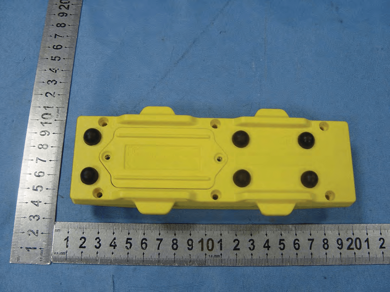
M745629
May 10, 2012Beach Bulter xp
Equipment Class
DSC - Part 15 Security/Remote Control Transmitter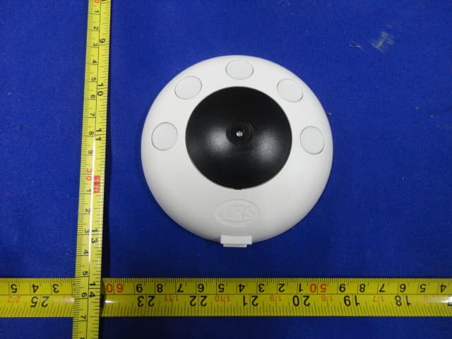
M74PRONTO
Feb 12, 2012PRONTO
Equipment Class
DSC - Part 15 Security/Remote Control Transmitter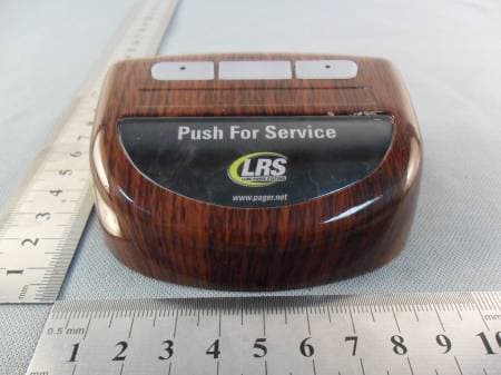
M74TGUHF
Jul 20, 2011Table Genie UHF
Equipment Class
DSC - Part 15 Security/Remote Control Transmitter
M74T7400
Mar 23, 2000On Site Pager
Equipment Class
TNB - Licensed Non-Broadcast Station Transmitter