M9H-MA220MA220
Sagem Wireless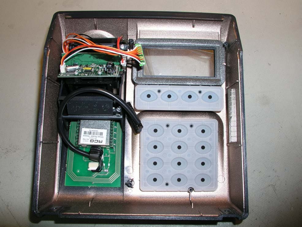
Click to zoom
Application Details
- Equipment Class
- DXT - Part 15 Low Power Transceiver, Rx Verified
- Date of Grant
- Sep 28, 2003
- Application Purpose
- Original Equipment
- Date of Application
- Sep 28, 2003
- Equipment Note
- MA220
- Frequency Range
- 13.56000000 - 13.56000000
- Company
- Sagem Wireless
- Country
- France
Documents & Files
Document Text
Text extracted from the exhibit documents filed with the FCC. Open a document above to read the original.
Users Manual
1 23 23 MorphoAccess TM 200/300 Installation Guide SAGEM MORPHO, Inc. 1145 Broadway Plaza, Suite 200 Tacoma, WA. 98402 i CONTENTS Welcome to MorphoAccess™ 1 Safety instructions 2 General description 4 Installation procedure 5 Stage 1: Drilling the mounting holes for the metal chassis assembly 5 Stage 2: Mounting the metal chassis assembly 6 Stage 3: Connecting the chassis assembly to the cover assembly 7 Stage 4: Closing MorphoAccess™ 8 How to upgrade MorphoAccess™ 200 to 300 9 Electrical interfaces 10 Terminal block board 10 Power supply cable 11 COM1 RS485/422 serial port wiring 11 COM1 Deister wiring (optional) 12 Ethernet wiring 12 COM2 RS232 wiring 13 COM2 RS422 wiring 14 Wiegand output wiring 14 Wiegand input wiring 15 Data clock output wiring 15 Data clock input wiring 16 Input / output wiring (optional) 17 Output relays and Tamper switch 18 Configuring the MorphoAccess TM 19 Motherboard configuration 19 Optional communications cable 20 MorphoAccess™ Technical characteristics 21 Display 21 Keyboard 21 Fuse 21 Memory 21 Peripherals interfaces 21 Contents ii1 Power supply 22 Size and weight 22 Environmental conditions 22 Storage conditions 22 Recommendations 23 Areas containing combustibles 23 General precautions 23 Appendix 1 - Ethernet color standard 24 Appendix 2 - Wiegand data format 25 Appendix 3 - ISO 7811/2-1995 - Track 2 Dataclock format 26 Appendix 4 - Reserved configuration keys 28 Appendix 5 - Morpho Product Warranty and End-User Software License 29 Drilling Template 32 Contents ii1 Welcome to MorphoAccess™ Congratulations for choosing the MorphoAccess™ Automatic Fingerprint Recognition Terminal. MorphoAccess™ provides an innovative and effective solution for access control or time and attendance applications using fingerprint verification and/or identification. Among a range of alternative biometric techniques, the use of finger imaging has significant advantages: each finger constitutes an unalterable physical signature which develops before birth and is preserved until death. Unlike DNA, a finger image is unique to each individual - even identical twins. The MorphoAccess™ terminal integrates SAGEM image processing and feature matching-algorithms (MorphoSoft™ and MorphoImaging™). This technology is based on lessons learned during 18 years of experience in the field of biometric identification and the creation of literally millions of individual fingerprint identification records. We believe that you will find the MorphoAccess™ fast, accurate, easy to use and suitable for physical access control or time and attendance. The MorphoAccess™ offers the following features: - High quality optical scanner - Supports multiple input/output interfaces used in the physical access control industry - Local area network interface for easy interaction with other host systems - Compact size for easy installation and integration into your available office space - Intuitive interface that is easy to use in both setup and operational modes - Extensive, flexible flash memory for data storage (user data, biometric templates, etc.) To ensure the most effective use of your MorphoAccess™, please read this Installation Guide in full. The SAGEM logo and trademark are the property of E. All other trademarks or product names are trademarks or product names of the respective title holders. Introduction 23 Safety instructions – Please Read Before Installation WARNING: Installation must be performed by professional installers Note: These instructions for the installation of the MorphoAccess assume the installer is properly qualified as a professional, and is familiar with applicable industry standards, local building/zoning codes, and proper installation practices. Installation should not be attempted by non-professionals. You are required to use an NEC class II power supply at 12 V ± 5% and 2.5 A minimum. This product is intended to be installed in accordance with the NEC Class 2 requirements; or supplied by a listed external Power Unit marked Class 2, Limited Power source, or LPS and rated 12 V DC, 2.5 A minimum. Europe: SAGEM SA hereby declares that the SAGEM SA MorphoAccess™ has been tested and found compliant with the below listed standards as required by the EMC Directive 89/336/ EEC: EN55022 (1994) / EN55024 (1998) and by the low voltage Directive 73/23/EEC amended by 93/68/EEC: EN60950 (2000). USA: This equipment has been tested and found compliant with Class B digital device requirements, pursuant to part 15 of the FCC Rules. These requirements are designed to ensure reasonable protection against harmful RF interference in a residential installation. This equipment generates, uses and can radiate radio frequency energy and, if not installed and used in accordance with the instructions, may interfere with radio communications. If this equipment interferes with radio or television reception - which can be determined by disconnecting and re-connecting the unit - the user is encouraged to try to correct the interference by one or more of the following measures: - Reorient or relocate the receiving antenna - Increase the separation between the equipment and receiver - Connect the equipment into an outlet on a circuit different from that to which the receiver is connected - Consult the dealer or an experienced radio/TV technician for help Safety instructions 23 CAUTION DANGER OF EXPLOSION IF BATTERY IS INCORRECTLY REPLACED. REPLACE ONLY WITH THE SAME OR EQUIVALENT TYPE RECOMMENDED BY THE MANUFACTURER. MUST BE DISPOSED OF PROPERLY. ATTENTION IL Y A DANGER D’EXPLOSION S’IL Y A REMPLACEMENT INCORRECT DE LA BATTERIE. REMPLACER UNIQUEMENT AVEC UNE BATTERIE DU MEME TYPE OU D’UN TYPE EQUIVALENT RECOMMANDE PAR LE CONSTRUCTEUR. ELIMINER DE FAÇON APPROPRIÉE Safety instructions 45 General description General description 45 Installation procedure Stage 1: Drilling the mounting holes for the metal chassis assembly Mounting and cable entry hole location (rear view) Note: The mounting screws can not exceed 5 mm in…
Text truncated - open the document above for the full version.
Cover Letter(s)
Northwest EMC TCB Compliance Opinion Rev. 9/15/03 SAGM0001 Information about the Applicant Company Name Sagem Morpho, Inc. Address 1145 Broadway Plaza, Suite 200 City, State, Zip Tacoma, WA 98402 Requested By Eric L. Vogel Job Number SAGM0001 Model MA220 FCC ID M9H-MA220 Agent Northwest EMC, Inc. Approval Type Original Equipment Class DXT Part 15, Low Power Transceiver, Rx Verified Rule Part 15.225 Overview The radio is an ISO/IEC 14443 type Mifare remote RFID card reader. It is a seeking certification under FCC 15.225. The device uses a single antenna, integral to the circuit board. Recommendation All items have been resolved and completed to my satisfaction; therefore I recommend this application for approval. 9/26/03 _______________________________ ________________ Name, Title Date Northwest EMC TCB Compliance Opinion Rev. 9/15/03 SAGM0001 Findings and Resolution Item 15.19 The required labeling was not located on the device nor in the user manual. Resolution Requirements and Opinion Specification Requirements Description 47 CFR 2.1033(b)(3) Installation, operating instructions, user information Opinion The device complies with the requirements. Discussion The client has submitted the required information. Reference User Manual.pdf, Specification Requirements Description 47 CFR 2.1033(b)(4) Operational description Opinion The device complies with the requirements. Discussion The client has submitted the required information. Reference Operational description.pdf Specification Requirements Description 47 CFR 2.1033(b)(5) Block diagram showing frequency of oscillators. Signal path and frequency at each block. Opinion The device complies with the requirements. Discussion The client has submitted the required information. Reference Block Diagram.pdf Specification Requirements Description 47 CFR 2.1033(b)(5) Schematic diagram Opinion The device complies with the requirements. Discussion The client has submitted the required information. Reference Schematics.pdf, Northwest EMC TCB Compliance Opinion Rev. 9/15/03 SAGM0001 Specification Requirements Description 47 CFR 2.1033(b)(7) Internal and external photos Opinion The device complies with the requirements. Discussion The client has submitted the required information. Reference User Manual.pdf, Schematics.pdf, Operational description.pdf Specification Requirements Description 47 CFR 15.19 Label requirements Opinion The device complies with the requirements. Discussion The client has submitted the required information. Reference User Manual.pdf Specification Requirements Description 47 CFR 15.21 User Information Opinion The device complies with the requirements. Discussion The client has submitted the required information. Reference User Manual.pdf Specification Requirements Description 47 CFR 15.27 Special Accessories (Shielded cables, etc.) Opinion The device complies with the requirements Discussion The manufacturer supplies required ferrite beads.. Reference User Manual.pdf. Specification Requirements Description 47 CFR 15.33 Frequency range Opinion The data complies with the requirements. Discussion The client has submitted a test report. Reference Technical Report-PLEX0339.pdf Specification Requirements Description 47 CFR 15.35 Measurement Detectors Opinion The data complies with the requirements. Discussion The client has submitted a test report. Reference Technical Report-PLEX0339.pdf Northwest EMC TCB Compliance Opinion Rev. 9/15/03 SAGM0001 Specification Requirements Description 47 CFR 15.205 Restricted band(s) requirements Opinion The data complies with the requirements. Discussion The client has submitted a test report. Reference Technical Report-PLEX0339.pdf Specification Requirements Description 47 CFR 15.207 Powerline Conducted Emissions Opinion The device complies with the requirements. Discussion The client has submitted a test report. Reference Technical Report-PLEX0339.pdf Specification Requirements Description 47 CFR 15.209 Spurious Emissions Opinion The device complies with the requirements. Discussion The client has submitted a test report. Reference Technical Report-PLEX0339.pdf Specification Requirements Description 47 CFR 15.225(a) Field Strength of Fundamental Opinion The device complies with the requirements. Discussion The client has submitted a test report. Reference Technical Report-PLEX0339.pdf Specification Requirements Description 47 CFR 15.225(b) Field Strength of Spurious Emissions Opinion The device complies with the requirements. Discussion The client has submitted a test report. Reference Technical Report-PLEX0339.pdf Specification Requirements Description 47 CFR 15.225(c) Frequency Stability Opinion The device complies with the requirements. Discussion The client has submitted a test report. Reference Technical Report-PLEX0339.pdf
Cover Letter(s)
NORTHWEST EMC, INC. 22975 NW Evergreen Parkway, Suite 400 Hillsboro, OR 97124 September 24, 2003 Dear Application Examiner: On behalf of SAGEM Morpho, Inc., Northwest EMC Inc is submitting this application for the certification of SAGEM Morpho’s MA220 indoor biometric access control terminal, FCC ID: M9H-MA220. The radio is an ISO/IEC 14443 type Mifare contactless RFID card reader. It is a seeking certification under FCC 15.225. The EUT utilizes a single antenna integral to the unit. The technical reports and exhibits demonstrate compliance with FCC rules 47 CFR 15.225. Your efforts in reviewing this application are greatly appreciated. Best regards, Greg Kiemel, Director of Engineering Northwest EMC, Inc.
Cover Letter(s)
August 25, 2003 Federal Communications Commission Authorization and Evaluation Division 7435 Oakland Mills Road Columbia, MD 21046 To whom it may concern, We, the undersigned, hereby authorize Northwest EMC, Inc., to act on our behalf, as our agent, in the following matters related to the FCC approval of our products: report submittal, related correspondence, the signing of all documents relating to these matters, and any other lawful activity necessary to obtain such certification. Any act carried out by Northwest EMC, Inc. within the scope of this authorization shall have the same effect as our own. This authorization shall expire 12 months from original date. Sincerely, Michael C. Anderson Corporate Counsel SAGEM Morpho, Inc. 1145 Broadway Plaza, Suite 200 Tacoma, WA 98402 Phone: (253) 597-8243 Fax: (253) 591-8856 Email: [email protected]
Cover Letter(s)
September 2, 2003 Federal Communications Commission Authorization and Evaluation Division 7435 Oakland Mills Road Columbia, MD 21046 To whom it may concern, We hereby respectfully request that under the provision of 47 CFR 0.459, the documents listed below and attached with this application for certification be provided with confidential status. • Schematics • Operational Description • Block Diagram Any exhibit / information for which we have requested confidentiality, but which may not be accorded such treatment by the FCC, should be returned to us. The documents listed above contain trade secrets that are treated as confidential by us and our suppliers. Substantial competitive harm to us or our suppliers could result should they be made available to the public. Sincerely, Michael C. Anderson Corporate Counsel SAGEM Morpho, Inc. 1145 Broadway Plaza, Suite 200 Tacoma, WA 98402 Phone: (253) 597-8243 Fax: (253) 591-8856 Email: [email protected]
Test Report
Plexus MA 220 May 16, 2003 Report No. PLEX0339 Report Prepared By: 1-888-EMI-CERT © 2003 Northwest EMC, Inc 22975 NW Evergreen Parkway Suite 400 Hillsboro, Oregon 97124 Certificate of Test Issue Date: May 16, 2003 Plexus Model : MA 220 Emissions Description Pass Fail FCC 15.207, AC Powerline Conducted Emissions FCC 15.225, Field Strength of Fundamental FCC 15.225, Field Strength of Spurious Emissions FCC 15.225, Frequency Stability The equipment was tested in the configuration and mode(s) of operation provided by the client. The specific tests and test levels were specified by the client. Any additional tests, or product configurations that should be tested are the responsibility of the client. Product compliance is the responsibility of the client. Modifications made to the product • See the modifications page of the report Deviations to the test standard • No deviations were made to the test standard Approved By: Dean Ghizzone, President This Report may only be duplicated in its entirety. The results of this test pertain only to the sample(s) tested, the specific description is noted in each of the individual sections of the test report supporting this certificate of test. Northwest EMC Revision History Revision 05/05/03 Revision Number Description Date Page Number 00 None Northwest EMC Accreditations and Authorizations Revision 03/05/03 FCC: The Open Area Test Sites, and conducted measurement facilities, have been fully described in reports filed with the FCC and accepted by the FCC in letters maintained in our files. TCB: Northwest EMC has been accredited by ANSI to ISO/IEC Guide 65 as a product certifier. We have been designated by the FCC as a Telecommunications Certification Body (TCB). This allows Northwest EMC to certify transmitters to FCC specifications in accordance with 47 CFR 2.960 and 2.962. A2LA: Accreditation has been granted to Northwest EMC, Inc. to perform the Electromagnetic Compatibility (EMC) tests described in the Scope of Accreditation. Assessment performed to ISO/IEC 17025. Certificate Number: 1936-01, Certificate Number: 1936-02, Certificate Number 1936-03 Australia/New Zealand: The National Association of Testing Authorities (NATA), Australia has been appointed by the ACA as an accreditation body to accredit test laboratories and competent bodies for EMC standards. Accredited test reports or assessments by competent bodies must carry the NATA logo. Test reports made by an overseas laboratory that has been accredited for the relevant standards by an overseas accreditation body that has a Mutual Recognition Agreement (MRA) with NATA are also accepted as technical grounds for product conformity. The report should be endorsed with the respective logo of the accreditation body. (A2LA) TÜV Product Service: Included in TUV Product Service Group's Listing of Recognized Laboratories. It qualifies in connection with the TUV Certification after Recognition of Agent's Testing Program for the product categories and/or standards shown in TUV's current Listing of CARAT Laboratories available from TUV. A certificate was issued to represent that this laboratory continues to meet TUV's CARAT Program requirements. Certificate No. USA0302C TÜV Rheinland: Authorized to carryout EMC tests by order and under supervision of TÜV Rheinland. This authorization is based on "Conditions for EMC-Subcontractors" of November 1992. Northwest EMC Accreditations and Authorizations Revision 03/05/03 NEMKO: Assessed and accredited by NEMKO (Norwegian testing and certification body) for European emissions and immunity testing. As a result of NEMKO's laboratory assessment, they will accept test results from Northwest EMC, Inc. for product certification (Authorization No. ELA 119). Technology International: Assessed in accordance with ISO Guide 25 defining the general international requirements for the competence of calibration and testing laboratories and with ITI assessment criteria LACO196. Based upon that assessment Interference Technology International, Ltd., has granted approval for specifications implementing the EU Directive on EMC (89/336/EEC and amendments). The scope of the approval was provided on a Schedule of Assessment supplied with the certificate and is available upon request. Industry Canada: Accredited by Industry Canada for performance of radiated measurements. Our open area test sites comply with RSP 100, Issue 7, section 3.3. VCCI: Accepted as an Associate Member to the VCCI, Acceptance No. 564. Conducted and radiated measurement facilities have been registered in accordance with Regulations for Voluntary Control Measures, Article 8. (Registration Nos. - Evergreen: C-1071 and R-1025, Trails End: C-694 and R-677, Sultan: C-905, R-871 and R-1172, North Sioux City C-1246, R-1185 and R-1217) BSMI: Northwest EMC has been designated by NIST and validated by C- Taipei (BSMI) as a CAB to conduct tests as described in the APEC Mutual Recognition Agreement. License No.SL2-IN-E-1017. CAB: Designated by NIST and validated by the European Commission as a Conformity Assessment Body (CAB) to conduct tests and approve products to the EMC directive and transmitters to the R&TTE directive, as described in the U.S. - EU Mutual Recognition Agreement GOST: Northwest EMC, Inc. has been assessed and accredited by the Russian Certification bodies Certinform VNIINMASH, CERTINFO, SAMTES, and Federal CHEC, to perform EMC and Hygienic testing for Information Technology Products. As a result of their laboratory assessment, they will accept test results from Northwest EMC, Inc. for product certification Northwest EMC Scope of Accreditations Revision 03/05/03 FCC NIST TUV PS TUV Rheinland Nemko Technology International Industry Canada BSMI VCCI GOST NATA IEC 1000-4-2 IEC 1000-4-3 IEC 1000-4-4 IEC 1000-4-5 IEC 1000-4-6 IEC 1000-4-8 IEC 1000-4-11 IEC 1000-3-2 IEC 1000-3-3 AS/NZS 3548 CNS 13438 ISO/IEC Guide 25 ISO/IEC17025 Radiated Emissions Conducted Emissions OATS Sites Hillsboro 5-Meter Chamber (EV01) TCB fo…
Text truncated - open the document above for the full version.
Test Report
Type of equipment tested: Pre-production Modifications made during testing that are required for FCC compliance and will be incoporated into all production units: A single one-turn ferrite was added to all the external I/O cables together. (see attached excerpt from User Manual) Description of the software and firmware used to operate the radio, including name and revision level: MorphoAccess firmware version 4.42, consisting of the following files: dbiorom_4.42.edb static_kernel_4.42.edb spilv_4.42.edb maccess_4.42.edb langue0.bin langue1.bin langue2.bin ACG H102014BC firmware version 0.14e Installing Ferrite Beads on Interface Cables for MorphoAccess™ 220 and 320 This document provides an overview of ferrite beads and explains how to install them on the power, Wiegand, RS-422, and Ethernet cables that you connect to the MorphoAccess™ 220 or 320. To meet FCC requirements for Class B computing devices, a ferrite bead must be installed on all cables connected to the MorphoAccess. What is a Ferrite Bead? Ferrite beads are radio frequency (RF) absorbers. To see an example of a ferrite bead, look at a monitor video cable or a laptop computer power cable that is connected to your computer. The walnut-sized protrusion that is molded near one end of the cable is a ferrite bead. The size and shape of the ferrite bead determines the amount of RF that is absorbed. The amount of RF that a device emits determines the type of ferrite bead that is required to provide the proper absorption. The ferrite beads supplied with your MorphoAccess 220 or 320 terminal have been properly sized to absorb the correct amount of RF to comply with FCC requirements. Installing a Ferrite Bead After all the cables have been routed through the wall, place a single ferrite bead around all of them before you install the MorphoAccess 220 or 320 terminal. See instructions below. The foam strip will be compressed in the ferrite bead to prevent the ferrite bead from slipping down the cable. 1. Open a ferrite bead by releasing the clasp on the side. 2. Determine where the ferrite bead will be positioned on the cables. It should be positioned as close as possible (but not inside) to the MorphoAccess terminal. Ensure that sufficient cable slack will be available to route the cables inside the MorphoAccess and to attach the wires to the terminal block. AUGUST 2003 SAGEM MORPHO, Inc. 2003. All rights reserved. 5 3. Wrap the foam tightly around all the cables at the position where the ferrite bead will be placed. 4. Lay the foam-wrapped cable inside the groove of the ferrite bead. 5. Close the two halves of the ferrite bead and securely fasten the clasps. If the ferrite bead does not close easily, trim the foam slightly, but not so much that the ferrite bead will slide away from the terminal. Ordering Ferrite Beads or Foam Cable Wrap for Ferrites To order more ferrite beads (Fair-Rite 04441 73551) for your MorphoAccess 220 or 320 interface cables, contact SAGEM MORPHO, Inc. at 1-800-526-2674. Ask for part number 1205- 364001-0. To order more foam cable wrap for ferrites, ask for part number 0999-900019-0. 6 SAGEM MORPHO, Inc. 2003. All rights reserved. AUGUST 2003
Test Report
The antenna design consists of a permanently attached, integral, non-interchangeable radiating element and is therefore compliant with paragraph 15.203 of the FCC rules. The device operates at 13.56 MHz ± 7 kHz and this is not a Part 15.247 transmitter. The unit operates only with the integral PCB loop-type antenna (internal SAGEM part number 3000015331).
Contact Information
Applicant
Francois CHAMBON(GM)
Technical Contact
Northwest EMC, Inc.Greg Kiemel
[email protected]503-844-4066
22975 NW Evergreen Parkway · Hillsboro, Oregon · United States
Non-Technical Contact
Northwest EMC, Inc.Vicki Albertson
[email protected]503-844-4066
Test Firm
Northwest EMC, Inc.Greg Kiemel
Technical Specifications
| # | Rule Parts | Frequency Range | Power Output |
|---|---|---|---|
| 1 | 15C | 13.56 MHz - 13.56 MHz | - |
Other Applications from Sagem Wireless
M9HCOSY3G
Oct 13, 2010COSY Phone 3G
Equipment Class
DXX - Part 15 Low Power Communication Device Transmitter
M9HCOSY2G
Sep 06, 2010COSY Phone 2G
Equipment Class
PCE - PCS Licensed Transmitter held to ear
M9HMOV001
Aug 18, 2010Handheld Top Up Terminal
Equipment Class
PCT - PCS Licensed Transmitter worn on body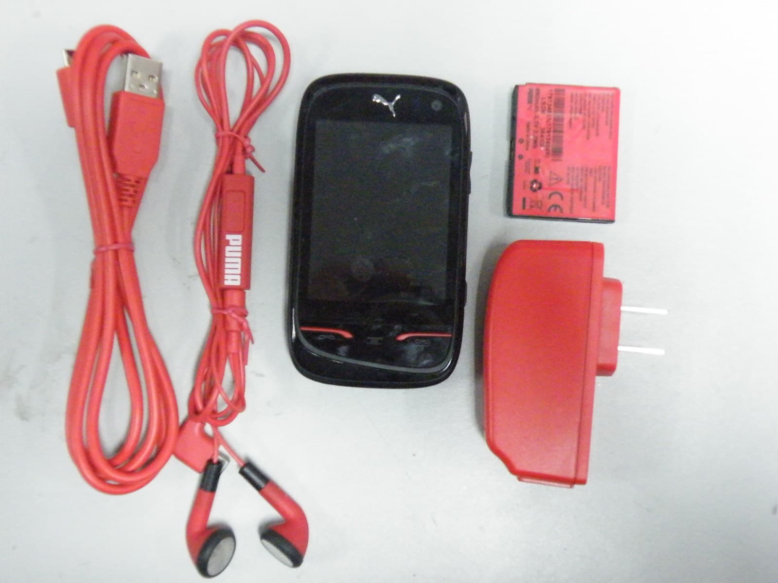
M9HPM1
Apr 26, 2010Mobile phone
Equipment Class
PCE - PCS Licensed Transmitter held to ear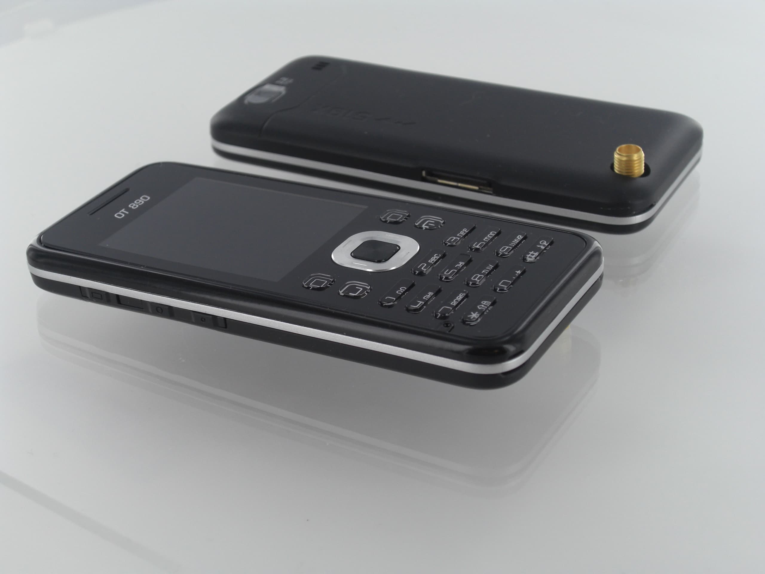
M9HOT8X0RF
Jan 31, 2010Network Measurement Device
Equipment Class
JBP - Part 15 Class B Computing Device Peripheral