M9H95EP05CGSM 900/1800/1900 Mobile Phone
Sagem Wireless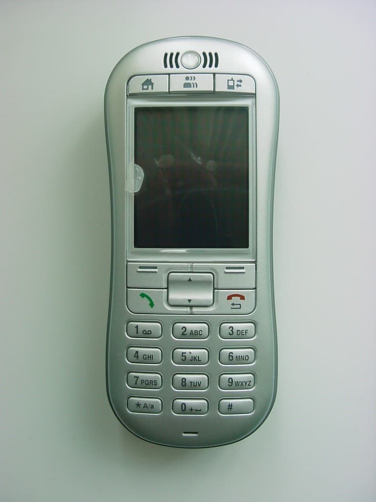
Click to zoom
Application Details
- Equipment Class
- PCE - PCS Licensed Transmitter held to ear
- Date of Grant
- Apr 21, 2005
- Application Purpose
- Original Equipment
- Date of Application
- Apr 21, 2005
- Equipment Note
- GSM 900/1800/1900 Mobile Phone
- Frequency Range
- 1850.20000000 - 1909.80000000
- Company
- Sagem Wireless
- Country
- France
Documents & Files
Document Text
Text extracted from the exhibit documents filed with the FCC. Open a document above to read the original.
Users Manual
The book for your Vodafone Simplymobile phone Vodafone Simply Sagem VS1 A reassuringly brief guide to using your new mobile phone user_man_cover_VS1_UK 18/4/05 12:34 pm Page 1 The phone with common sense as a feature Vodafone Simply user_man_cover_VS1_UK 18/4/05 12:34 pm Page 2 2.How to insert the SIM card 4.How to charge the battery 6.So what do all these buttons do? 8.How to use the buttons on the phone 10.What does everything on my Home screen mean? 12.How do I add people to my Phone Book? 14.How to make and receive calls 16.How to send a text message 17.How to receive a text message 18.How do I set reminders? 19.How do I ask for help? 20.How do I adjust the clock and other settings? 21.What is my Phone Book Manager? 22.How do I use my Phone Book Manager? 24.How do I create new contacts and transfer them to my phone? 25.How are my contacts saved? 26.The importance of regularly ‘Backing Up’ 27.How do I restore my contacts? 28.How do I close my Phone Book Manager safely 29.What’s in the box 30.A closer look at the detail Contents user_manual_Silver_UK 18/4/05 12:26 pm Page 1 You wanted a mobile phone that’s sophisticated yet easy to use and here it is in your hands! Naturally you’re eager to start using it, but first you need to insert the SIM card. Page 2 How to insert the SIM card The SIM card lives under the battery. Here’s how to insert it: •Ensure that the phone is switched off and the charger is disconnected from the bottom of the phone. •Turn the phone over and push the lock button upwards. •Remove the back cover by lifting the bottom end first. •If the battery is already inside remove it. •Hold your SIM card with the cut corner oriented as shown and then slide it into the card holder face down. •Replace the battery first. •Replace the back cover clicking in the top edge then the lower end and push the catch downwards into the locked position. user_manual_Silver_UK 18/4/05 12:26 pm Page 2 Page 3 Lock What is a SIM card? Every mobile phone has a SIM card. (Subscriber Identity Module). This is a microchip that holds your personal information such as your phone number, and the names and numbers of your friends and family. Your phone won’t work without it. If you already have contacts on your SIM card these can be transferred across in most cases. user_manual_Silver_UK 18/4/05 12:27 pm Page 3 Your phone is powered by a rechargeable battery. This needs to be chargedfor at least 4 hoursbefore you can make your first call. Ready? Charge! Page 4 Charging the battery •Plug the charger into the mains and the phone. •The phone is now charging. The battery icon moves from left to right. •When the icon stops moving and the percentage of charge shows 100% the battery is fully charged. •Disconnect the charger. How to charge the battery user_manual_Silver_UK 18/4/05 12:27 pm Page 4 Page 5 When you are at home, just sit the phone in the charging cradle and plug it into the mains. That way your phone will always be charged when you need it and you will always be able to find it. You can always check the battery icon to see how much power you have left. When it’s red you know it’s time to recharge. You will also see a message on the screen when you need to recharge it. Recharge for at least 15 minutes before making another call so your phone doesn’t cut out in the middle of a call! (Your battery has a standby time of up to 12 days or you can make calls of up to 4 hours before recharging again). Charging cradle user_manual_Silver_UK 18/4/05 12:27 pm Page 5 • On/off –Turns the phone on and off, just press and hold down the button on the top. • Home –Returns you to the ‘Home Screen’, the original screen that you see when you switch on the phone. • Contacts –Opens your phone book where you keep your family and friends’ details. • Log –Where you can find all your messages in one place. Just press this button and you can access your voice and text messages, missed calls, and reminders. Page 6 At the top of the phone you’ll see three special buttons, each of which has a dedicated function. Basically this means less searching through menus. So what do all these buttons do? user_manual_Silver_UK 18/4/05 12:27 pm Page 6 Home On/off Contacts Log Page 7 user_manual_Silver_UK 18/4/05 12:27 pm Page 7 On the side of the phone you’ll see three more buttons: • Ringer Setting (right side) –Easily set the ringer to loud,normal, vibrate or silent. • Volume Key (left side) –While you are in a call you can use this button to adjust the volume. • Button Lock (right side) –Lock the keypad to avoid making accidental calls! Below the screen you’ll find the main function keys: • Hello –Answer incoming calls with this key. • Goodbye –Hang up with this key. When not in a call button may be pressed to return to previous screen. • Up/Down –To navigate through menus and phone book entries. • Menu Keys –Press these buttons to select the command written above them on the screen. Page 8 How to use the buttons on the phone user_manual_Silver_UK 18/4/05 12:27 pm Page 8 Volume Up/down Menu key Hello Goodbye Button lock Menu key Ringer setting Page 9 user_manual_Silver_UK 18/4/05 12:27 pm Page 9 On the ‘Home’ screenyou will see the following settings: Clock –Displays the time. Ringer Setting –Loud,normal, vibrate or silent as set by the button on the side of the phone. Battery Indicator –Shows the amount of power left. Network Signal –Shows the strength of your connection to the mobile phone network. Your Number –Handy when someone asks you for your phone number and you go, “It’s... oh, wait a minute, what is it again?” Page 10 What does everything on my Home screen mean? user_manual_Silver_UK 18/4/05 12:27 pm Page 10 Page 11 Home user_manual_Silver_UK 18/4/05 12:27 pm Page 11 •Press the ‘Contacts’button (the one with people on it). •Select‘ADD NEW CONTACT’. •Enter a name using the number keys and confirm by clicking ‘OK’. •Enter the contacts’ phone number. •Choose‘SAVE’. You can also save a number right after you’ve made or received a …
Text truncated - open the document above for the full version.
External Photos
CETECOM ICT Services GmbH Untertürkheimer Str. 6-10, 66117 Saarbruecken Phone: +49 (0) 681 598-0 Fax: -9075 RSC-Laboratory Phone: +49 (0) 681 598-0 Fax: -9075 Annex to Test report no.: 4-1607-06-05/05 Date: 2005-04-05 Page 54 of 70 6 Annex C: External Photographs of the Equipment Photo 1: CETECOM ICT Services GmbH Untertürkheimer Str. 6-10, 66117 Saarbruecken Phone: +49 (0) 681 598-0 Fax: -9075 RSC-Laboratory Phone: +49 (0) 681 598-0 Fax: -9075 Annex to Test report no.: 4-1607-06-05/05 Date: 2005-04-05 Page 55 of 70 Photo 2:
ID Label/Location Info
Sagem SA TELEPHONIE MOBILE MOBILE PHONES Date : 24/01/05 Centre de Saint Christophe - DTM Curvy Document SAGEM SA Reproduction et divulgation interdites 19/28 Sagem SA TELEPHONIE MOBILE MOBILE PHONES Date : 24/01/05 Centre de Saint Christophe - DTM Label location 2.2 THE BATTERIES See file Battery repertory 3. Document SAGEM SA Reproduction et divulgation interdites 20/28
Internal Photos
CETECOM ICT Services GmbH Untertürkheimer Str. 6-10, 66117 Saarbruecken Phone: +49 (0) 681 598-0 Fax: -9075 RSC-Laboratory Phone: +49 (0) 681 598-0 Fax: -9075 Annex to Test report no.: 4-1607-06-05/05 Date: 2005-04-05 Page 56 of 70 Photo 3: CETECOM ICT Services GmbH Untertürkheimer Str. 6-10, 66117 Saarbruecken Phone: +49 (0) 681 598-0 Fax: -9075 RSC-Laboratory Phone: +49 (0) 681 598-0 Fax: -9075 Annex to Test report no.: 4-1607-06-05/05 Date: 2005-04-05 Page 57 of 70 7 Annex D: Internal Photographs of the Equipment Photo 1: CETECOM ICT Services GmbH Untertürkheimer Str. 6-10, 66117 Saarbruecken Phone: +49 (0) 681 598-0 Fax: -9075 RSC-Laboratory Phone: +49 (0) 681 598-0 Fax: -9075 Annex to Test report no.: 4-1607-06-05/05 Date: 2005-04-05 Page 58 of 70 Photo 2: CETECOM ICT Services GmbH Untertürkheimer Str. 6-10, 66117 Saarbruecken Phone: +49 (0) 681 598-0 Fax: -9075 RSC-Laboratory Phone: +49 (0) 681 598-0 Fax: -9075 Annex to Test report no.: 4-1607-06-05/05 Date: 2005-04-05 Page 59 of 70 Photo 3: CETECOM ICT Services GmbH Untertürkheimer Str. 6-10, 66117 Saarbruecken Phone: +49 (0) 681 598-0 Fax: -9075 RSC-Laboratory Phone: +49 (0) 681 598-0 Fax: -9075 Annex to Test report no.: 4-1607-06-05/05 Date: 2005-04-05 Page 60 of 70 Photo 4: CETECOM ICT Services GmbH Untertürkheimer Str. 6-10, 66117 Saarbruecken Phone: +49 (0) 681 598-0 Fax: -9075 RSC-Laboratory Phone: +49 (0) 681 598-0 Fax: -9075 Annex to Test report no.: 4-1607-06-05/05 Date: 2005-04-05 Page 61 of 70 Photo 5:
Parts List/Tune Up Info
Tune-up procedure for EP2005 During manufacturing each phone will be individually calibrated. The measurement is done in a fully calibrated setup, which is based on a Wavetek 4400 base station simulator (system tester). Furthermore, the highest power level is verified afterwards in a call measurement on three channels (low, mid and high) in each Band (GSM900 and DCS1800 and PCS 1900) Procedure : 1. Set the phone to operational voltage (3.9V) and on one certain channel (TCH 37 for GSM 900 Band, TCH 702 for DCS1800 Band and TCH 661 for PCS1900 Band) in Burn- In Mode (Test Software, the phone is in emission mode only). 2. The actual power is measured at 2 different power levels. 3. Gain factor is adjusted for PL min 4. Thanks to Step 2 and 3, the gain factors of each individual phone are calculated and stored in each phone individually. 5. All power level are measured for checking. The user has no possibility to change these settings later on.
RF Exposure Info
CETECOM ICT Services GmbH Untertuerkheimer Str. 6-10, 66117 Saarbruecken, Germany Phone: +49 (0) 681 598-0 Fax: -8475 SAR-Laboratory Phone: +49 (0) 681 598-8454 . As of 2005-04-15 Page 1 of 28 Accredited testing laboratory DAR registration number: TTI-P-G 166/98 Federal Motor Transport Authority (KBA) DAR registration number: KBA-P 00070-97 Appendix to test report 4-1607-06-03/05-C Calibration data, Phantom certificate and detail information of the DASY4 System CETECOM ICT Services GmbH Calibration Data and Phantom Information to test report no.: 4-1607-06-03/05-C As of 2005-04-15 Page 2 of 28 Table of Content 1 Calibration report “Probe ET3DV6” .................................................................................................................................... 3 2 Calibration report “1900 MHz System validation dipole .................................................................................................. 11 3 Calibration certificate of Data Aquisition Unit (DAE) ...................................................................................................... 20 4 Certificate of “SAM Twin Phantom V4.0/V4.0C” ........................................................................................................... 21 5 Application Note System Performance Check ................................................................................................................... 23 2005-04-15 CETECOM ICT Services GmbH Calibration Data and Phantom Information to test report no.: 4-1607-06-03/05-C As of 2005-04-15 Page 3 of 28 1 Calibration report “Probe ET3DV6” CETECOM ICT Services GmbH Calibration Data and Phantom Information to test report no.: 4-1607-06-03/05-C As of 2005-04-15 Page 4 of 28 CETECOM ICT Services GmbH Calibration Data and Phantom Information to test report no.: 4-1607-06-03/05-C As of 2005-04-15 Page 5 of 28 CETECOM ICT Services GmbH Calibration Data and Phantom Information to test report no.: 4-1607-06-03/05-C As of 2005-04-15 Page 6 of 28 CETECOM ICT Services GmbH Calibration Data and Phantom Information to test report no.: 4-1607-06-03/05-C As of 2005-04-15 Page 7 of 28 CETECOM ICT Services GmbH Calibration Data and Phantom Information to test report no.: 4-1607-06-03/05-C As of 2005-04-15 Page 8 of 28 CETECOM ICT Services GmbH Calibration Data and Phantom Information to test report no.: 4-1607-06-03/05-C As of 2005-04-15 Page 9 of 28 CETECOM ICT Services GmbH Calibration Data and Phantom Information to test report no.: 4-1607-06-03/05-C As of 2005-04-15 Page 10 of 28 CETECOM ICT Services GmbH Calibration Data and Phantom Information to test report no.: 4-1607-06-03/05-C As of 2005-04-15 Page 11 of 28 2 Calibration report “1900 MHz System validation dipole CETECOM ICT Services GmbH Calibration Data and Phantom Information to test report no.: 4-1607-06-03/05-C As of 2005-04-15 Page 12 of 28 CETECOM ICT Services GmbH Calibration Data and Phantom Information to test report no.: 4-1607-06-03/05-C As of 2005-04-15 Page 13 of 28 CETECOM ICT Services GmbH Calibration Data and Phantom Information to test report no.: 4-1607-06-03/05-C As of 2005-04-15 Page 14 of 28 CETECOM ICT Services GmbH Calibration Data and Phantom Information to test report no.: 4-1607-06-03/05-C As of 2005-04-15 Page 15 of 28 CETECOM ICT Services GmbH Calibration Data and Phantom Information to test report no.: 4-1607-06-03/05-C As of 2005-04-15 Page 16 of 28 CETECOM ICT Services GmbH Calibration Data and Phantom Information to test report no.: 4-1607-06-03/05-C As of 2005-04-15 Page 17 of 28 CETECOM ICT Services GmbH Calibration Data and Phantom Information to test report no.: 4-1607-06-03/05-C As of 2005-04-15 Page 18 of 28 CETECOM ICT Services GmbH Calibration Data and Phantom Information to test report no.: 4-1607-06-03/05-C As of 2005-04-15 Page 19 of 28 CETECOM ICT Services GmbH Calibration Data and Phantom Information to test report no.: 4-1607-06-03/05-C As of 2005-04-15 Page 20 of 28 3 Calibration certificate of Data Aquisition Unit (DAE) CETECOM ICT Services GmbH Calibration Data and Phantom Information to test report no.: 4-1607-06-03/05-C As of 2005-04-15 Page 21 of 28 4 Certificate of “SAM Twin Phantom V4.0/V4.0C” CETECOM ICT Services GmbH Calibration Data and Phantom Information to test report no.: 4-1607-06-03/05-C As of 2005-04-15 Page 22 of 28 CETECOM ICT Services GmbH Calibration Data and Phantom Information to test report no.: 4-1607-06-03/05-C As of 2005-04-15 Page 23 of 28 5 Application Note System Performance Check 5.1.1.1 Purpose of system performance check The system performance check verifies that the system operates within its specifica-tions. System and operator errors can be detected and corrected. It is recommended that the system performance check is performed prior to any usage of the system in order to guarantee reproducible results. The measurement of the Specific Absorption Rate (SAR) is a complicated task and the result depends on the proper functioning of many components and the correct settings of many param-eters. Faulty results due to drift, failures or incorrect parameters might not be recognized, since they often look similar in distribution to the correct ones. The Dosimetric Assessment System DASY4 incorporates a system performance check procedure to test the proper functioning of the system. The system performance check uses normal SAR measurements in a simplified setup (the at section of the SAM Twin Phantom) with a well characterized source (a matched dipole at a specified distance). This setup was selected to give a high sensitivity to all parameters that might fail or vary over time (e.g., probe, liquid parameters, and software settings) and a low sensitivity to external effects inherent in the system (e.g., positioning uncertainty of the device holder). The system performance check does not replace the calibration of the components. The accuracy of the system performance check is not sufficient for calibration purposes. It is possi…
Text truncated - open the document above for the full version.
RF Exposure Info
CETECOM ICT Services GmbH Untertuerkheimer Str. 6-10, 66117 Saarbruecken, Germany Phone: +49 (0) 681 598-0 Fax: -8475 SAR-Laboratory Phone: +49 (0) 681 598-8454 . As of 2005-04-15 Page 1 of 57 Accredited testing laboratory DAR registration number: TTI-P-G 081/94-D0 Federal Motor Transport Authority (KBA) DAR registration number: KBA-P 00070-97 Test report no. : 4-1607-06-03/05-C Type identification : EP2005 Curvy Test specification : IEEE P1528/D1.2 FCC-ID : M9H95EP05C Test specification : CETECOM ICT Services GmbH Test report no.: 4-1607-06-03/05-C As of 2005-04-15 Page 2 of 57 Table of Contents 1 General Information............................................................................................................................................................... 3 1.1 Notes ............................................................................................................................................................................... 3 1.1.1 Statement of Compliance ....................................................................................................................................... 3 1.2 Testing laboratory............................................................................................................................................................ 4 1.3 Details of applicant.......................................................................................................................................................... 4 1.4 Application details........................................................................................................................................................... 4 1.5 Test item .......................................................................................................................................................................... 5 1.6 Test specification(s) ........................................................................................................................................................ 6 1.6.1 RF exposure limits ................................................................................................................................................. 6 2 Technical test ......................................................................................................................................................................... 7 2.1 Summary of test results ................................................................................................................................................... 7 2.2 Test environment ............................................................................................................................................................. 7 2.3 Measurement and test set-up ........................................................................................................................................... 7 2.4 Measurement system ....................................................................................................................................................... 8 2.4.1 System Description ................................................................................................................................................ 8 2.4.2 Test environment ................................................................................................................................................... 9 2.4.3 Probe description ................................................................................................................................................... 9 2.4.4 Phantom description ............................................................................................................................................ 10 2.4.5 Device holder description .................................................................................................................................... 10 2.4.6 Scanning procedure.............................................................................................................................................. 11 2.4.7 Spatial Peak SAR Evaluation............................................................................................................................... 12 2.4.8 Data Storage and Evaluation................................................................................................................................ 13 2.4.9 Test equipment utilized........................................................................................................................................ 15 2.4.10 Tissue simulating liquids : dielectric properties................................................................................................... 16 2.4.11 Tissue simulating liquids : parameters................................................................................................................. 17 2.4.12 Measurement uncertainty evaluation for SAR test .............................................................................................. 18 2.4.13 Measurement uncertainty evaluation for system validation................................................................................. 19 2.4.14 System validation................................................................................................................................................. 20 2.4.15 Validation procedure............................................................................................................................................ 21 2.5 Test results (Head and Body SAR)................................................................................................................................ 22 2.5.1 Description of test procedures ............................................................................................................................. 22 2.6 Test results (conducted power measurement)...…
Text truncated - open the document above for the full version.
Test Report
CETECOM ICT Services GmbH Untertürkheimer Str. 6-10, 66117 Saarbruecken Phone: +49 (0) 681 598-0 Fax: -9075 RSC-Laboratory Phone: +49 (0) 681 598-0 Fax: -9075 Test report no.: 4-1607-06-05/05 Date: 2005-04-05 Page 1 of 42 Recognized by the Federal Communications Commission Anechoic chamber registration no.: 90462 (FCC) Anechoic chamber registration no.: 3463 (IC) TCB ID: DE 0001 Accredited by the German Accreditation Council DAR–Registration Number TTI–P–G 081/94-D0 Independent ETSI compliance test house ETSI Accredited Bluetooth ® Test Facility (BQTF) Test report no. : 4-1607-06-05/05 Applicant : Sagem SA Type : EP2005 Curvy Test Standard : FCC Part 22, 24 RSS132, 133 FCC ID : M9H95EP05C Certification No. IC : CETECOM ICT Services GmbH Untertürkheimer Str. 6-10, 66117 Saarbruecken Phone: +49 (0) 681 598-0 Fax: -9075 RSC-Laboratory Phone: +49 (0) 681 598-0 Fax: -9075 Test report no.: 4-1607-06-05/05 Date: 2005-04-05 Page 2 of 42 Table of contents 1 GENERAL INFORMATION ................................................................................................................................... 3 1.1. ADMINISTRATIVE DATA OF THE TEST FACILITY..................................................................................................... 3 1.1.1 Identification of the testing laboratory ......................................................................................................... 3 1.2. NOTES................................................................................................................................................................... 3 1.3 DETAILS OF APPLICANT......................................................................................................................................... 4 1.4 APPLICATION DETAILS.......................................................................................................................................... 4 1.5 TEST ITEM............................................................................................................................................................. 5 1.6 TEST SETUP........................................................................................................................................................... 6 1.7 TEST STANDARDS.................................................................................................................................................. 6 2 STATEMENT OF COMPLIANCE .......................................................................................................................... 7 2.1 SUMMARY OF MEASUREMENT RESULTS................................................................................................................ 7 2.1.1 PCS 1900 ...................................................................................................................................................... 7 2.1.2 GSM 850 ....................................................................................................................................................... 7 3 MEASUREMENTS AND RESULTS ....................................................................................................................... 8 3.1 PART PCS 1900 ................................................................................................................................................... 8 3.1.1 RF Power Output .......................................................................................................................................... 8 3.1.2 Frequency Stability..................................................................................................................................... 12 3.1.3 Radiated Emissions..................................................................................................................................... 15 3.1.4 Receiver Radiated Emissions ...................................................................................................................... 22 3.1.5 Conducted Spurious Emissions ................................................................................................................... 25 3.1.6 Block Edge Compliance .............................................................................................................................. 29 3.1.7 Occupied Bandwidth................................................................................................................................... 32 4 USED TESTEQUIPMENT ...................................................................................................................................... 39 ANNEX A: PART 15 B TESTS ANNEX B: TEST SETUP PHOTOS ANNEX C: EXTERNAL PHOTOS ANNEX D: INTERNAL PHOTOS CETECOM ICT Services GmbH Untertürkheimer Str. 6-10, 66117 Saarbruecken Phone: +49 (0) 681 598-0 Fax: -9075 RSC-Laboratory Phone: +49 (0) 681 598-0 Fax: -9075 Test report no.: 4-1607-06-05/05 Date: 2005-04-05 Page 3 of 42 1 General information 1.1. Administrative data of the test facility 1.1.1 Identification of the testing laboratory Company name: Cetecom ICT Services GmbH Address: Untertürkheimerstr. 6-10 D-66117 Saarbruecken Germany Laboratory accreditation: DAR-Registration No. TTI-P-G081/94-D0 Bluetooth Qualification Test Facility (BQTF) Federal Communications Commission (FCC) Identification/Registration No : 90462 Responsible for testing laboratory: Michael Berg / Dirk Hausknecht Phone: +49 681 598 0 Fax: +49 681 598 9075 email: [email protected] 1.2. Notes The test results of this test report relate exclusively to the test item specified in 1.5. The CETECOM ICT Services GmbH does not assume responsibility for any conclusions and generalizations drawn from the test results with regard to other specimens or samples of the type of the equipment represented by the test item. The test report may only be reproduced or published in full. Reproduction or publication of extracts from the report requires the prior wri…
Text truncated - open the document above for the full version.
Test Setup Photos
CETECOM ICT Services GmbH Untertürkheimer Str. 6-10, 66117 Saarbruecken Phone: +49 (0) 681 598-0 Fax: -9075 RSC-Laboratory Phone: +49 (0) 681 598-0 Fax: -9075 Annex to Test report no.: 4-1607-06-05/05 Date: 2005-04-05 Page 49 of 70 Photo 2 (Radiated Emissions): AC/DC Adapter (Charger) CETECOM ICT Services GmbH Untertürkheimer Str. 6-10, 66117 Saarbruecken Phone: +49 (0) 681 598-0 Fax: -9075 RSC-Laboratory Phone: +49 (0) 681 598-0 Fax: -9075 Annex to Test report no.: 4-1607-06-05/05 Date: 2005-04-05 Page 50 of 70 Photo 3 (Radiated Emissions): Cigar Light Adapter CETECOM ICT Services GmbH Untertürkheimer Str. 6-10, 66117 Saarbruecken Phone: +49 (0) 681 598-0 Fax: -9075 RSC-Laboratory Phone: +49 (0) 681 598-0 Fax: -9075 Annex to Test report no.: 4-1607-06-05/05 Date: 2005-04-05 Page 51 of 70 Photo 4 (Radiated Emissions): USB Cable
Contact Information
Applicant
Francois CHAMBON(GM)
Test Firm
Cetecom ICT Services GmbHRalf Hoehn
Technical Specifications
| # | Rule Parts | Frequency Range | Power Output | Emission | Tolerance |
|---|---|---|---|---|---|
| 1 | 24E | 1.85 GHz - 1.91 GHz | 1.023 W | 300KGXW | 0.0149000000 ppm |
Other Applications from Sagem Wireless
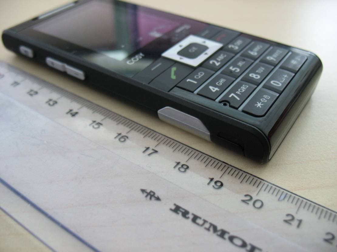
M9HCOSY3G
Oct 13, 2010COSY Phone 3G
Equipment Class
DXX - Part 15 Low Power Communication Device Transmitter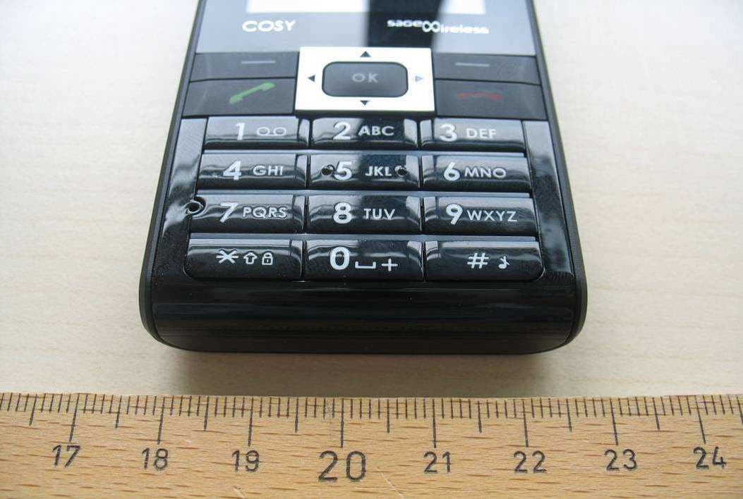
M9HCOSY2G
Sep 06, 2010COSY Phone 2G
Equipment Class
PCE - PCS Licensed Transmitter held to ear
M9HMOV001
Aug 18, 2010Handheld Top Up Terminal
Equipment Class
PCT - PCS Licensed Transmitter worn on body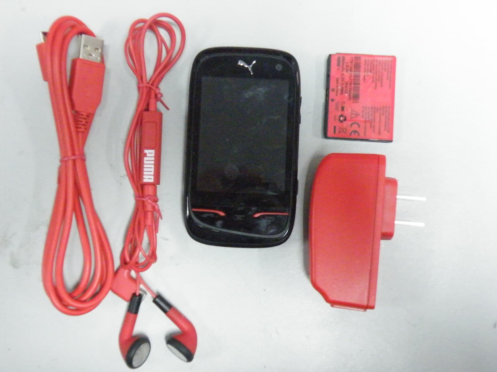
M9HPM1
Apr 26, 2010Mobile phone
Equipment Class
PCE - PCS Licensed Transmitter held to ear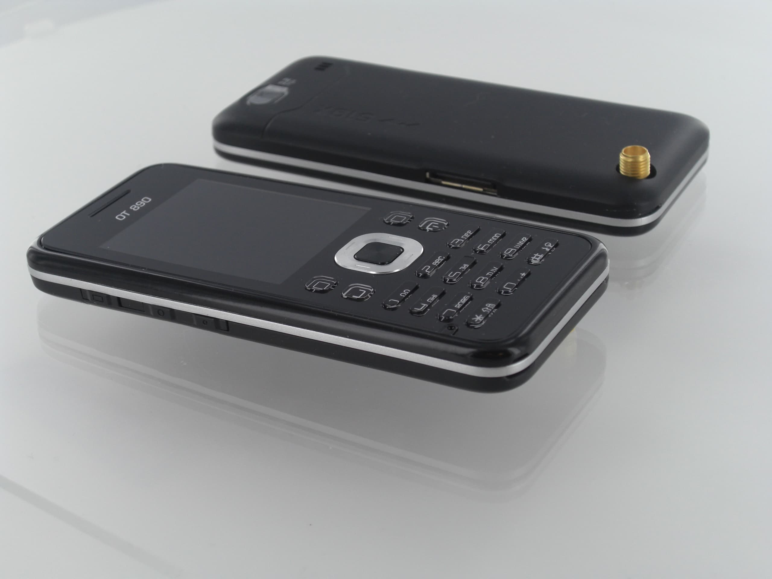
M9HOT8X0RF
Jan 31, 2010Network Measurement Device
Equipment Class
JBP - Part 15 Class B Computing Device Peripheral