M9H95OT208GSM 850/1900 Mobile Phone
Sagem WirelessApplication Details
- Equipment Class
- PCE - PCS Licensed Transmitter held to ear
- Date of Grant
- Mar 08, 2005
- Application Purpose
- Original Equipment
- Date of Application
- Mar 08, 2005
- Equipment Note
- GSM 850/1900 Mobile Phone
- Frequency Range
- 824.20000000 - 848.80000000
- Company
- Sagem Wireless
- Country
- France
Documents & Files
Document Text
Text extracted from the exhibit documents filed with the FCC. Open a document above to read the original.
Users Manual
1 Conformance Document SAGEM SA declares under its sole responsibility that the product GSM/DCS or PCS (depending on model) Type H2003 conforms to the requirements of the following EEC directives: EEC Directive 1999/5/CE Safety EN 60950: 2000 EMC EN 301 489-1 EN 301 489-7 Low voltage directive73/23/CEE Network 3GPP TS 51.010-1 with GCF-CC v3.8.1 included Requirements GT01 v 4.7.0 TBR 19 Edition 5 TBR 20 Edition 3 TBR 31 Edition 2 TBR 32 Edition 2 EN 301 419-1 EN 301511 v7.0.1 Health EN 50360 EN 50361 MYX-6 English.book Page 1 Mardi, 29. juillet 2003 9:38 09 2 FCC Conformance Document FCC Part 24 Network NAPRD03.ver 2.7.2 HealthDraft IEEE Std 1528-200x Exposure to Radio Frequency Signals - Your wireless handheld portable phone is a low power radio transmitter and receiver. When it is ON, it receives and also sends out frequency (RF) signals. - In August, 1996, the Federal Communications Commissions (FCC) adopted RF exposure guidelines with safety levels for handheld wireless phones. Those guidelines are consistent with the safety standards previously set by both U.S. and international standards bodies: ANSI C95.1 (1992)* NCPR Report 86 (1986)* ICNIRP (1996)* (*) American National Standards Institute; National Council on Radiation Protection and Measurements; International Commission and Non-Ionizing Radiation Protection. - Those standards were based on comprehensive and periodic evaluations of the relevant scientific literature. For example, over 120 scientists, engineers, and physicians from universities, government health agencies, and industry reviewed the available body of research to develop the ANSI Standard (C95.1). - The design of your phone complies with the FCC guidelines (and those standards). - For body worn operation, this phone has been tested and meets FCC RF exposure guidelines when used with an accessory that contains no metal and that positions the handset a minimum of 1.5 cm from the body. Use of other accessories may not ensure compliance with FCC RF exposure guidelines. MYX-6 English.book Page 2 Mardi, 29. juillet 2003 9:38 09 3 Menus Phonebook Contacts menu Messages Compose Inbox Outbox Drafts Options Memory Local info Camera Multimedia My Photos My Pictures My Sounds Memory WAP Games MegaBox Conquest Downloaded games Taquin Organiser Diary ToDo Calculator Converter Alarm Timer Settings Sounds Ring tones Vibrate Silent mode Beeps Recorder Look'n feel Skins Wallpapers Screensavers Camera Timer Click sound Format Languages Calls Calls forwarded View last calls Counters Display number Call waiting Auto redial Answer phone ALS Security Keypad locking PIN number PIN number 2 Phone code Confidentiality Operator Call barring Fixed dialling Cost Networks Others Car kit Data Energy saving Shortcuts Date/Time Control Display Time zone Summer time Services MYX-6 English.book Page 3 Mardi, 29. juillet 2003 9:38 09 4 Contents Page 3MENUS Page 9YOUR PHONE PACKAGE - ACCESSORIES Page 10DESCRIPTION Programmable keys and Shortcut keys Strap attachment Page 12NAVIGATION PRINCIPLES Page 13INITIAL SCREEN Page 14ACTIVATING YOUR PHONE Information on the SIM card Installing the SIM card and the battery Page 16USING YOUR PHONE Don't obstruct the antenna with your fingers Increase the efficiency of your phone Charging the battery Page 18PHONEBOOK Using the phonebook Contacts menu Options from a contact saved Sending a vCard Receiving a vCard MYX-6 English.book Page 4 Mardi, 29. juillet 2003 9:38 09 5 Contents Page 25MESSAGES Compose SMS Compose MMS Receiving messages Inbox Drafts Sending options Outbox Memory Local information Page 36CAMERA Take and send a photo Page 38MULTIMEDIA My Photos Display a photo Edit a photo My Pictures My Sounds Memory Page 42WAP The WAP Menu Configuring WAP parameters WAP Logging on Downloading sounds and images WAP Logging off GPRS MYX-6 English.book Page 5 Mardi, 29. juillet 2003 9:38 09 6 Contents Page 47GAMES Downloaded games Page 48ORGANISER Diary Calendar menu ToDo menu ToDo actions menu Sending a vCal Receiving a vCal Exchange of data with a PC Calculator Converter Alarm Timer Page 57SETTINGS Sounds Volume and ring tone Vibrate Silent mode Beeps Recorder Look’n feel Wallpapers Screensavers Camera Languages MYX-6 English.book Page 6 Mardi, 29. juillet 2003 9:38 09 7 Contents Calls Calls forwarded View last calls Counters Display number Call waiting Automatic redial Answer phone ALS Security Keypad locking PIN number PIN number 2 Phone code Confidentiality Operator Call barring Fixed dialling Cost Networks Others Car kit Data Energy saving Shortcuts MYX-6 English.book Page 7 Mardi, 29. juillet 2003 9:38 09 8 Contents Date / Time Control Display Time zone Summer time Page 77SERVICES Page 78TECHNICAL FEATURES Page 79WARRANTY Page 82TROUBLESHOOTING Page 87INDEX MYX-6 English.book Page 8 Mardi, 29. juillet 2003 9:38 09 9 Your phone package When you open the box, check that all items are present: 1 - Phone 2 - Charger 3 - Battery 4 - User guide 5 - CD (depending on model) Accessories You can also find (as an option) or order the following accessories: Hands-free kit (*) Additional battery Additional charger (*) Cable to connect your to a PC USB or serial port (*) CD driver (PC or Mac) to synchronise your phone with your PC Cigar lighter charger (*) Colored covers (*) These accessories are identical to the ones provided for the earlier 3000 series and MYX-5. 2 1 3 4 5 MYX-6 English.book Page 9 Mardi, 29. juillet 2003 9:38 09 10 Description Programmable keys and Shortcut keys Hold down: Stop Press briefly : In a call context: Reject a call - hang up In menus: Return to initial screen. Press briefly : Start phone In call context: Call - receiving a call - hands-free mode Left programmable key: (Function available depending on model) In initial screen: Access to certain functions (shortcuts) In menus: Cancel (or return) as indicated on the screen During call: Reduce volume Right programmable key: (Function available depending on model) In initial screen: Access to cer…
Text truncated - open the document above for the full version.
Users Manual
Technical Characteristics Please find hereunder the technical characteristics deleting and replacing the previous ones. Your mobile phone is a radio transmitter and receiver. It is designed and manufactured not to exceed the limits for exposure to radiofrequency (RF) energy set by the Federal Communications Commission of the U.S. Government. These limits are part of comprehensive guidelines and establish permitted levels of RF energy for the general population. The guidelines are based on standards that were developed by independent scientific organizations through periodic and thorough evaluation of scientific studies. The standards include a substantial safety margin designed to assure the safety of all persons, regardless of age and health. The exposure standard for mobile phones employs a unit of measurement known as the Specific Absorption Rate, or SAR. The SAR limit set by the FCC is 1.6 W/kg (*) . Tests for SAR are conducted using standard operating positions accepted by the FCC with the phone transmitting at its highest certified power level in all tested frequency bands. Although the SAR is determined at the highest certified power level, the actual SAR level of the phone while operating can be well below the maximum value. This is because the phone is designed to operate at multiple power levels so as to use only the power required to reach the network. In general, the closer you are to a wireless base station antenna, the lower the power output. Before a phone model is available for sale to the public, it must be tested and certified to the FCC that it does not exceed the limit established by the government-adopted requirement for safe exposure. The tests are performed in positions and locations (i.e., at the ear and worn on the body) as required by the FCC for each model. (*)In the United States and Canada, the SAR limit for mobile phones used by the public is 1.6 Watts/kilogram (W/kg) averaged over one gram of tissue. The standard incorporates a substantial margin of safety to give additional protection for the public and to account for any variations in measurements. Addenda_251940317_OT2X8_lu_en.fm Page 1 Jeudi, 3. février 2005 1:26 13 Technical Characteristics The highest SAR value for these model phones as reported to the FCC when tested for use at the ear and when worn on the body are: While there may be differences between the SAR levels of various phones and at various positions, they all meet the government requirement. The FCC has granted an Equipment Authorization for this model phone with all reported SAR levels evaluated as in compliance with the FCC RF exposure guidelines. SAR information on this model phone is on file with the FCC and can be found under the Display Grant section of http://www.fcc.gov/oet/fccid after searching on FCC ID relative to the phone model. SAR at the ear (W/kg)SAR worn of the body (W/kg) VersionFCC IDGSM 850PCS 1900GSM 850PCS 1900 OT208 or other applicable commercial names M9H95OT2080.5460.2310.4920.277 E Mobile Phones Division www.sagem.com/mobiles Le Ponant de Paris - 27, rue Leblanc - 75512 PARIS CEDEX 15 - FRANCE SAGEM SA - Société anonyme à directoire et conseil de surveillance Capital 35 500 000 € - 562 082 909 RCS PARIS Addenda_251940317_OT2X8_lu_en.fm Page 2 Jeudi, 3. février 2005 1:26 13
Cover Letter(s)
s e TELEPHONIE MOBILE MOBILE PHONES Ref : SCT TMO OT SPEC 082 A Date : 13/01/05 Centre de Saint Christophe - DTM 1. OT208 / MYX-7A DIFFERENCES DESCRIPTION 1.1 GENERALITY OT 208 is a derivative from MyX-7a (FCC ID: M9H95H03R3A). Main hardware differences between OT208 and myX-7a are suppression of the camera and adding of a connector/switch antenna at the previous camera location. The shielding of the camera is kept in order to keep the radio frequency specifications. 1.2 PART LIST DIFFERENTIAL OT208/MYX-7A Component removed: Camera Component added: Switchable connector Body (design) is different Document E Reproduction et divulgation interdites 4/20
RF Exposure Info
CETECOM ICT Services GmbH Untertuerkheimer Str. 6-10, 66117 Saarbruecken, Germany Phone: +49 (0) 681 598-0 Fax: -8475 SAR-Laboratory Phone: +49 (0) 681 598-8454 . As of 2005-02-14 Page 1 of 46 Accredited testing laboratory DAR registration number: TTI-P-G 166/98 Federal Motor Transport Authority (KBA) DAR registration number: KBA-P 00070-97 Appendix to test report 4-1462-12-03/04 Calibration data, Phantom certificate and detail information of the DASY4 System CETECOM ICT Services GmbH Calibration Data and Phantom Information to test report no.: 4-1462-12-03/04 As of 2005-02-14 Page 2 of 46 Table of Content 1 Calibration report “Probe ET3DV6” .................................................................................................................................... 3 2 Calibration report “Probe ET3DV6” .................................................................................................................................. 11 3 Calibration report “900 MHz System validation dipole” .................................................................................................. 19 4 Calibration report “1900 MHz System validation dipole .................................................................................................. 29 5 Calibration certificate of Data Aquisition Unit (DAE) ...................................................................................................... 38 6 Certificate of “SAM Twin Phantom V4.0/V4.0C” ........................................................................................................... 39 7 Application Note System Performance Check ................................................................................................................... 41 2005-02-14 CETECOM ICT Services GmbH Calibration Data and Phantom Information to test report no.: 4-1462-12-03/04 As of 2005-02-14 Page 3 of 46 1 Calibration report “Probe ET3DV6” CETECOM ICT Services GmbH Calibration Data and Phantom Information to test report no.: 4-1462-12-03/04 As of 2005-02-14 Page 4 of 46 CETECOM ICT Services GmbH Calibration Data and Phantom Information to test report no.: 4-1462-12-03/04 As of 2005-02-14 Page 5 of 46 CETECOM ICT Services GmbH Calibration Data and Phantom Information to test report no.: 4-1462-12-03/04 As of 2005-02-14 Page 6 of 46 CETECOM ICT Services GmbH Calibration Data and Phantom Information to test report no.: 4-1462-12-03/04 As of 2005-02-14 Page 7 of 46 CETECOM ICT Services GmbH Calibration Data and Phantom Information to test report no.: 4-1462-12-03/04 As of 2005-02-14 Page 8 of 46 CETECOM ICT Services GmbH Calibration Data and Phantom Information to test report no.: 4-1462-12-03/04 As of 2005-02-14 Page 9 of 46 CETECOM ICT Services GmbH Calibration Data and Phantom Information to test report no.: 4-1462-12-03/04 As of 2005-02-14 Page 10 of 46 CETECOM ICT Services GmbH Calibration Data and Phantom Information to test report no.: 4-1462-12-03/04 As of 2005-02-14 Page 11 of 46 2 Calibration report “Probe ET3DV6” CETECOM ICT Services GmbH Calibration Data and Phantom Information to test report no.: 4-1462-12-03/04 As of 2005-02-14 Page 12 of 46 CETECOM ICT Services GmbH Calibration Data and Phantom Information to test report no.: 4-1462-12-03/04 As of 2005-02-14 Page 13 of 46 CETECOM ICT Services GmbH Calibration Data and Phantom Information to test report no.: 4-1462-12-03/04 As of 2005-02-14 Page 14 of 46 CETECOM ICT Services GmbH Calibration Data and Phantom Information to test report no.: 4-1462-12-03/04 As of 2005-02-14 Page 15 of 46 CETECOM ICT Services GmbH Calibration Data and Phantom Information to test report no.: 4-1462-12-03/04 As of 2005-02-14 Page 16 of 46 CETECOM ICT Services GmbH Calibration Data and Phantom Information to test report no.: 4-1462-12-03/04 As of 2005-02-14 Page 17 of 46 CETECOM ICT Services GmbH Calibration Data and Phantom Information to test report no.: 4-1462-12-03/04 As of 2005-02-14 Page 18 of 46 CETECOM ICT Services GmbH Calibration Data and Phantom Information to test report no.: 4-1462-12-03/04 As of 2005-02-14 Page 19 of 46 3 Calibration report “900 MHz System validation dipole”
RF Exposure Info
CETECOM ICT Services GmbH Calibration Data and Phantom Information to test report no.: 4-1462-12-03/04 As of 2005-02-14 Page 20 of 46 CETECOM ICT Services GmbH Calibration Data and Phantom Information to test report no.: 4-1462-12-03/04 As of 2005-02-14 Page 21 of 46 CETECOM ICT Services GmbH Calibration Data and Phantom Information to test report no.: 4-1462-12-03/04 As of 2005-02-14 Page 22 of 46 CETECOM ICT Services GmbH Calibration Data and Phantom Information to test report no.: 4-1462-12-03/04 As of 2005-02-14 Page 23 of 46 CETECOM ICT Services GmbH Calibration Data and Phantom Information to test report no.: 4-1462-12-03/04 As of 2005-02-14 Page 24 of 46 CETECOM ICT Services GmbH Calibration Data and Phantom Information to test report no.: 4-1462-12-03/04 As of 2005-02-14 Page 25 of 46 CETECOM ICT Services GmbH Calibration Data and Phantom Information to test report no.: 4-1462-12-03/04 As of 2005-02-14 Page 26 of 46 CETECOM ICT Services GmbH Calibration Data and Phantom Information to test report no.: 4-1462-12-03/04 As of 2005-02-14 Page 27 of 46 CETECOM ICT Services GmbH Calibration Data and Phantom Information to test report no.: 4-1462-12-03/04 As of 2005-02-14 Page 28 of 46 CETECOM ICT Services GmbH Calibration Data and Phantom Information to test report no.: 4-1462-12-03/04 As of 2005-02-14 Page 29 of 46 4 Calibration report “1900 MHz System validation dipole CETECOM ICT Services GmbH Calibration Data and Phantom Information to test report no.: 4-1462-12-03/04 As of 2005-02-14 Page 30 of 46 CETECOM ICT Services GmbH Calibration Data and Phantom Information to test report no.: 4-1462-12-03/04 As of 2005-02-14 Page 31 of 46 CETECOM ICT Services GmbH Calibration Data and Phantom Information to test report no.: 4-1462-12-03/04 As of 2005-02-14 Page 32 of 46 CETECOM ICT Services GmbH Calibration Data and Phantom Information to test report no.: 4-1462-12-03/04 As of 2005-02-14 Page 33 of 46 CETECOM ICT Services GmbH Calibration Data and Phantom Information to test report no.: 4-1462-12-03/04 As of 2005-02-14 Page 34 of 46 CETECOM ICT Services GmbH Calibration Data and Phantom Information to test report no.: 4-1462-12-03/04 As of 2005-02-14 Page 35 of 46 CETECOM ICT Services GmbH Calibration Data and Phantom Information to test report no.: 4-1462-12-03/04 As of 2005-02-14 Page 36 of 46 CETECOM ICT Services GmbH Calibration Data and Phantom Information to test report no.: 4-1462-12-03/04 As of 2005-02-14 Page 37 of 46 CETECOM ICT Services GmbH Calibration Data and Phantom Information to test report no.: 4-1462-12-03/04 As of 2005-02-14 Page 38 of 46 5 Calibration certificate of Data Aquisition Unit (DAE) CETECOM ICT Services GmbH Calibration Data and Phantom Information to test report no.: 4-1462-12-03/04 As of 2005-02-14 Page 39 of 46 6 Certificate of “SAM Twin Phantom V4.0/V4.0C” CETECOM ICT Services GmbH Calibration Data and Phantom Information to test report no.: 4-1462-12-03/04 As of 2005-02-14 Page 40 of 46 CETECOM ICT Services GmbH Calibration Data and Phantom Information to test report no.: 4-1462-12-03/04 As of 2005-02-14 Page 41 of 46 7 Application Note System Performance Check 7.1.1.1 Purpose of system performance check The system performance check verifies that the system operates within its specifica-tions. System and operator errors can be detected and corrected. It is recommended that the system performance check is performed prior to any usage of the system in order to guarantee reproducible results. The measurement of the Specific Absorption Rate (SAR) is a complicated task and the result depends on the proper functioning of many components and the correct settings of many param-eters. Faulty results due to drift, failures or incorrect parameters might not be recognized, since they often look similar in distribution to the correct ones. The Dosimetric Assessment System DASY4 incorporates a system performance check procedure to test the proper functioning of the system. The system performance check uses normal SAR measurements in a simplified setup (the at section of the SAM Twin Phantom) with a well characterized source (a matched dipole at a specified distance). This setup was selected to give a high sensitivity to all parameters that might fail or vary over time (e.g., probe, liquid parameters, and software settings) and a low sensitivity to external effects inherent in the system (e.g., positioning uncertainty of the device holder). The system performance check does not replace the calibration of the components. The accuracy of the system performance check is not sufficient for calibration purposes. It is possible to calculate the field quite accurately in this simple setup; however, due to the open field situation some factors (e.g., laboratory re ections) cannot be accounted for. Calibrations in the at phantom are possible with transfer calibration methods, using either temperature probes or calibrated E-field probes. The system performance check also does not test the system performance for arbitrary field sit-uations encountered during real measurements of mobile phones. These checks are performed at SPEAG by testing the components under various conditions (e.g., spherical isotropy measurements in liquid, linearity measurements, temperature variations, etc.), the results of which are used for an error estimation of the system. The system performance check will indicate situations where the system uncertainty is exceeded due to drift or failure. 7.1.1.2 System Performance check procedure Preparation The conductivity should be measured before the validation and the measured liquid parameters must be entered in the software. If the measured values differ from targeted values in the dipole document, the liquid composition should be adjusted. If the validation is performed with slightly different (measured) liquid parameters, the expected SAR will also be different. See the application note about SAR sensitivities for an estimate of possible SAR deviations. Note …
Text truncated - open the document above for the full version.
RF Exposure Info
CETECOM ICT Services GmbH Untertuerkheimer Str. 6-10, 66117 Saarbruecken, Germany Phone: +49 (0) 681 598-0 Fax: -8475 SAR-Laboratory Phone: +49 (0) 681 598-8454 . As of 2005-03-07 Page 1 of 67 Accredited testing laboratory DAR registration number: TTI-P-G 081/94-D0 Federal Motor Transport Authority (KBA) DAR registration number: KBA-P 00070-97 Test report no. : 4-1462-12-03/04 Type identification : OT208 Test specification : IEEE P1528/D1.2 FCC-ID : M9H95OT208 Test specification : CETECOM ICT Services GmbH Test report no.: 4-1462-12-03/04 As of 2005-03-07 Page 2 of 67 Table of Contents 1 General Information............................................................................................................................................................... 3 1.1 Notes................................................................................................................................................................................ 3 1.1.1 Statement of Compliance ....................................................................................................................................... 3 1.2 Testing laboratory............................................................................................................................................................ 4 1.3 Details of applicant.......................................................................................................................................................... 4 1.4 Application details........................................................................................................................................................... 4 1.5 Test item .......................................................................................................................................................................... 5 1.6 Test specification(s) ........................................................................................................................................................ 6 1.6.1 RF exposure limits ................................................................................................................................................. 6 2 Technical test ......................................................................................................................................................................... 7 2.1 Summary of test results ................................................................................................................................................... 7 2.2 Test environment ............................................................................................................................................................. 7 2.3 Measurement and test set-up ........................................................................................................................................... 7 2.4 Measurement system ....................................................................................................................................................... 8 2.4.1 System Description ................................................................................................................................................ 8 2.4.2 Test environment ................................................................................................................................................... 9 2.4.3 Probe description ................................................................................................................................................... 9 2.4.4 Phantom description............................................................................................................................................. 10 2.4.5 Device holder description .................................................................................................................................... 10 2.4.6 Scanning procedure.............................................................................................................................................. 11 2.4.7 Spatial Peak SAR Evaluation............................................................................................................................... 12 2.4.8 Data Storage and Evaluation................................................................................................................................ 13 2.4.9 Test equipment utilized ........................................................................................................................................ 15 2.4.10 Tissue simulating liquids : dielectric properties................................................................................................... 16 2.4.11 Tissue simulating liquids : parameters ................................................................................................................. 17 2.4.12 Measurement uncertainty evaluation for SAR test .............................................................................................. 18 2.4.13 Measurement uncertainty evaluation for system validation................................................................................. 19 2.4.14 System validation................................................................................................................................................. 20 2.4.15 Validation procedure............................................................................................................................................ 21 2.5 Test results (Head and Body SAR)................................................................................................................................ 22 2.5.1 Description of test procedures.............................................................................................................................. 23 2.6 Test results (conducted power measurement)............…
Text truncated - open the document above for the full version.
Test Report
CETECOM ICT Services GmbH Radio Satellite Communication Untertürkheimer Straße 6-10 . D-66117 Saarbrücken Telefon: +49 (0)681 598-0 Telefax: - 9075 Test report No.: 4-1462-02-05/04 This test report consists of 79 pages Page 1 (79) Recognized by the Federal Communications Commission Anechoic Chamber Registration No.: 90462 (FCC) Anechoic Chamber Registration No.: 3463 (IC) TCB ID: DE 0001 Accredited by the German Accreditation Council DAR–Registration Number TTI–P–G 081/94-D0 Independent ETSI compliance test house ETSI Test Report No.: 4-1462-02-05/04 Applicant: Sagem SA Type: H2003a (myX-7a) Test Standards: FCC Part 22, 24 RSS132, 133 FCC ID: M9H95H03R3A CETECOM ICT Services GmbH Test report No.: 4-1462-02-05/04 Date: 2004-11-18 Page 2 (79) Table of Contents 1 GENERAL INFORMATION ....................................................................................................... 3 1.1 NOTES................................................................................................................................... 3 1.2 TESTING LABORATORY........................................................................................................... 3 1.3 DETAILS OF APPLICANT.......................................................................................................... 4 1.4 APPLICATION DETAILS............................................................................................................ 4 1.5 TEST ITEM.............................................................................................................................. 5 1.6 TEST STANDARDS................................................................................................................... 6 2 STATEMENT OF COMPLIANCE.............................................................................................. 7 2.1 SUMMARY OF MEASUREMENT RESULTS................................................................................... 7 2.1.1 PCS1900............................................................................................................................ 7 2.1.2 GSM 850............................................................................................................................ 7 3 MEASUREMENTS AND RESULTS............................................................................................ 8 3.1 PART PCS 1900..................................................................................................................... 8 3.1.1 RF Power Output................................................................................................................ 8 3.1.2 Frequency Stability........................................................................................................... 12 3.1.3 Radiated Emissions........................................................................................................... 15 3.1.4 Receiver Radiated Emissions............................................................................................. 21 3.1.5 Conducted Spurious Emissions.......................................................................................... 23 3.1.6 Block Edge Compliance.................................................................................................... 27 3.1.7 Occupied Bandwidth......................................................................................................... 30 3.2 PART GSM 850................................................................................................................... 37 3.2.1 RF Power Output.............................................................................................................. 37 3.2.2 Frequency Stability........................................................................................................... 40 3.2.3 Radiated Emissions.................…
Text truncated - open the document above for the full version.
Contact Information
Applicant
Francois CHAMBON(GM)
Test Firm
Cetecom ICT Services GmbHRalf Hoehn
Technical Specifications
| # | Rule Parts | Frequency Range | Power Output | Emission | Tolerance |
|---|---|---|---|---|---|
| 2 | 22H | 824.2 MHz - 848.8 MHz | 760.00 mW | 300KGXW | 0.017 ppm |
Other Applications from Sagem Wireless
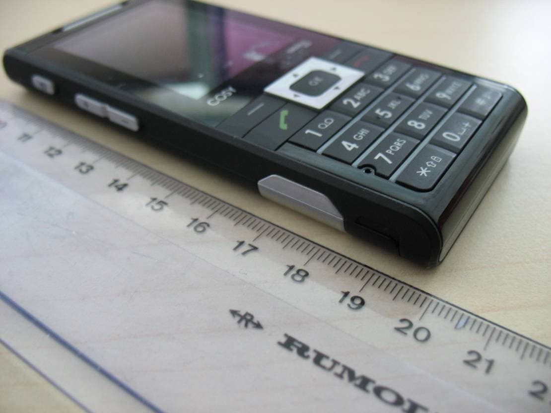
M9HCOSY3G
Oct 13, 2010COSY Phone 3G
Equipment Class
DXX - Part 15 Low Power Communication Device Transmitter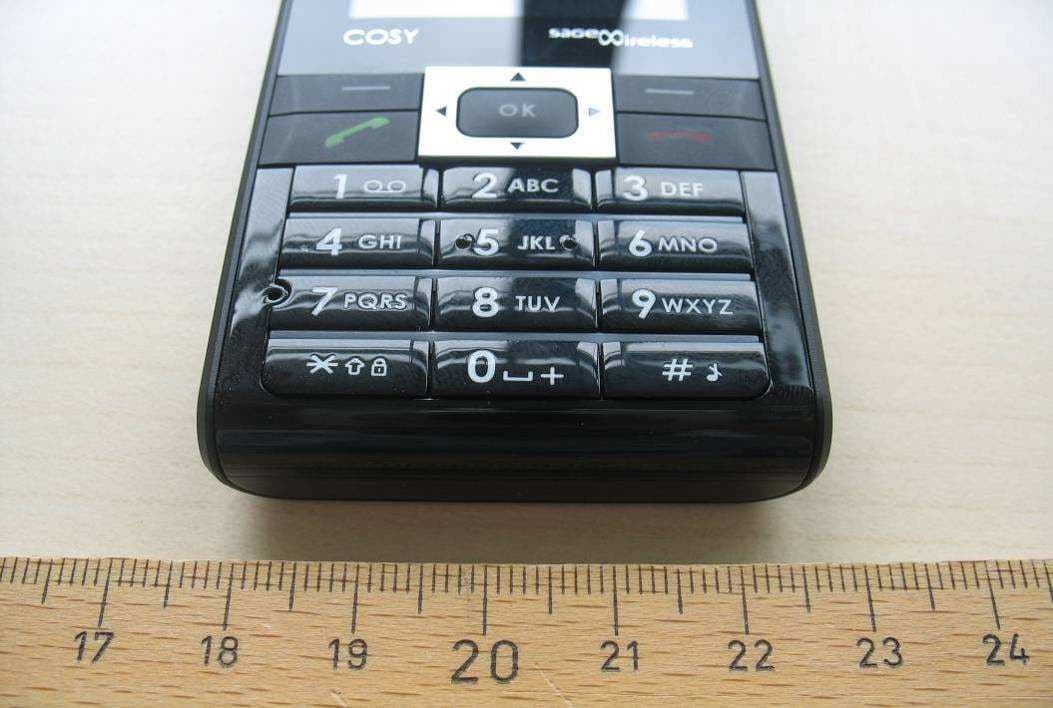
M9HCOSY2G
Sep 06, 2010COSY Phone 2G
Equipment Class
PCE - PCS Licensed Transmitter held to ear
M9HMOV001
Aug 18, 2010Handheld Top Up Terminal
Equipment Class
PCT - PCS Licensed Transmitter worn on body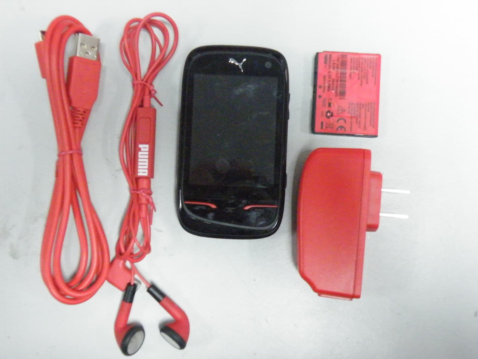
M9HPM1
Apr 26, 2010Mobile phone
Equipment Class
PCE - PCS Licensed Transmitter held to ear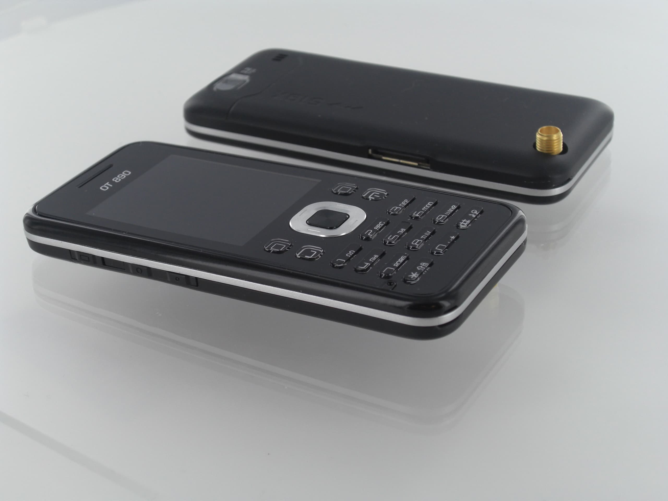
M9HOT8X0RF
Jan 31, 2010Network Measurement Device
Equipment Class
JBP - Part 15 Class B Computing Device Peripheral