M9H95P2002GSM 900/1900 Mobile Phone
Sagem Wireless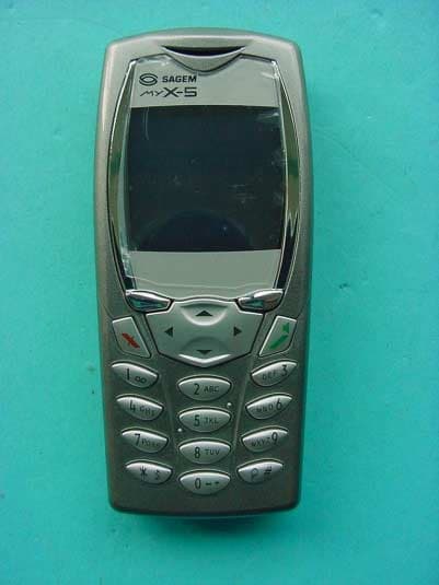
Click to zoom
Application Details
- Equipment Class
- PCE - PCS Licensed Transmitter held to ear
- Date of Grant
- Jan 16, 2003
- Application Purpose
- Original Equipment
- Date of Application
- Jan 16, 2003
- Equipment Note
- GSM 900/1900 Mobile Phone
- Frequency Range
- 1850.20000000 - 1909.80000000
- Company
- Sagem Wireless
- Country
- France
Documents & Files
Document Text
Text extracted from the exhibit documents filed with the FCC. Open a document above to read the original.
Users Manual
Safety information for wireless handheld phones Changing the covers S 2512XXXXX Add myX-5p_Safety Coques En.p6519/12/2002, 09:141 2 Use of your phone is subject to safety rules designed to protect the user and his or her environment. For body worn operation, this phone has been tested and meets FCC RF exposure guidelines when used with an accessory that contains no metal and that positions the handset a minimum of 1.5 cm from the body. Use of other accessories may not ensure compliance with FCC RF exposure guidelines. Exposure to Radio Frequency Signals n Your wireless handheld portable telephone is a low power radio transmitter and receiver. When it is ON, it receives and also sends out radio frequency (RF) signals. n In August, 1996, the Federal Communica- tions Commissions (FCC) adopted RF exposure guidelines with safety levels for handheld wireless phones. Those guidelines are consistent with the safety standards previously set by both U.S. and international standards bodies: ANSI C95.1 (1992) (∗) NCPR Report 86 (1986) (∗) ICNIRP (1996) (∗) (∗) American National Standards Institute; National Council on Radiation Protection and Measurements; International Commission on Non-Ionizing Radiation Protection. n Those standards were based on comprehensive and periodic evaluations of the relevant scientific literature. For example, over 120 scientists, engineers, and physicians from universities, government health agencies, and industry reviewed the available body of research to develop the ANSI Standard (C95.1). n The design of your phone complies with the FCC guidelines (and those standards). Phone Operation n Normal position: hold the phone as you would any other telephone with the antenna pointed up and over your shoulder. n Tips on efficient operation: for your phone to operate most efficiently: do not touch the antenna unnecessarily when the phone is in use. Contact with the antenna affects call quality and may cause the phone to operate at a higher power level than otherwise needed. Safety information 2512XXXXX Add myX-5p_Safety Coques En.p6519/12/2002, 09:142 3 Driving n Check the laws and regulations on the use of wireless telephones in the areas where you drive. Always obey them. Also, if using your phone while driving, please: •Give full attention to driving, driving safely is your first responsibility; •Use hands-free operation, if available; •Pull off the road and park before making or answering a call if driving conditions so require. Electronic Devices n Most modern electronic equipment is shielded from RF signals. However, certain electronic equipment may not be shielded against the RF signals from your wireless phone. n Some phone accessories allow to reduce the radiation interferences of the phone. Please contact your distributor. Pacemakers The Health Industry Manufacturers Asso- ciation recommends that a minimum separation of six (6) inches be maintained between a handheld wireless phone and a pacemaker to avoid potential interference with the pacema- ker. These recommendations are consis- tent with the independent research by and recommendations of Wireless Technology Research. Persons with pacemakers: •Should ALWAYS keep the phone more than six inches from their pacemaker when the phone is turned ON; •Should not carry the phone in a breast pocket; •Should use the ear opposite the pace- maker to minimize the potential for interference; •If you have any reason to suspect that interference is taking place, turn your phone OFF immediately. Safety information 2512XXXXX Add myX-5p_Safety Coques En.p6519/12/2002, 09:143 4 Hearing Aids Some digital wireless phones may interfere with some hearing aids. In the event of such interference, you may want to consult your service provider. Other Medical Devices If you use any other personal medical device, consult the manufacturer of your device to determine if they are adequately shielded from external RF energy. Your physician may be able to assist you in obtaining this information. Turn your phone OFF in health care facilities when any regulations posted in these areas instruct you to do so. Hospitals or health care facilities may be using equipment that could be sensitive to external RF energy. Vehicles RF signals may affect improperly installed or inadequately shielded electronic systems in motor vehicles. Check with the manufacturer or its representative regarding your vehicle. You should also consult the manufacturer of any equipment that has been added to your vehicle. Posted Facilities Turn your phone OFF in any facility where posted notices so require. Aircraft n FCC regulations prohibit using your phone while in the air. Switch OFF your phone before boarding an aircraft. Blasting Areas n To avoid interfering with blasting operations, turn your phone OFF when in a blasting area or in areas posted: Turn off two-way radio. Obey all signs and ins- tructions. Potentially Explosive Atmospheres n Turn your phone OFF when in any area with a potentially explosive atmosphere and obey all signs ans instructions. Sparks in such areas could cause an explosion or fire resulting in bodily injury or even death. Safety information 2512XXXXX Add myX-5p_Safety Coques En.p6519/12/2002, 09:144 5 n Areas with a potentially explosive atmosphere are often but not always clearly marked. They include fueling areas such as gasoline stations; below deck on boats; fuel or chemincal transfer or storage facilities; vehicles using liquefied petroleum gas (such as propane or bu- tane); areas where the air contains chemicals or particles, such as grain, dust, or metal powders; and any other area where you would normally be advised to turn off your vehicle engine. For Vehicles Equipped with an Air Bag n An air bag inflates with great force. DO NOT place objects, including both installed or portable wireless equipment, in the area over the air bag or in the air bag deployment area. If in-vehicle wireless equipment is improperly installed and the air bag in…
Text truncated - open the document above for the full version.
Users Manual
You have just purchased a SAGEM mobile and we congratulate on your choice. Your telephone can be used internationally in the various dual band networks (GSM/PCS 900/1900 MHz) depending on the roaming arrangements with your operator. We remind you that this telephone is approved to meet European standards. We recommend that you read this handbook carefully before using your telephone efficiently and in the best conditions. WARNING Depending on the configuration of the networks and the asso- ciated subscriber cards, some functions may not be available. Ensure that your SIM card is a 3 V SIM type that is compatible with your telephone. Inserting an incompatible card will be indicated by a message when your phone is switched on. Contact your operator. SAGEM is a trademark of SAGEM SA. AT is a registered trademark of Hayes Microcomputer Products Inc. Hates is a registered trademark of Hayes Microcomputer Products Inc. T9™ Text Input is a registered trademark of ©Tegic Communications Inc. T9 is protected by one or more of the following US patents: 5,818,437, 5,953,541, 5,187,480, 5,945,928, 6,011,554 and other patents are being applied for worldwide. 1 251206690_MYX-5p_en 21/10/02 13:59 Page 1 Services Phonebook Messages WAP Games Sounds Background Settings Calls Accessories Colours Wallpapers Screensavers Greeting msg Ring tones Vibrate Silent mode Beeps Date / time My objects Languages Networks Contrast Energy saving Shortcuts Reset settings Calls forwarded View last calls Counters Display numbers Call waiting Auto redial Answer phone number Local info Calculator Converter Alarm Timer Car kit Data Compose Inbox Drafts Options Memory Phonebook Menu MegaBox Conquest Downloaded games Security Keypad locking PIN number PIN number 2 Phone code Confidentiality Operator Call barring Fixed dialling 2 Menus 251206690_MYX-5p_en 21/10/02 13:59 Page 2 3 Contents Page 2MENUS Page 6YOUR PHONE PACKAGE - ACCESSORIES Page 7DESCRIPTION Programmable and shortcut keys Page 8 PRINCIPLES OF NAVIGATION Page 9HOME PAGE Page 10 to 13ACTIVATING YOUR TELEPHONE Information on SIM card Installing the SIM card and battery Changing the cover Charging the battery Page 14 to 19MY MOBILE IN 5 MINUTES How to get going PIN number Setting date and time Network First call - receiving a call Switching off Setting ring tone Page 20 to 24 PHONEBOOK Using the phonebook Phonebook menu Call groups Page 25 to 31MESSAGES Composing messages Using Mode T9 Inbox Drafts Sending options Memory 251206690_MYX-5p_en 21/10/02 13:59 Page 3 4 Contents Page 32 to 36WAP WAP Menus Configuring parameters Logging on Downloading objects Logging off GPRS Page 37GAMES MegaBox Conquest Downloaded games Page 38 to 39SOUNDS Ring tones Vibrate Silent mode Beeps Page 40 to 41BACKGROUND Colours Wallpapers Screensavers Greeting msg Page 42 to 45SETTINGS Date and time My objects Languages Networks Contrast Energy saving Shortcuts Reset settings 251206690_MYX-5p_en 21/10/02 13:59 Page 4 5 Contents Page 46 to 50CALLS Calls forwarded View last calls Counters Display numbers Call waiting Automatic redial Answer phone number Local info Page 51 to 54SECURITY Keypad locking PIN number PIN number 2 Phone code Confidentiality Operator code Call barring Fixed dialling Page 55 to 58ACCESSORIES Calculator Converter Alarm Timer Car kit Data Page 59SERVICES Page 60 to 61 TECHNICAL FEATURES Page 62 to 64WARRANTIES Page 65 to 69TROUBLESHOOTING Page 70 to 72INDEX 251206690_MYX-5p_en 21/10/02 13:59 Page 5 6 Your phone package - Accessories When you open the box,check that all the items are present: 1 - Telephone 2 - Mains charger 3 - Battery 4 - User manual Accessories You can also find (as an option) or order the following accessories: Pedestrian kit (*) Extra battery Extra charger (*) Office support (*) Cable to connect your to a PC USB or serial port (*) CD driver (PC or Mac) to synchronise your telephone with your PC Cigar lighter adapter (*) Colour cover Hands-free kit (*) (*) These accessories are identical to the ones provided for the earlier 900 and 3000 series. 1 2 3 4 251206690_MYX-5p_en 21/10/02 13:59 Page 6 7 Description Stop key: Hold down:Stop Press briefly: In a call context:Rejects a call - hung up In menus:Return to home page. Start key:Press briefly:Starts phone In call context:Call - reception of a call - hands-free mode Left programmable key: In home page:Access to certain functions (shortcuts) In menus:Cancel (or return) as indicated on screen During call:Reduces volume Right programmable key: In home page:Access to certain functions (shortcuts) In menus:Accept,choose as shown on screen During call:Increases volume Top key:Previous choice / reduce value / top Down key:Down choice / increase value / down Left key:Up input field / move left Right key:Down input field / move right * Key : Hold down:In home page:Silent mode Press briefly+ OK (right programmable key)activates or deactivates keypad locking In call reception mode:Short press stops ring tone In ring tone setting mode:Activates/deactivates ring tone # Key:Zoom mode (see message and WAP menus) Programmable keys and Shortcut keys 251206690_MYX-5p_en 21/10/02 14:00 Page 7 8 Principles of navigation These basic principles bring a great deal of intuitiveness to your tele- phone All the active areas on a white background (icon selector,pro- grammable keys,menu selector,choice list) Acceptby pressing the right programmable key4. Cancelby pressing the left programmable key3. The tabs on the sides at the down of the screen refer to the Programmable keys(and not to the left/right keys) In the menus a title bar indicates the down higher level. The down / top65navigation keys are used to navigate from one menu to the down within the same menu structure. The right programmable key4is used to go from a menu to a sub-menu. The left programmable key3is used to go from a sub- menu to a menu. The first menu level can be identified by a large animated icon in the centre of the screen. The second menu level can be identif…
Text truncated - open the document above for the full version.
External Photos
CETECOM ICT Services GmbH Test report no..: 3_3397-01-02/02Issue Date: 2002-10-30Page 58 (66) Photographs of the equipment CETECOM ICT Services GmbH Test report no..: 3_3397-01-02/02Issue Date: 2002-10-30Page 59 (66) Photographs of the equipment
Internal Photos
CETECOM ICT Services GmbH Test report no..: 3_3397-01-02/02Issue Date: 2002-10-30Page 60 (66) Photographs of the equipment CETECOM ICT Services GmbH Test report no..: 3_3397-01-02/02Issue Date: 2002-10-30Page 61 (66) Photographs of the equipment CETECOM ICT Services GmbH Test report no..: 3_3397-01-02/02Issue Date: 2002-10-30Page 62 (66) Photographs of the equipment CETECOM ICT Services GmbH Test report no..: 3_3397-01-02/02Issue Date: 2002-10-30Page 63 (66) Photographs of the equipment CETECOM ICT Services GmbH Test report no..: 3_3397-01-02/02Issue Date: 2002-10-30Page 64 (66) Photographs of the equipment
RF Exposure Info
CETECOM ICT Services GmbH Untertuerkheimer Str. 6-10, 66117 Saarbruecken, GermanyPhone: +49 (0) 681 598-0Fax: -8475 SAR-Laboratory Phone: +49 (0) 681 598-8454 . As of 2002.12.18 Page 1 of 40 Accredited testing laboratory DAR registration number: TTI-P-G 166/98 Federal Motor Transport Authority (KBA) DAR registration number: KBA-P 00070-97 Test report no. : 3-3397-1-4/02 Type identification : P2002 Test specification : Draft IEEE Std 1528-200X : OET Bulletin 65 FCC-ID: M9H95 P2002 Test specification : CETECOM ICT Services GmbH Test report no.: 3-3397-1-4/02 2002.12.18 Page 2 of 40 Table of Contents 1General Information............................................................................................................................................................... 3 1.1Notes .............................................................................................................................................................................. 3 1.1.1Statement of Compliance ....................................................................................................................................... 3 1.2Testing laboratory .......................................................................................................................................................... 4 1.3Details of applicant ........................................................................................................................................................ 4 1.4Application details ......................................................................................................................................................... 4 1.5Test item ........................................................................................................................................................................ 5 1.5.1Test specification(s) ............................................................................................................................................... 6 1.6RF exposure limits ......................................................................................................................................................... 6 2Technical test ......................................................................................................................................................................... 7 2.1Summary of test results.................................................................................................................................................. 7 2.2Test environment ........................................................................................................................................................... 7 2.3Measurement and test set-up.......................................................................................................................................... 7 2.4Measurement system...................................................................................................................................................... 8 2.4.1System Description ................................................................................................................................................ 8 2.4.2Test environment ................................................................................................................................................... 9 2.4.3Probe description ................................................................................................................................................... 9 2.4.4Phantom description ............................................................................................................................................ 10 2.4.5Device holder description .................................................................................................................................... 10 2.4.6Scanning procedure.............................................................................................................................................. 11 2.4.7Spatial Peak SAR Evaluation............................................................................................................................... 12 2.4.8Data Storage and Evaluation................................................................................................................................ 13 2.4.9Test equipment utilized........................................................................................................................................ 15 2.4.10Tissue simulating liquids : dielectric properties................................................................................................... 16 2.4.11Tissue simulating liquids : parameters ................................................................................................................. 17 2.4.12Measurement uncertainties .................................................................................................................................. 18 2.4.13System validation................................................................................................................................................. 19 2.4.14Validation procedure............................................................................................................................................ 20 2.5Test results (Head and Body SAR) .............................................................................................................................. 21 2.6Test results (conducted power measurement) .............................................................................................................. 21 Annex 1System performance verification ............................................................................................................................. 22 Annex 2Measurement results (printout from DASY TM ).............…
Text truncated - open the document above for the full version.
RF Exposure Info
CETECOM ICT Services GmbH Untertuerkheimer Str. 6-10, 66117 Saarbruecken, GermanyPhone: +49 (0) 681 598-0Fax: -8475 SAR-Laboratory Phone: +49 (0) 681 598-8454 . As of December 20, 2002Page 1 of 31 Accredited testing laboratory DAR registration number: TTI-P-G 166/98 Federal Motor Transport Authority (KBA) DAR registration number: KBA-P 00070-97 Appendix to the Report 3-3397-1-4/02 Calibration Data, Phantom Certificate and detail Information of the DASY 3 System Test specification : CETECOM ICT Services GmbH Calibration Data and Phantom Information; Report No.: 3-33397-1-4/02 As of December 20, 2002Page 2 of 31 Table of Content 1Calibration report “Probe ET3DV6”...............................................................................................................................3 2Calibration report “1900 MHz System validation dipole”..............................................................................................13 3Certificate of Conformity “SAM Twin Phantom V4.0/V4.0C”......................................................................................24 4Application Note Validation and system Check.............................................................................................................26 CETECOM ICT Services GmbH Calibration Data and Phantom Information; Report No.: 3-33397-1-4/02 As of December 20, 2002Page 3 of 31 1 Calibration report “Probe ET3DV6” CETECOM ICT Services GmbH Calibration Data and Phantom Information; Report No.: 3-33397-1-4/02 As of December 20, 2002Page 4 of 31 CETECOM ICT Services GmbH Calibration Data and Phantom Information; Report No.: 3-33397-1-4/02 As of December 20, 2002Page 5 of 31 CETECOM ICT Services GmbH Calibration Data and Phantom Information; Report No.: 3-33397-1-4/02 As of December 20, 2002Page 6 of 31 CETECOM ICT Services GmbH Calibration Data and Phantom Information; Report No.: 3-33397-1-4/02 As of December 20, 2002Page 7 of 31 CETECOM ICT Services GmbH Calibration Data and Phantom Information; Report No.: 3-33397-1-4/02 As of December 20, 2002Page 8 of 31 CETECOM ICT Services GmbH Calibration Data and Phantom Information; Report No.: 3-33397-1-4/02 As of December 20, 2002Page 9 of 31 CETECOM ICT Services GmbH Calibration Data and Phantom Information; Report No.: 3-33397-1-4/02 As of December 20, 2002Page 10 of 31 CETECOM ICT Services GmbH Calibration Data and Phantom Information; Report No.: 3-33397-1-4/02 As of December 20, 2002Page 11 of 31 CETECOM ICT Services GmbH Calibration Data and Phantom Information; Report No.: 3-33397-1-4/02 As of December 20, 2002Page 12 of 31 CETECOM ICT Services GmbH Calibration Data and Phantom Information; Report No.: 3-33397-1-4/02 As of December 20, 2002Page 13 of 31 2 Calibration report “1900 MHz System validation dipole” CETECOM ICT Services GmbH Calibration Data and Phantom Information; Report No.: 3-33397-1-4/02 As of December 20, 2002Page 14 of 31 CETECOM ICT Services GmbH Calibration Data and Phantom Information; Report No.: 3-33397-1-4/02 As of December 20, 2002Page 15 of 31 CETECOM ICT Services GmbH Calibration Data and Phantom Information; Report No.: 3-33397-1-4/02 As of December 20, 2002Page 16 of 31 CETECOM ICT Services GmbH Calibration Data and Phantom Information; Report No.: 3-33397-1-4/02 As of December 20, 2002Page 17 of 31 CETECOM ICT Services GmbH Calibration Data and Phantom Information; Report No.: 3-33397-1-4/02 As of December 20, 2002Page 18 of 31 CETECOM ICT Services GmbH Calibration Data and Phantom Information; Report No.: 3-33397-1-4/02 As of December 20, 2002Page 19 of 31 CETECOM ICT Services GmbH Calibration Data and Phantom Information; Report No.: 3-33397-1-4/02 As of December 20, 2002Page 20 of 31 CETECOM ICT Services GmbH Calibration Data and Phantom Information; Report No.: 3-33397-1-4/02 As of December 20, 2002Page 21 of 31 CETECOM ICT Services GmbH Calibration Data and Phantom Information; Report No.: 3-33397-1-4/02 As of December 20, 2002Page 22 of 31 CETECOM ICT Services GmbH Calibration Data and Phantom Information; Report No.: 3-33397-1-4/02 As of December 20, 2002Page 23 of 31 CETECOM ICT Services GmbH Calibration Data and Phantom Information; Report No.: 3-33397-1-4/02 As of December 20, 2002Page 24 of 31 3 Certificate of Conformity “SAM Twin Phantom V4.0/V4.0C” CETECOM ICT Services GmbH Calibration Data and Phantom Information; Report No.: 3-33397-1-4/02 As of December 20, 2002Page 25 of 31 CETECOM ICT Services GmbH Calibration Data and Phantom Information; Report No.: 3-33397-1-4/02 As of December 20, 2002Page 26 of 31 4 Application Note Validation and system Check 4.1.1.1 Purpose of validation The Validation and system check verify that the system operates within ist specifications. System and operator errors can be detected and corrected. It is recommended that the validation be performed prior to any usage of the system in order to guarantee reproducible results. The measurement of the Specific Absorption Rate (SAR) is a complicated task and the resultdepends on the proper functioning of many components and the correct settings of manyparameters. Faulty results due to drift, failures or incorrect parameters might not berecognized, since they often look similar in distribution to the correct ones. The DosimetricAssessment System DASY3 incorporates a validation procedure to test the properfunctioning of the system. The system validation uses normal SAR measurements in asimplified setup (the flat phantom section of the Generic Twin Phantom) with a wellcharacterized source (a matched dipole of a specified distance). This setup was selected to give a high sensitivity to all parameters that might fail or vary over time (e.g. probe, liquid parameters, and software settings) and a low sensitivity to external effects inherent in the system (e.g. positioning uncertainty of the device holder). The validation does not replace the calibration of the components. The accuracy of the validation is not sufficient for calibration purposes. It…
Text truncated - open the document above for the full version.
RF Exposure Info
CETECOM ICT Services GmbH Untertuerkheimer Str. 6-10, 66117 Saarbruecken, GermanyPhone: +49 (0) 681 598-0Fax: -8475 SAR-Laboratory Phone: +49 (0) 681 598-8454 . As of September 20, 2002Page 1 of 30 Accredited testing laboratory DAR registration number: TTI-P-G 166/98 Federal Motor Transport Authority (KBA) DAR registration number: KBA-P 00070-97 Appendix to the Report 3-3397-1-4/02 Photo documentation Test specification : CETECOM ICT Services GmbH Photo documentation Report No.: 3-3397-1-4/02 As of September 20, 2002Page 2 of 30 Annex 3 Photo documentation Picture no. 1 Measurement System DASY 3 CETECOM ICT Services GmbH Photo documentation Report No.: 3-3397-1-4/02 As of September 20, 2002Page 3 of 30 Picture no. 2 P2002 front touch left CETECOM ICT Services GmbH Photo documentation Report No.: 3-3397-1-4/02 As of September 20, 2002Page 4 of 30 Picture no. 3 P2002 side touch left CETECOM ICT Services GmbH Photo documentation Report No.: 3-3397-1-4/02 As of September 20, 2002Page 5 of 30 Picture no. 4 P2002 rear touch left CETECOM ICT Services GmbH Photo documentation Report No.: 3-3397-1-4/02 As of September 20, 2002Page 6 of 30 Picture no. 5 P2002 front tilted left CETECOM ICT Services GmbH Photo documentation Report No.: 3-3397-1-4/02 As of September 20, 2002Page 7 of 30 Picture no. 6 P2002 side tilted left CETECOM ICT Services GmbH Photo documentation Report No.: 3-3397-1-4/02 As of September 20, 2002Page 8 of 30 Picture no. 7 P2002 rear tilted left CETECOM ICT Services GmbH Photo documentation Report No.: 3-3397-1-4/02 As of September 20, 2002Page 9 of 30 Picture no. 8 P2002 front touch right CETECOM ICT Services GmbH Photo documentation Report No.: 3-3397-1-4/02 As of September 20, 2002Page 10 of 30 Picture no. 9 P2002 side touch left CETECOM ICT Services GmbH Photo documentation Report No.: 3-3397-1-4/02 As of September 20, 2002Page 11 of 30 Picture no. 10 P2002 rear touch left CETECOM ICT Services GmbH Photo documentation Report No.: 3-3397-1-4/02 As of September 20, 2002Page 12 of 30 Picture no. 11 P2002 front tilted right CETECOM ICT Services GmbH Photo documentation Report No.: 3-3397-1-4/02 As of September 20, 2002Page 13 of 30 Picture no. 12 P2002 side tilted right CETECOM ICT Services GmbH Photo documentation Report No.: 3-3397-1-4/02 As of September 20, 2002Page 14 of 30 Picture no. 13 P2002 rear tilted right CETECOM ICT Services GmbH Photo documentation Report No.: 3-3397-1-4/02 As of September 20, 2002Page 15 of 30 Picture no. 14 P2002 flat front CETECOM ICT Services GmbH Photo documentation Report No.: 3-3397-1-4/02 As of September 20, 2002Page 16 of 30 Picture no. 15 P2002 flat front 15 mm CETECOM ICT Services GmbH Photo documentation Report No.: 3-3397-1-4/02 As of September 20, 2002Page 17 of 30 Picture no. 16 P2002 flat front CETECOM ICT Services GmbH Photo documentation Report No.: 3-3397-1-4/02 As of September 20, 2002Page 18 of 30 Picture no. 17 P2002 flat rear CETECOM ICT Services GmbH Photo documentation Report No.: 3-3397-1-4/02 As of September 20, 2002Page 19 of 30 Picture no. 18 P2002 flat rear 15 mm CETECOM ICT Services GmbH Photo documentation Report No.: 3-3397-1-4/02 As of September 20, 2002Page 20 of 30 Picture no. 19 P2002 flat rear CETECOM ICT Services GmbH Photo documentation Report No.: 3-3397-1-4/02 As of September 20, 2002Page 21 of 30 Picture no. 20 P2002 front CETECOM ICT Services GmbH Photo documentation Report No.: 3-3397-1-4/02 As of September 20, 2002Page 22 of 30 Picture no. 21 P2002 left side CETECOM ICT Services GmbH Photo documentation Report No.: 3-3397-1-4/02 As of September 20, 2002Page 23 of 30 Picture no. 22 P2002 right side CETECOM ICT Services GmbH Photo documentation Report No.: 3-3397-1-4/02 As of September 20, 2002Page 24 of 30 Picture no. 23 P2002 rear CETECOM ICT Services GmbH Photo documentation Report No.: 3-3397-1-4/02 As of September 20, 2002Page 25 of 30 Picture no. 24 P2002 rear with battery CETECOM ICT Services GmbH Photo documentation Report No.: 3-3397-1-4/02 As of September 20, 2002Page 26 of 30 Picture no. 25 P2002 rear without battery CETECOM ICT Services GmbH Photo documentation Report No.: 3-3397-1-4/02 As of September 20, 2002Page 27 of 30 Picture no. 26 battery rear CETECOM ICT Services GmbH Photo documentation Report No.: 3-3397-1-4/02 As of September 20, 2002Page 28 of 30 Picture no. 27 battery front CETECOM ICT Services GmbH Photo documentation Report No.: 3-3397-1-4/02 As of September 20, 2002Page 29 of 30 Picture no. 28 liquid depth head 1900 MHz CETECOM ICT Services GmbH Photo documentation Report No.: 3-3397-1-4/02 As of September 20, 2002Page 30 of 30 Picture no. 29 liquid depth body 1900 MHz
Test Report
CETECOM ICT Services GmbH Radio Satellite Communication Untertürkheimer Straße 6-10 . D-66117 SaarbrückenTelefon: +49 (0)681 598-9100Telefax: -9075 RSC11issue test report consist of 66 PagesPage 1 (66) BLUETOOTH TM is a trademark owned by Bluetooth SIG, Inc. and licensed to CETECOM TTI-P-G-166/98-30 Accredited Bluetooth Test Facility (BQTF) Test report no.: 3_3397-01-02/02 FCC Part 24 P2002 FCC ID: M9H 95 P2002 CETECOM – ICT Services GmbH Untertürkheimerstr. 6-10 66117 Saa…
Text truncated - open the document above for the full version.
Contact Information
Applicant
Francois CHAMBON(GM)
Test Firm
Cetecom ICT Services GmbHRalf Hoehn
Technical Specifications
| # | Rule Parts | Frequency Range | Power Output | Emission | Tolerance |
|---|---|---|---|---|---|
| 1 | 24E | 1.85 GHz - 1.91 GHz | 760.00 mW | 300KGXW | 0.0250000000 ppm |
Other Applications from Sagem Wireless
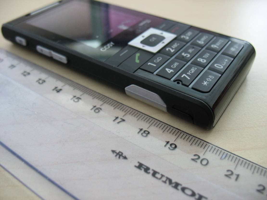
M9HCOSY3G
Oct 13, 2010COSY Phone 3G
Equipment Class
DXX - Part 15 Low Power Communication Device Transmitter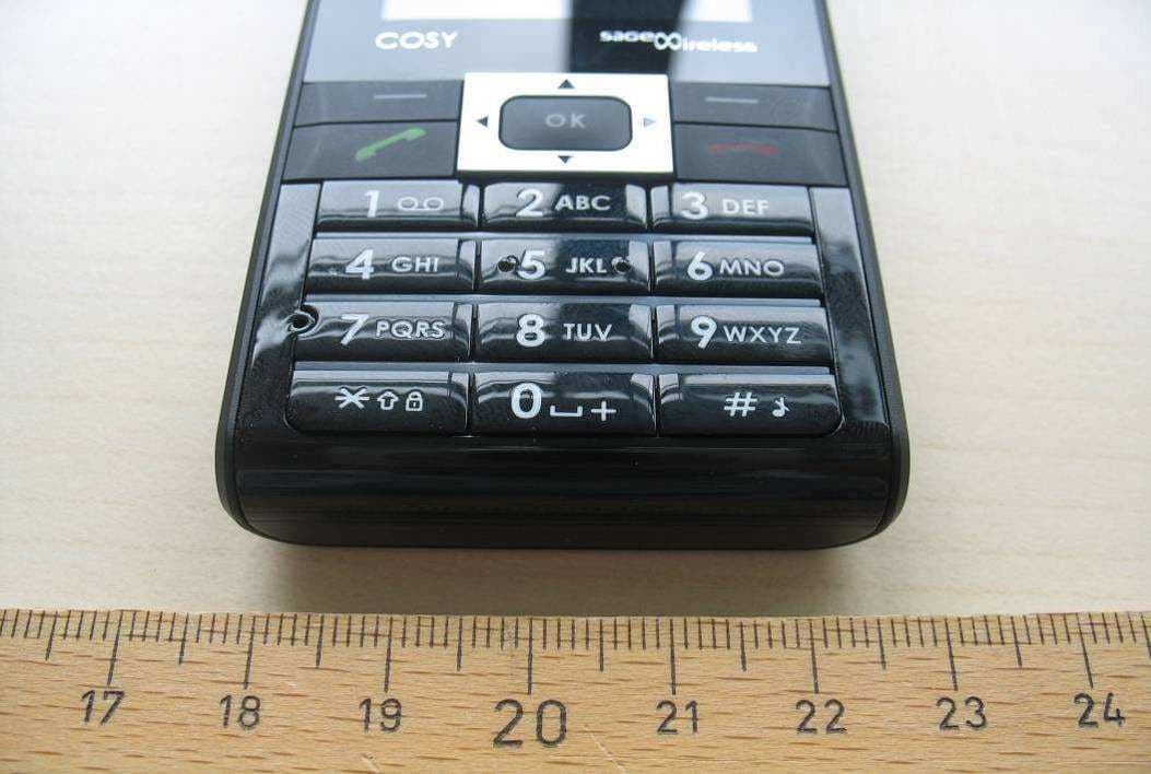
M9HCOSY2G
Sep 06, 2010COSY Phone 2G
Equipment Class
PCE - PCS Licensed Transmitter held to ear
M9HMOV001
Aug 18, 2010Handheld Top Up Terminal
Equipment Class
PCT - PCS Licensed Transmitter worn on body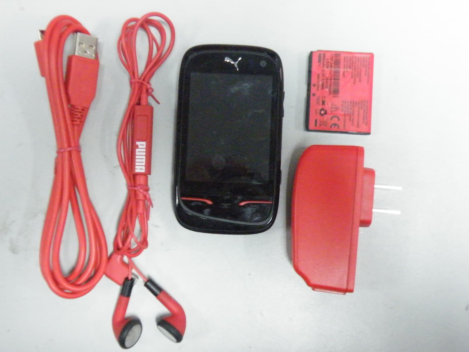
M9HPM1
Apr 26, 2010Mobile phone
Equipment Class
PCE - PCS Licensed Transmitter held to ear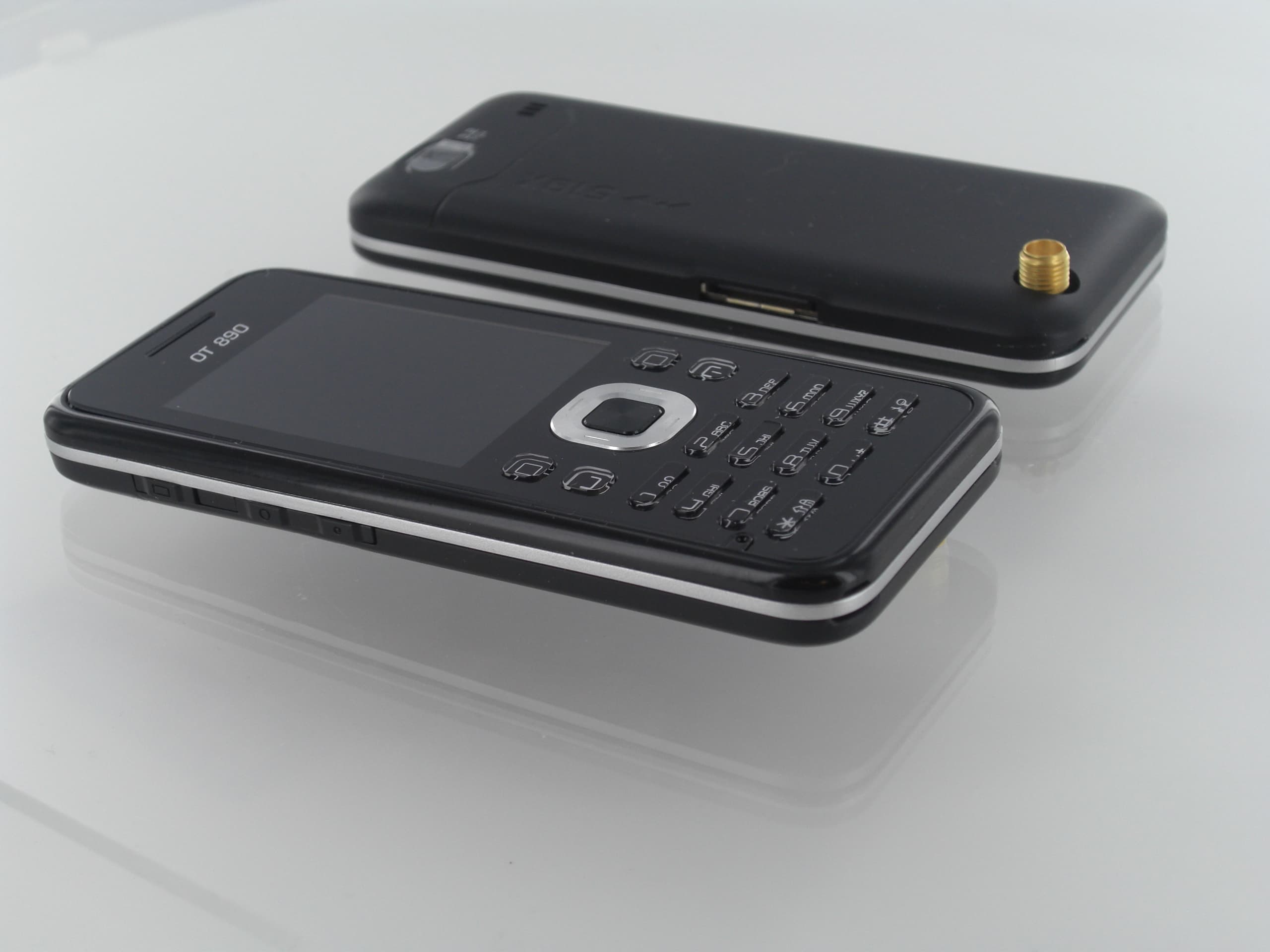
M9HOT8X0RF
Jan 31, 2010Network Measurement Device
Equipment Class
JBP - Part 15 Class B Computing Device Peripheral