M9H95X2AMRGSM 850/1900 Mobile Phone
Sagem Wireless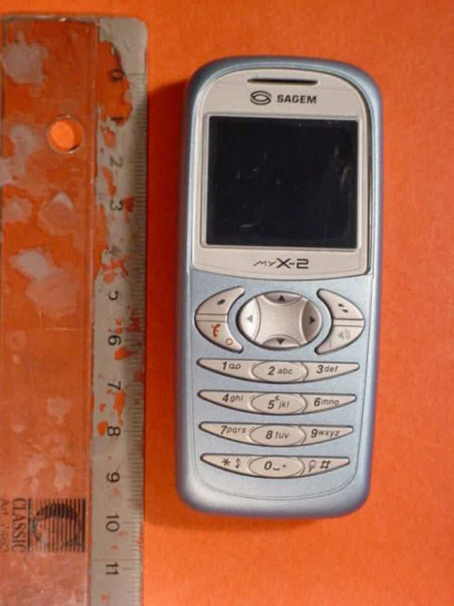
Click to zoom
Application Details
- Equipment Class
- PCE - PCS Licensed Transmitter held to ear
- Date of Grant
- Sep 02, 2004
- Application Purpose
- Original Equipment
- Date of Application
- Sep 02, 2004
- Equipment Note
- GSM 850/1900 Mobile Phone
- Frequency Range
- 824.20000000 - 848.80000000
- Company
- Sagem Wireless
- Country
- France
Documents & Files
Document Text
Text extracted from the exhibit documents filed with the FCC. Open a document above to read the original.
Users Manual
1 Conformance Document SAGEM SA declare under its sole responsibility that the product Dual Band GSM 850/PCS Type B2003 conforms to the requirements of the following EEC directives: EEC Directive 1999/5/CE SafetyEN 60950 EMCEN 301 489-1 EN 301 489-7 This phone is marked CE in accordance with RTTE directive with CEM EN301489-7 norme implementation, suited to the 850/1900 work frequencies. It is not intended to be used in Europe. Low voltage directive 73/23/CEE Network 3GPP TS 51.010-1 v 5.4 .0 Requirements GT01 v 4.7.0 TBR 19 Edition 5 TBR 20 Edition 3 TBR 31 Edition 2 TBR 32 Edition 2 EN 301 419-1 EN 301511 FCC Conformance Document FCC Part 24 Network NAPRD03.ver 2.8.0 HealthDraft IEEE Std 1528-200x 251312906 My-X2a English.book Page 1 Mercredi, 9. juillet 2003 1:46 13 2 Safety Information for Wireless handled phones Use of your phone is subject to safety rules designed to protect the user and his or her environment. Exposure to Radio Frequency Signals - Your wireless handheld portable phone is a low power radio transmitter and receiver. When it is ON, it receives and also sends out frequency (RF) signals. - In August, 1996, the Federal Communications Commissions (FCC) adopted RF exposure guidelines with safety levels for handheld wireless phones. Those guidelines are consistent with the safety standards previously set by both U.S. and international standards bodies: ANSI C95.1 (1992) (*) NCPR Report 86 (1986) (*) ICNIRP (1996) (*) - Those standards were based on comprehensive and periodic evaluations of the relevant scientific literature. For example, over 120 scientists, engineers, and physicians from universities, government health agencies, and industry reviewed the available body of research to develop the ANSI Standard (C95.1). - The design of your phone complies with the FCC guidelines (and those standards). - For body worn operation, this phone has been tested and meets FCC RF exposure guidelines when used with an accessory that contains no metal and that positions the handset a minimum of 1.5 cm from the body. Use of other accessories may not ensure compliance with FCC RF exposure guidelines. Phone Operation - Normal position: hold the phone as you would any other phone with the upper zone (back of the LCD display) pointed up and over your shoulder. - Tips on efficient operation: for your phone to operate most efficiently: do not touch cover unnecessarily the top part of the phone with your hand. This would cover the integrated antenna and affect call quality and may cause the phone to operate at a higher power level than otherwise needed. (*) American National Standards Institute; National Council on Radiation Protection and Measurements; International Commission and Non-Ionizing Radiation Protection. 251312906 My-X2a English.book Page 2 Mercredi, 9. juillet 2003 1:46 13 3 Safety Information for Wireless handled phones Driving - Check the laws and regulations on the use of wireless phones in the areas where you drive. Always obey them. Also, if using your phone while driving while driving please: • Give full attention of driving, driving safely is your first responsibility • Use hands-free operation, if available • Pull off the road and park before making or answering a call if driving conditions so require. Electronic Devices - Most modern electronic equipment is shielded from RF signals. However, certain electronic equipment may not be shielded against the RF signals from your wireless phone. - Some phone accessories allow to reduce the radiation interferences of the phone. Please contact your distributor. Pacemakers The Health Industry Manufacturers Association recommends that a minimum separation of six (6”) inches be maintained between a handheld wireless phone and a pacemaker to avoid potential interference with the pacemaker. These recommendations are consistent with the independent research by and recommendations of Wireless Technology Research. Persons with pacemakers: - Should ALWAYS keep the phone more than six inches from their pacemaker when the phone is turned ON - Should not carry the phone in the breast pocket - Should use the ear opposite to the pacemaker to minimize the potential for interference - If you have any reason to suspect that interference is taking place, turn your phone OFF immediately. Hearing Aids Some digital wireless phones may interfere with some hearing aids. In the event of such interference, you may want to consult your service provider. 251312906 My-X2a English.book Page 3 Mercredi, 9. juillet 2003 1:46 13 4 Safety Information for Wireless handled phones Other Medical Devices If you use any other personal medical device, consult the manufacturer of your device to determine if they are adequately shielded from external RF energy. Your physician may be able to assist you in obtaining this information. Turn your phone OFF in health care facilities when any regulations posted in these areas instruct you to do so. Hospitals or health care facilities may be using equipment that could be sensitive to sensitive external RF energy. Vehicles RF signals may affect improperly installed or inadequately shielded electronic systems in motor vehicles. Check with the manufacturer or its representative regarding your vehicle. You should also consult the manufacturer of any equipment that has been added to your vehicle. Posted Facilities Turn your phone OFF in any facility where posted notices so require. Aircraft FCC regulations prohibit using your phone while in the air. Switch OFF your phone before boarding an aircraft. Blasting Areas To avoid any interfering with blasting operations, turn your phone OFF when in a “blasting area” or in areas posted: “Turn off two-way radio”. Obey all signs and instructions. 251312906 My-X2a English.book Page 4 Mercredi, 9. juillet 2003 1:46 13 5 Safety Information for Wireless handled phones Potentially Explosive Atmospheres - Turn your phone OFF when in any area with a potentially explosive atmosphere and obey all signs …
Text truncated - open the document above for the full version.
External Photos
CETECOM ICT Services GmbH Test report no.: 4-0902-11-01/03 As of August 6, 2003Page 56 of 89 Picture no. 2 DUT - front view CETECOM ICT Services GmbH Test report no.: 4-0902-11-01/03 As of August 6, 2003Page 57 of 89 Picture no. 3 DUT - side view CETECOM ICT Services GmbH Test report no.: 4-0902-11-01/03 As of August 6, 2003Page 58 of 89 Picture no. 4 DUT - connector for accessories CETECOM ICT Services GmbH Test report no.: 4-0902-11-01/03 As of August 6, 2003Page 59 of 89 Picture no. 5 DUT - rear view
ID Label/Location Info
Sagem SA Centre de Saint Christophe - DTM TELEPHONIE MOBILE MOBILE PHONES 05/11/03 DocumentSAGEM SA Reproduction et divulgation interdites11/27 2.1.3 Label Informations CETECOM ICT Services GmbH Test report no..: 4_0902-11-02/03Issue Date: 2003-08-07Page 149 (167) Photographs of the equipment
Internal Photos
CETECOM ICT Services GmbH Test report no..: 4_0902-11-02/03Issue Date: 2003-08-07Page 148 (167) Photographs of the equipment CETECOM ICT Services GmbH Test report no..: 4_0902-11-02/03Issue Date: 2003-08-07Page 149 (167) Photographs of the equipment CETECOM ICT Services GmbH Test report no..: 4_0902-11-02/03Issue Date: 2003-08-07Page 150 (167) Photographs of the equipment CETECOM ICT Services GmbH Test report no..: 4_0902-11-02/03Issue Date: 2003-08-07Page 151 (167) Photographs of the equipment CETECOM ICT Services GmbH Test report no..: 4_0902-11-02/03Issue Date: 2003-08-07Page 152 (167) Photographs of the equipment CETECOM ICT Services GmbH Test report no..: 4_0902-11-02/03Issue Date: 2003-08-07Page 153 (167) Photographs of the equipment CETECOM ICT Services GmbH Test report no..: 4_0902-11-02/03Issue Date: 2003-08-07Page 154 (167) Photographs of the equipment CETECOM ICT Services GmbH Test report no..: 4_0902-11-02/03Issue Date: 2003-08-07Page 155 (167) Photographs of the equipment
Parts List/Tune Up Info
Tune-up procedure for B2003A During manufacturing each phone will be individually calibrated. The measurement is done in a fully calibrated setup, which is based on a Wavetek 4200 base station simulator (system tester). Furthermore, the highest power level is verified afterwards in a call measurement on three channels (low, mid and high) in each Band (GSM850 and PCS1900) Procedure : 1. Set the phone to operational voltage (3.9V) and on one certain channel (TCH 190 for GSM 850 Band and TCH 661 for PCS1900 Band) in Burn-In Mode (Test Software, the phone is in emission mode only). 2. The actual power is measured at 2 different power levels. 3. Gain factor is adjusted for PL min 4. Thanks to Step 2 and 3, the gain factors of each individual phone are calculated and stored in each phone individually. 5. All power level are measured for checking. The user has no possibility to change these settings later on.
RF Exposure Info
CETECOM ICT Services GmbH Untertuerkheimer Str. 6-10, 66117 Saarbruecken, GermanyPhone: +49 (0) 681 598-0Fax: -8475 SAR-Laboratory Phone: +49 (0) 681 598-8454 . As of August 6, 2003Page 1 of 41 Accredited testing laboratory DAR registration number: TTI-P-G 166/98 Federal Motor Transport Authority (KBA) DAR registration number: KBA-P 00070-97 Appendix to the Report 4-0902-11-01/03 Calibration Data, Phantom Certificate and detail Information of the DASY 3 System CETECOM ICT Services GmbH Calibration Data and Phantom Information; Report No.: 4-0902-11-01/03 As of August 6, 2003Page 2 of 41 Table of Content 1.Calibration report “Probe ET3DV6”.............................................................................................................................................3 2.Calibration report “1900 MHz System validation dipole”.......................................................................................................14 3.Calibration report “900 MHz System validation dipole”.........................................................................................................24 4.Calibration certificate of Data Aquisition Unit (DAE)..............................................................................................................33 5.Certificate of Conformity “SAM Twin Phantom V4.0/V4.0C”................................................................................................34 6.Application Note Validation and system Check........................................................................................................................36 CETECOM ICT Services GmbH Calibration Data and Phantom Information; Report No.: 4-0902-11-01/03 As of August 6, 2003Page 3 of 41 1. Calibration report “Probe ET3DV6” CETECOM ICT Services GmbH Calibration Data and Phantom Information; Report No.: 4-0902-11-01/03 As of August 6, 2003Page 4 of 41 CETECOM ICT Services GmbH Calibration Data and Phantom Information; Report No.: 4-0902-11-01/03 As of August 6, 2003Page 5 of 41 CETECOM ICT Services GmbH Calibration Data and Phantom Information; Report No.: 4-0902-11-01/03 As of August 6, 2003Page 6 of 41 CETECOM ICT Services GmbH Calibration Data and Phantom Information; Report No.: 4-0902-11-01/03 As of August 6, 2003Page 7 of 41 CETECOM ICT Services GmbH Calibration Data and Phantom Information; Report No.: 4-0902-11-01/03 As of August 6, 2003Page 8 of 41 CETECOM ICT Services GmbH Calibration Data and Phantom Information; Report No.: 4-0902-11-01/03 As of August 6, 2003Page 9 of 41 CETECOM ICT Services GmbH Calibration Data and Phantom Information; Report No.: 4-0902-11-01/03 As of August 6, 2003Page 10 of 41 CETECOM ICT Services GmbH Calibration Data and Phantom Information; Report No.: 4-0902-11-01/03 As of August 6, 2003Page 11 of 41 CETECOM ICT Services GmbH Calibration Data and Phantom Information; Report No.: 4-0902-11-01/03 As of August 6, 2003Page 12 of 41 CETECOM ICT Services GmbH Calibration Data and Phantom Information; Report No.: 4-0902-11-01/03 As of August 6, 2003Page 13 of 41 CETECOM ICT Services GmbH Calibration Data and Phantom Information; Report No.: 4-0902-11-01/03 As of August 6, 2003Page 14 of 41 2. Calibration report “1900 MHz System validation dipole” CETECOM ICT Services GmbH Calibration Data and Phantom Information; Report No.: 4-0902-11-01/03 As of August 6, 2003Page 15 of 41 CETECOM ICT Services GmbH Calibration Data and Phantom Information; Report No.: 4-0902-11-01/03 As of August 6, 2003Page 16 of 41 CETECOM ICT Services GmbH Calibration Data and Phantom Information; Report No.: 4-0902-11-01/03 As of August 6, 2003Page 17 of 41 CETECOM ICT Services GmbH Calibration Data and Phantom Information; Report No.: 4-0902-11-01/03 As of August 6, 2003Page 18 of 41 CETECOM ICT Services GmbH Calibration Data and Phantom Information; Report No.: 4-0902-11-01/03 As of August 6, 2003Page 19 of 41 CETECOM ICT Services GmbH Calibration Data and Phantom Information; Report No.: 4-0902-11-01/03 As of August 6, 2003Page 20 of 41 CETECOM ICT Services GmbH Calibration Data and Phantom Information; Report No.: 4-0902-11-01/03 As of August 6, 2003Page 21 of 41 CETECOM ICT Services GmbH Calibration Data and Phantom Information; Report No.: 4-0902-11-01/03 As of August 6, 2003Page 22 of 41 CETECOM ICT Services GmbH Calibration Data and Phantom Information; Report No.: 4-0902-11-01/03 As of August 6, 2003Page 23 of 41 CETECOM ICT Services GmbH Calibration Data and Phantom Information; Report No.: 4-0902-11-01/03 As of August 6, 2003Page 24 of 41 3. Calibration report “900 MHz System validation dipole” CETECOM ICT Services GmbH Calibration Data and Phantom Information; Report No.: 4-0902-11-01/03 As of August 6, 2003Page 25 of 41 CETECOM ICT Services GmbH Calibration Data and Phantom Information; Report No.: 4-0902-11-01/03 As of August 6, 2003Page 26 of 41 CETECOM ICT Services GmbH Calibration Data and Phantom Information; Report No.: 4-0902-11-01/03 As of August 6, 2003Page 27 of 41 CETECOM ICT Services GmbH Calibration Data and Phantom Information; Report No.: 4-0902-11-01/03 As of August 6, 2003Page 28 of 41 CETECOM ICT Services GmbH Calibration Data and Phantom Information; Report No.: 4-0902-11-01/03 As of August 6, 2003Page 29 of 41 CETECOM ICT Services GmbH Calibration Data and Phantom Information; Report No.: 4-0902-11-01/03 As of August 6, 2003Page 30 of 41 CETECOM ICT Services GmbH Calibration Data and Phantom Information; Report No.: 4-0902-11-01/03 As of August 6, 2003Page 31 of 41 CETECOM ICT Services GmbH Calibration Data and Phantom Information; Report No.: 4-0902-11-01/03 As of August 6, 2003Page 32 of 41 CETECOM ICT Services GmbH Calibration Data and Phantom Information; Report No.: 4-0902-11-01/03 As of August 6, 2003Page 33 of 41 4. Calibration certificate of Data Aquisition Unit (DAE) CETECOM ICT Services GmbH Calibration Data and Phantom Information; Report No.: 4-0902-11-01/03 As of August 6, 2003Page 34 of 41 5. Certificate of Conformity “S…
Text truncated - open the document above for the full version.
RF Exposure Info
CETECOM ICT Services GmbH Untertuerkheimer Str. 6-10, 66117 Saarbruecken, GermanyPhone: +49 (0) 681 598-0Fax: -8475 SAR-Laboratory Phone: +49 (0) 681 598-8454 . As of August 6, 2003Page 1 of 89 Accredited testing laboratory DAR registration number: TTI-P-G 166/98 Federal Motor Transport Authority (KBA) DAR registration number: KBA-P 00070-97 Test report no. : 4-0902-11-01/03 Type identification: MyX-2a (B2003a) Test specification : IEEE P1528/D1.2 FCC-ID: M9H95MYX2A Test specification : CETECOM ICT Services GmbH Test report no.: 4-0902-11-01/03 As of August 6, 2003Page 2 of 89 Table of Contents 1General Information............................................................................................................................................................... 3 1.1Notes .............................................................................................................................................................................. 3 1.1.1Statement of Compliance ....................................................................................................................................... 3 1.2Testing laboratory .......................................................................................................................................................... 4 1.3Details of applicant ........................................................................................................................................................ 4 1.4Application details ......................................................................................................................................................... 4 1.5Test item ........................................................................................................................................................................ 5 1.6Test specification(s) ....................................................................................................................................................... 6 1.6.1RF exposure limits ................................................................................................................................................. 6 2Technical test ......................................................................................................................................................................... 7 2.1Summary of test results.................................................................................................................................................. 7 2.2Test environment ........................................................................................................................................................... 7 2.3Measurement and test set-up.......................................................................................................................................... 7 2.4Measurement system...................................................................................................................................................... 8 2.4.1System Description ................................................................................................................................................ 8 2.4.2Test environment ................................................................................................................................................... 9 2.4.3Probe description ................................................................................................................................................... 9 2.4.4Phantom description............................................................................................................................................. 10 2.4.5Device holder description .................................................................................................................................... 10 2.4.6Scanning procedure.............................................................................................................................................. 11 2.4.7Spatial Peak SAR Evaluation............................................................................................................................... 12 2.4.8Data Storage and Evaluation................................................................................................................................ 13 2.4.9Test equipment utilized ........................................................................................................................................ 15 2.4.10Tissue simulating liquids : dielectric properties................................................................................................... 16 2.4.11Tissue simulating liquids : parameters ................................................................................................................. 17 2.4.12Measurement uncertainties .................................................................................................................................. 18 2.4.13Measurement uncertainty evaluation for SAR test .............................................................................................. 18 2.4.14Measurement uncertainty evaluation for system validation................................................................................. 19 2.4.15System validation................................................................................................................................................. 20 2.4.16Validation procedure............................................................................................................................................ 21 2.5Test results (Head and Body SAR) .............................................................................................................................. 22 2.5.1Description of test procedures............................................................…
Text truncated - open the document above for the full version.
Test Report
CETECOM ICT Services GmbH Radio Satellite Communication Untertürkheimer Straße 6-10 . D-66117 SaarbrückenTelefon: +49 (0)681 598-9100Telefax: -9075 RSC11issue test report consist of 143 PagesPage 1 (143) BLUETOOTH TM is a trademark owned by Bluetooth SIG, Inc. and licensed to CETECOM Recognized by the Federal Communications Commission Anechoic chamber registration no.: 90462 (FCC) Anechoic chamber registration no.: 3463 (IC) TCB ID: DE 0001 Accredited by the German Accreditation Council DAR–Registration Number TTI–P–G 166/98 Independent ETSI compliance test house ETSI Accredited Bluetooth™ Test Facility (BQTF) Test report no.: 4_0902-11-02/03 FCC Part 24/22/15 B2003A FCC ID: M9H95MYX2A CETECOM – ICT Services GmbH Untertürkheimerstr. 6-10 66117 Saarbrücken, Germany Telephone: + 49 (0) 681 / 598-0 Fax: + 49 (0) 681 / 598-9075 CETECOM ICT Services GmbH Test report no..: 4_0902-11-02/03Issue Date: 2003-08-07Page 2 (143) Table of Contents 1 General information 1.1 Notes 1.2 Testing laboratory 1.3 Details of applicant 1.4 Application details 1.5 Test item 1.6 Test standards 2 Technical test 2.1 Summary of test results 2.2 Test report 1 General information 1.1 Notes The test results of this test report relate exclusively to the test item specified in 1.5. The CETECOM ICT Services GmbH does not assume responsibility for any conclusions and generalizations drawn from the test results with regard to other specimens or samples of the type of the equipment represented by the test item. The test report may only be reproduced or published in full. Reproduction or publication of extracts from the report requires the prior written approval of the CETECOM ICT Services GmbH. 1.2Testing laboratory CETECOM ICT Services GmbH Untertürkheimer Straße 6 - 10 66117 Saarbrücken Germany Telefone: + 49 681 598 - 9100 Telefax : + 49 681 598 - 9075 E-mail: [email protected] Internet: www.cetecom-ict.de Accredited testing laboratory The test laboratory (area of testing) is accredited according to DIN EN ISO/IEC 17025. DAR registration number: TTI-P-G-166/98 Listed by: Federal Communications Commission (FCC) Identification/Registration No : 90462 Accredited Bluetooth TM Test Facility (BQTF) BLUETOOTH TM is a trademark owned by Bluetooth SIG, Inc. and licensed to CETECOM CETECOM ICT Services GmbH Test report no..: 4_0902-11-02/03Issue Date: 2003-08-07Page 3 (143) 1.3Details of applicant Name : SAGEM SA Street : 2-4, rue du Petit Albi City : F-95800 Cergy Saint-Christophe Country : France Telephone : +33 1 30 73 37 37 Telefax : +33 1 34 25 74 16 Contact : Mr. Jean Marquet Telephone : +33 1 30 73 37 37 e-mail: [email protected] 1.4Application details Date of receipt of application : 2003-07-31 Date of receipt of test item : 2003-07-31 Date of test : 2003-07-31 –2003-08-05 1.5Test item Type of equipment : Dual Band PCS Mobile Phone (PCS 850/1900 MHz) Type designation:B2003A Manufacturer:Sagem SA Street: City: Country: Serial numbers:IMEI : 351816950002080, Ser.Nr.: 2232036568 IMEI : 351816950001275 for conducted measurement Additional information: : Frequency:1850.2 – 1909.8 MHz and 824.2 – 848.8 MHz Type of modulation:300KGXW / 300KG7W Number of channels :300 (PCS1900) and 125 (PCS850) Antenna:Integral antenna Power supply:3,8V DC Li-ion Battery Output power GSM 850:cond.: 33.30 dBm Peak , ERP: 24.20 dBm (Burst); EIRP: 26.30 dBm (Burst) Output power GSM 1900 :cond : 30.4 dBm Peak , ERP: 27.61 dBm (Burst); EIRP: 29.71 dBm (Burst) Type of equipment:Temperature range : -30°C - +60°C FCC – ID:M9H95MYX2A IC : Hardware:V0x Software:J 3,EE 1.6Test standards: FCC Part 24, 22 FCC Part 15 CETECOM ICT Services GmbH Test report no..: 4_0902-11-02/03Issue Date: 2003-08-07Page 4 (143) 2 Technical test For Part 24/22 we use the substitution method ( TIA/EIA 603). All measurements in this report are done in GSM mode. Device is able to transmit data in GPRS mode also. But because the current measurements are performed in PEAK mode no other results from GPRS mode are possible. The only different is the modulation average power, which is 3 dB higher (by using 2 timeslots in the Up-link ). Remarks: For AC-conducted measurements we used three different AC chargers, (TA3651-US, 18805593-9 and DTC3515 045E040E). We also tested the phone with a headset (23812517-0), with a cigar lighter adapter (23811253-7) combined with a data cable (23810787-0) . Test setups : Radiated measurements : Car kit A17-BA10-010 and Mobile (IMEI: 351816950002080) Conducted measurements: Mobile ( IMEI : 351816950001275) with every charger EIRP : Mobile (IMEI: 351816950002080) Part15: Mobile (IMEI: 351816950002080) with each part of the ancillary equipment. No deviations from the technical specification(s) were ascertained in the course of the tests performed. FINAL VERDICT: PASS Technical responsibility for area of testing : 2003-08-07RSC 8414 Ames H. DateSectionNameSignature Technical responsibility for area of testing : 2003-08-07RSC8412Hausknecht D. DateSectionNameSignature CETECOM ICT Services GmbH Test report no..: 4_0902-11-02/03Issue Date: 2003-08-07Page 5 (143) 2.2Test report TEST REPORT Test report no. : 4_0902-11-02/03 CETECOM ICT Services GmbH Test report no..: 4_0902-11-02/03Issue Date: 2003-08-07Page 6 (143) TEST REPORT REFERENCE LIST OF MEASUREMENTS PARAMETER TO BE MEASURED PAGE Part PCS 1900 POWER OUTPUT SUBCLAUSE § 24.2327 FREQUENCY STABILITY SUBCLAUSE § 24.2359 AFC FREQ ERROR vs. VOLTAGE10 AFC FREQ ERROR vs. TEMPERATURE10 EMISSIONS LIMITS §24.23812 CONDUCTED SPURIOUS EMISSIONS26 BLOCK EDGE COMPLIANCE FOR BLOCK A, B, C, D, E AND F35 OCCUPIED BANDWIDTH §2.98937 CONDUCTED EMISSIONS § 15.107/20744 PART PCS850 POWER OUTPUT SUBCLAUSE § 24.23258 FREQUENCY STABILITY SUBCLAUSE § 24.23560 AFC FREQ ERROR vs. VOLTAGE61 AFC FREQ ERROR vs. TEMPERATURE61 EMISSIONS LIMITS §24.23863 CONDUCTED SPURIOUS EMISSIONS77 BLOCK EDGE REQUIREMENTS FOR BLOCK 1 TO BLOCK 487 OCCUPIED BANDWIDTH §2.98989 EMISSION LIMITATIONS FOR CELLULAR §22.917(F)96 ADDITIONAL MEASUREMENTS FOR …
Text truncated - open the document above for the full version.
Test Setup Photos
CETECOM ICT Services GmbH Test report no..: 4_0902-11-02/03Issue Date: 2003-08-07Page 144 (167) Test site CETECOM ICT Services GmbH Test report no..: 4_0902-11-02/03Issue Date: 2003-08-07Page 145 (167) Test site CETECOM ICT Services GmbH Test report no..: 4_0902-11-02/03Issue Date: 2003-08-07Page 146 (167) Test site
Contact Information
Applicant
Francois CHAMBON(GM)
Test Firm
Cetecom ICT Services GmbHRalf Hoehn
Technical Specifications
| # | Rule Parts | Frequency Range | Power Output | Emission | Tolerance |
|---|---|---|---|---|---|
| 2 | 22H | 824.2 MHz - 848.8 MHz | 260.00 mW | 300KGXW | 0.0753 ppm |
Other Applications from Sagem Wireless
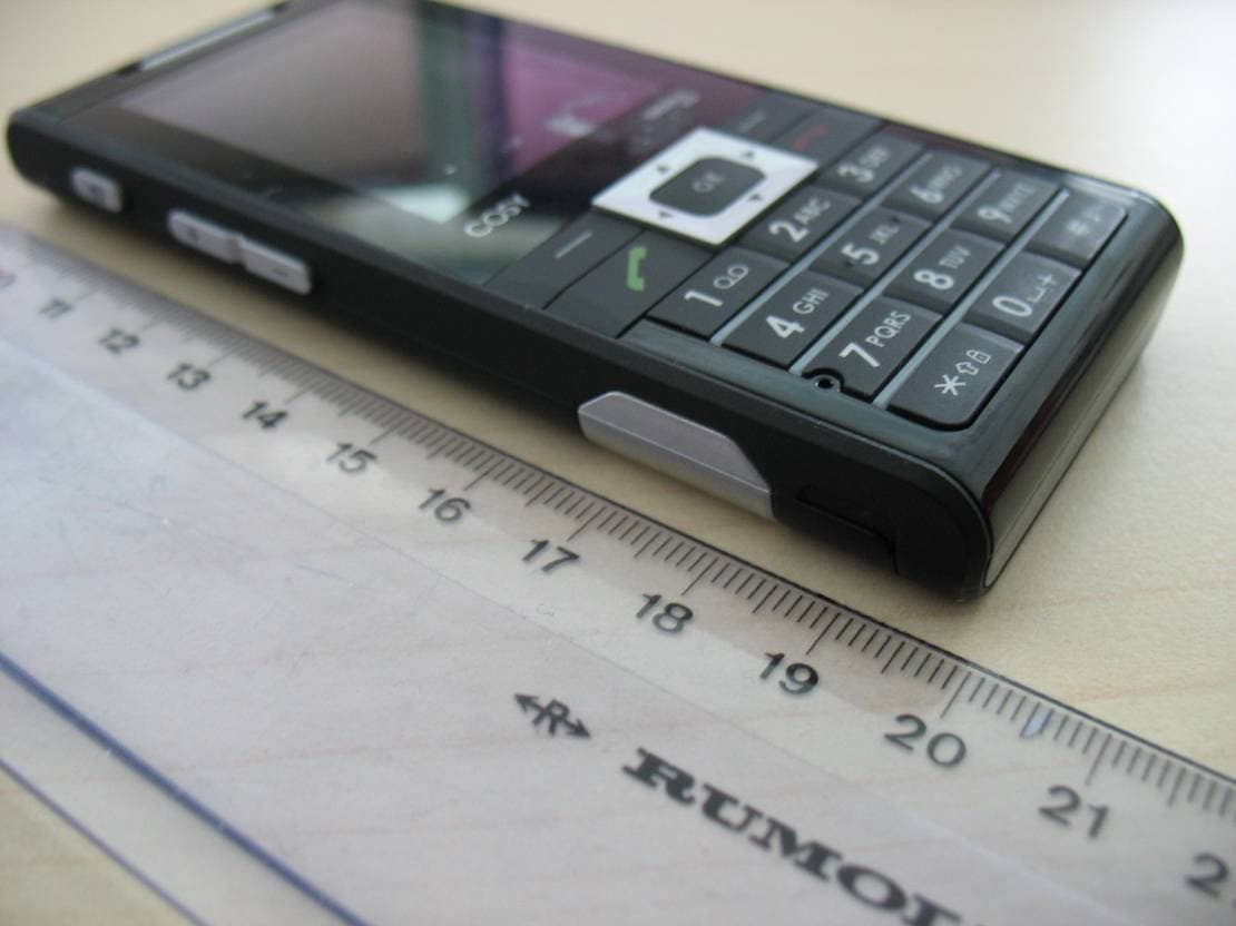
M9HCOSY3G
Oct 13, 2010COSY Phone 3G
Equipment Class
DXX - Part 15 Low Power Communication Device Transmitter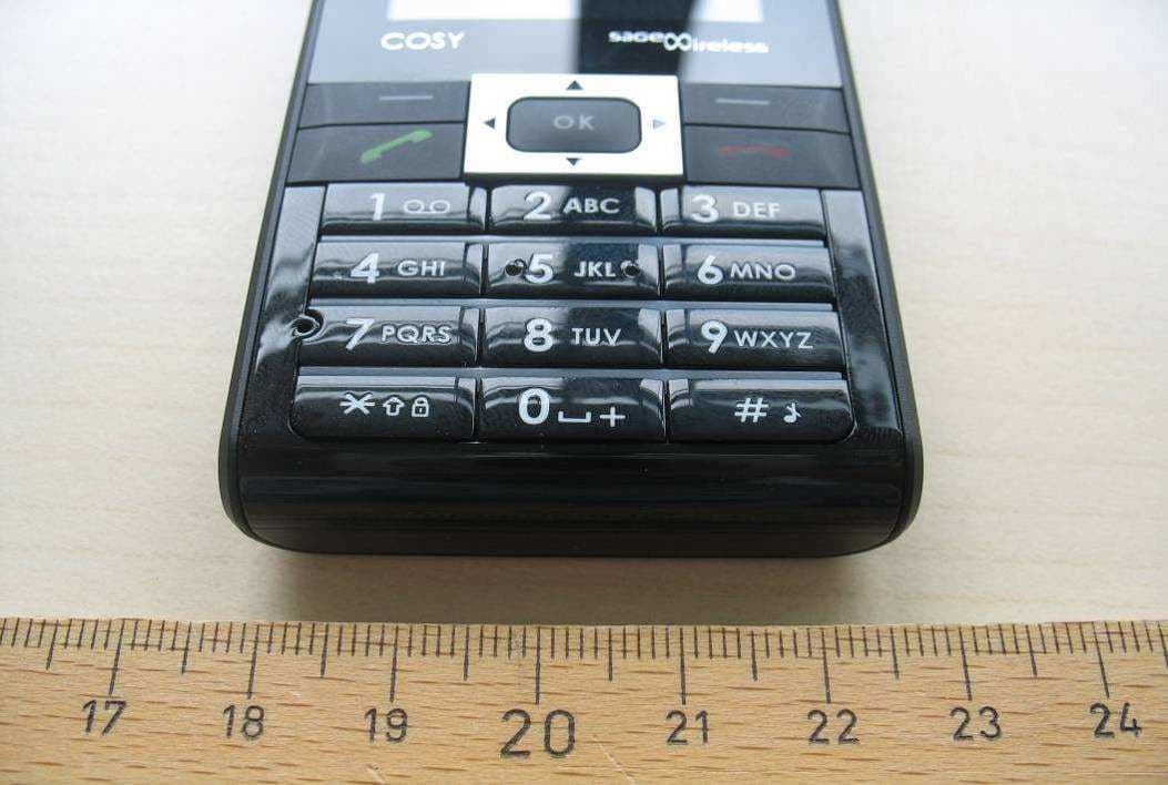
M9HCOSY2G
Sep 06, 2010COSY Phone 2G
Equipment Class
PCE - PCS Licensed Transmitter held to ear
M9HMOV001
Aug 18, 2010Handheld Top Up Terminal
Equipment Class
PCT - PCS Licensed Transmitter worn on body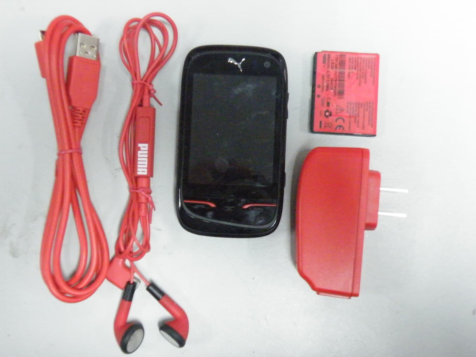
M9HPM1
Apr 26, 2010Mobile phone
Equipment Class
PCE - PCS Licensed Transmitter held to ear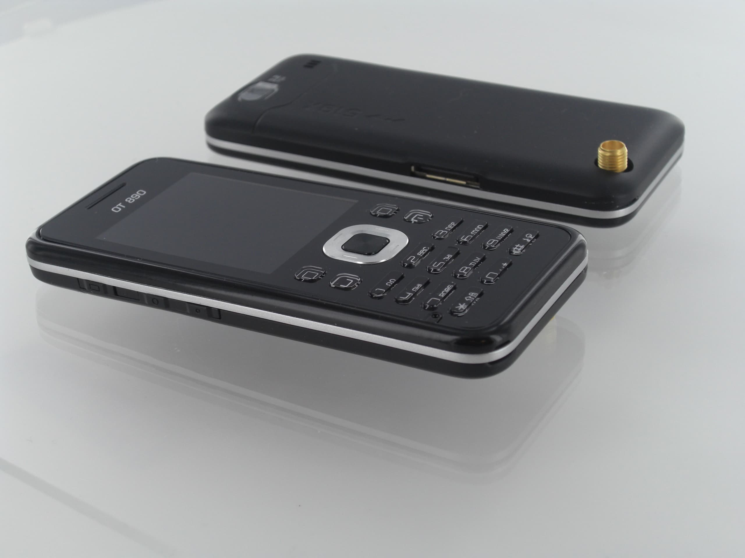
M9HOT8X0RF
Jan 31, 2010Network Measurement Device
Equipment Class
JBP - Part 15 Class B Computing Device Peripheral