M9HA2005WR3GSM 850/1900 Mobile Phone
Sagem Wireless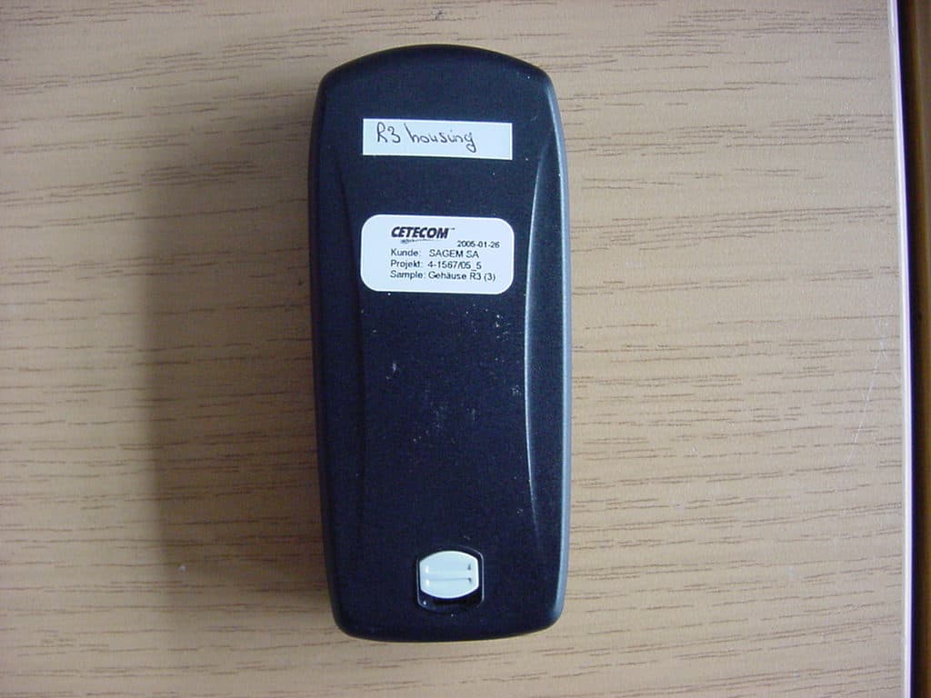
Click to zoom
Application Details
- Equipment Class
- PCE - PCS Licensed Transmitter held to ear
- Date of Grant
- Mar 14, 2005
- Application Purpose
- Original Equipment
- Date of Application
- Mar 14, 2005
- Equipment Note
- GSM 850/1900 Mobile Phone
- Frequency Range
- 824.20000000 - 848.80000000
- Company
- Sagem Wireless
- Country
- France
Documents & Files
Document Text
Text extracted from the exhibit documents filed with the FCC. Open a document above to read the original.
Users Manual
Mobile Phones Division www.sagem.com/mobiles Le Ponant de Paris - 27, rue Leblanc - 75512 PARIS CEDEX 15 - FRANCE SAGEM SA - Société anonyme à directoire et conseil de surveillance capital : 35 500 000 € - 562 082 909 RCS PARIS SAGEMSA myX-1_twin_courte.qxd 21/12/2004 9:55 Page 1 1 You have just bought a mobile phone and we congratulate you on your choice.Your phone will allow you to use different international networks (GSM 850 MHz and PCS 1900 MHz) depending on the roaming agreements between the operators. We would like to remind you that this phone is approved to European standards.To get the most out of using your phone, we recommend that you read this manual carefully and keep it handy for future reference if needed.WARNINGAccording to the configuration of t he networks and associated subscriptions, certain functions may not be available (usually indicated by *).Make sure your SIM card is compatible with your phone. If an incompatible SIM card is inserted, a message will be displayed when switching on your phone. For further information, contact your Operator.The SAGEM logo and trademark are the property of SAGEM SA.AT is a registered trademark of Hayes Microcomputer products Inc.Hayes is a registered trademark of Hayes Microcomputer Products Inc.T9™ Text Input is a registered trademark of ©Tegic Communications Inc.T9 is licensed under one or more of the following U.S. Patents: 5,818,437, 5,953,541, 5,187,480, 5,945,928, 6,011,554 and additional patents are pending worldwide. Compatibility of your SIM cardYour phone is compatible with SIM 3V cards only. 251873962_myX-1a Twin_lu_en.book Page 1 Vendredi, 7. janvier 2005 3:00 15 2Conformance Document SAGEM SA declare under its sole responsibility that the product Dual Band GSM/PCS Type A2005 conforms to the requirements of the following EEC directives:EEC Directive 1999/5/CE Safety EN 60950: 2001 Low voltage directive 73/23/CEE Network 3G PP TS 51.010- 1 TBR 19 Edition 5TBR 20 Edition 3EN 301511 v7.0.1 Health EN 50360 EN 50361 FCC Conformance DocumentFCC Part 24Network NAPRD03 v3.1.2 Health IEEE P1528/D1.2 251873962_myX-1a Twin_lu_en.book Page 2 Vendredi, 7. janvier 2005 3:00 15 3 Safety Information for Wi reless handled phones Use of your phone is subject to safety rules designed to protect the user and his or her environment.- Your wireless handheld portable phone is a low power radio transmitter and receiver. When it is ON, it receives and also sends out frequency (RF) signals. - In August, 1996, the Federal Communications Commissions (FCC) adopted RF exposure guidelines with safety levels for handheld wireless phones. Those guidelines are consistent with the safety standards previously set by both U.S. and international standards bodies: ANSI C95.1 (1992) (*) NCPR Report 86 (1986) (*) ICNIRP (1996) (*) - Those standards were based on comprehensive and periodic evaluations of the relevant scientific literature. For example, over 120 scientists, engineers, and physicians from universities, government health agencies, and industry reviewed the available body of research to develop the ANSI Standard (C95.1). - The design of your phone complies with the FCC guidelines (and those standards). - For body worn operation, this phone has been tested and meets FCC RF exposure guidelines when used with an accessory that contains no metal and that positions the handset a minimum of 1.5 cm from the body. Use of other accessories may not ensure compliance with FCC RF exposure guidelines. Exposure to Radio Frequency Signals (*) American National Standards Institute; National Council on Radiation Protection and Measurements; International Commission and Non-Ionizing Radiation Protection. 251873962_myX-1a Twin_lu_en.book Page 3 Vendredi, 7. janvier 2005 3:00 15 4Safety Information for Wi reless handled phones - Normal position: hold the phone as you would any other phone with the upper zone (back of the LCD display) pointed up and over your shoulder. - Tips on efficient operation: for your phone to operate most efficiently: do not touch cover unnecessarily the top part of the phone with your hand. This would cover the integrated antenna and affect call quality and may cause the phone to operate at a higher power level than otherwise needed. - Check the laws and regulations on the use of wireless telephones in the areas where you drive. Always obey them. Also, if using your phone while driving while driving please:• Give full attention of driving, driving safely is your first responsibility• Use hands-free operation, if available• Pull off the road and park before making or answering a call if driving conditions so require. - Most modern electronic equipment is shielded from RF signals. However, certain electronic equipment may not be shielded against the RF signals from your wireless phone. - Some phone accessories allow to reduce the radiation interferences of the phone. Please contact your distributor. Pacemakers The Health Industry Manufacturers Association recommends that a minimum separation of six (6”) inches be maintained between a handheld wireless phone and a pacemaker to avoid potential interference with the pacemaker. These recommendations are consistent with the independent research by and recommendations of Wireless Technology Research. Phone OperationDrivingElectronic Devices 251873962_myX-1a Twin_lu_en.book Page 4 Vendredi, 7. janvier 2005 3:00 15 5 Safety Information for Wi reless handled phones Persons with pacemakers:- Should ALWAYS keep the phone more than six inches from their pacemaker when the phone is turned ON - Should not carry the phone in the breast pocket- Should use the ear opposite to the pacemaker to minimize the potential for interference - If you have any reason to suspect that interference is taking place, turn your phone OFF immediately. Hearing Aids Some digital wireless phones may interfere with some hearing aids. In the event of such interference, you may want to consult your service provider. Other Medical Devic…
Text truncated - open the document above for the full version.
External Photos
CETECOM ICT Services GmbH Untertürkheimer Str. 6-10, 66117 Saarbruecken Phone: +49 (0) 681 598-0 Fax: -9075 RSC-Laboratory Phone: +49 (0) 681 598-0 Fax: -9075 Annex to Test report no.: 4-1567-05-04/05 Date: 2005-01-28 Page 55 of 56 8 Annex C: External Photographs of the Equipment Photo 1: CETECOM ICT Services GmbH Untertürkheimer Str. 6-10, 66117 Saarbruecken Phone: +49 (0) 681 598-0 Fax: -9075 RSC-Laboratory Phone: +49 (0) 681 598-0 Fax: -9075 Annex to Test report no.: 4-1567-05-04/05 Date: 2005-01-28 Page 56 of 56 Photo 2:
ID Label/Location Info
Sagem SA Centre de Saint Christophe - DTM TELEPHONIE MOBILE MOBILE PHONES Date : 16/02/05 Document SAGEM SA Reproduction et divulgation interdites 21/31 2.1.5 Label Informations Sagem SA Centre de Saint Christophe - DTM TELEPHONIE MOBILE MOBILE PHONES Date : 16/02/05 Document SAGEM SA Reproduction et divulgation interdites 22/31
Internal Photos
CETECOM ICT Services GmbH Untertürkheimer Str. 6-10, 66117 Saarbruecken Phone: +49 (0) 681 598-0 Fax: -9075 RSC-Laboratory Phone: +49 (0) 681 598-0 Fax: -9075 Annex to Test report no.: 4-1462-17-04/04 Date: 2004-11-26 Page 23 of 29 7 Annex D: Internal Photographs of the Equipment Photo 1: CETECOM ICT Services GmbH Untertürkheimer Str. 6-10, 66117 Saarbruecken Phone: +49 (0) 681 598-0 Fax: -9075 RSC-Laboratory Phone: +49 (0) 681 598-0 Fax: -9075 Annex to Test report no.: 4-1462-17-04/04 Date: 2004-11-26 Page 24 of 29 Photo 2: CETECOM ICT Services GmbH Untertürkheimer Str. 6-10, 66117 Saarbruecken Phone: +49 (0) 681 598-0 Fax: -9075 RSC-Laboratory Phone: +49 (0) 681 598-0 Fax: -9075 Annex to Test report no.: 4-1462-17-04/04 Date: 2004-11-26 Page 25 of 29 Photo 3: CETECOM ICT Services GmbH Untertürkheimer Str. 6-10, 66117 Saarbruecken Phone: +49 (0) 681 598-0 Fax: -9075 RSC-Laboratory Phone: +49 (0) 681 598-0 Fax: -9075 Annex to Test report no.: 4-1462-17-04/04 Date: 2004-11-26 Page 26 of 29 Photo 4: CETECOM ICT Services GmbH Untertürkheimer Str. 6-10, 66117 Saarbruecken Phone: +49 (0) 681 598-0 Fax: -9075 RSC-Laboratory Phone: +49 (0) 681 598-0 Fax: -9075 Annex to Test report no.: 4-1462-17-04/04 Date: 2004-11-26 Page 27 of 29 Photo 5: CETECOM ICT Services GmbH Untertürkheimer Str. 6-10, 66117 Saarbruecken Phone: +49 (0) 681 598-0 Fax: -9075 RSC-Laboratory Phone: +49 (0) 681 598-0 Fax: -9075 Annex to Test report no.: 4-1462-17-04/04 Date: 2004-11-26 Page 28 of 29 Photo 6: CETECOM ICT Services GmbH Untertürkheimer Str. 6-10, 66117 Saarbruecken Phone: +49 (0) 681 598-0 Fax: -9075 RSC-Laboratory Phone: +49 (0) 681 598-0 Fax: -9075 Annex to Test report no.: 4-1462-17-04/04 Date: 2004-11-26 Page 29 of 29 Photo 7:
RF Exposure Info
CETECOM ICT Services GmbH Untertuerkheimer Str. 6-10, 66117 Saarbruecken, Germany Phone: +49 (0) 681 598-0 Fax: -8475 SAR-Laboratory Phone: +49 (0) 681 598-8454 . As of 2005-02-04 Page 1 of 38 Accredited testing laboratory DAR registration number: TTI-P-G 166/98 Federal Motor Transport Authority (KBA) DAR registration number: KBA-P 00070-97 Appendix to test report 4-1567-05-02/05 Calibration data, Phantom certificate and detail information of the DASY4 System CETECOM ICT Services GmbH Calibration Data and Phantom Information to test report no.: 4-1567-05-02/05 As of 2005-02-04 Page 2 of 38 Table of Content 1 Calibration report “Probe ET3DV6” .................................................................................................................................... 3 2 Calibration report “900 MHz System validation dipole” .................................................................................................. 11 3 Calibration report “1900 MHz System validation dipole .................................................................................................. 21 4 Calibration certificate of Data Aquisition Unit (DAE) ...................................................................................................... 30 5 Certificate of “SAM Twin Phantom V4.0/V4.0C” ........................................................................................................... 31 6 Application Note System Performance Check ................................................................................................................... 33 2005-02-04 CETECOM ICT Services GmbH Calibration Data and Phantom Information to test report no.: 4-1567-05-02/05 As of 2005-02-04 Page 3 of 38 1 Calibration report “Probe ET3DV6” CETECOM ICT Services GmbH Calibration Data and Phantom Information to test report no.: 4-1567-05-02/05 As of 2005-02-04 Page 4 of 38 CETECOM ICT Services GmbH Calibration Data and Phantom Information to test report no.: 4-1567-05-02/05 As of 2005-02-04 Page 5 of 38 CETECOM ICT Services GmbH Calibration Data and Phantom Information to test report no.: 4-1567-05-02/05 As of 2005-02-04 Page 6 of 38 CETECOM ICT Services GmbH Calibration Data and Phantom Information to test report no.: 4-1567-05-02/05 As of 2005-02-04 Page 7 of 38 CETECOM ICT Services GmbH Calibration Data and Phantom Information to test report no.: 4-1567-05-02/05 As of 2005-02-04 Page 8 of 38 CETECOM ICT Services GmbH Calibration Data and Phantom Information to test report no.: 4-1567-05-02/05 As of 2005-02-04 Page 9 of 38 CETECOM ICT Services GmbH Calibration Data and Phantom Information to test report no.: 4-1567-05-02/05 As of 2005-02-04 Page 10 of 38 CETECOM ICT Services GmbH Calibration Data and Phantom Information to test report no.: 4-1567-05-02/05 As of 2005-02-04 Page 11 of 38 2 Calibration report “900 MHz System validation dipole” CETECOM ICT Services GmbH Calibration Data and Phantom Information to test report no.: 4-1567-05-02/05 As of 2005-02-04 Page 12 of 38 CETECOM ICT Services GmbH Calibration Data and Phantom Information to test report no.: 4-1567-05-02/05 As of 2005-02-04 Page 13 of 38 CETECOM ICT Services GmbH Calibration Data and Phantom Information to test report no.: 4-1567-05-02/05 As of 2005-02-04 Page 14 of 38 CETECOM ICT Services GmbH Calibration Data and Phantom Information to test report no.: 4-1567-05-02/05 As of 2005-02-04 Page 15 of 38 CETECOM ICT Services GmbH Calibration Data and Phantom Information to test report no.: 4-1567-05-02/05 As of 2005-02-04 Page 16 of 38 CETECOM ICT Services GmbH Calibration Data and Phantom Information to test report no.: 4-1567-05-02/05 As of 2005-02-04 Page 17 of 38 CETECOM ICT Services GmbH Calibration Data and Phantom Information to test report no.: 4-1567-05-02/05 As of 2005-02-04 Page 18 of 38 CETECOM ICT Services GmbH Calibration Data and Phantom Information to test report no.: 4-1567-05-02/05 As of 2005-02-04 Page 19 of 38 CETECOM ICT Services GmbH Calibration Data and Phantom Information to test report no.: 4-1567-05-02/05 As of 2005-02-04 Page 20 of 38
RF Exposure Info
CETECOM ICT Services GmbH Calibration Data and Phantom Information to test report no.: 4-1567-05-02/05 As of 2005-02-04 Page 21 of 38 3 Calibration report “1900 MHz System validation dipole CETECOM ICT Services GmbH Calibration Data and Phantom Information to test report no.: 4-1567-05-02/05 As of 2005-02-04 Page 22 of 38 CETECOM ICT Services GmbH Calibration Data and Phantom Information to test report no.: 4-1567-05-02/05 As of 2005-02-04 Page 23 of 38 CETECOM ICT Services GmbH Calibration Data and Phantom Information to test report no.: 4-1567-05-02/05 As of 2005-02-04 Page 24 of 38 CETECOM ICT Services GmbH Calibration Data and Phantom Information to test report no.: 4-1567-05-02/05 As of 2005-02-04 Page 25 of 38 CETECOM ICT Services GmbH Calibration Data and Phantom Information to test report no.: 4-1567-05-02/05 As of 2005-02-04 Page 26 of 38 CETECOM ICT Services GmbH Calibration Data and Phantom Information to test report no.: 4-1567-05-02/05 As of 2005-02-04 Page 27 of 38 CETECOM ICT Services GmbH Calibration Data and Phantom Information to test report no.: 4-1567-05-02/05 As of 2005-02-04 Page 28 of 38 CETECOM ICT Services GmbH Calibration Data and Phantom Information to test report no.: 4-1567-05-02/05 As of 2005-02-04 Page 29 of 38 CETECOM ICT Services GmbH Calibration Data and Phantom Information to test report no.: 4-1567-05-02/05 As of 2005-02-04 Page 30 of 38 4 Calibration certificate of Data Aquisition Unit (DAE) CETECOM ICT Services GmbH Calibration Data and Phantom Information to test report no.: 4-1567-05-02/05 As of 2005-02-04 Page 31 of 38 5 Certificate of “SAM Twin Phantom V4.0/V4.0C” CETECOM ICT Services GmbH Calibration Data and Phantom Information to test report no.: 4-1567-05-02/05 As of 2005-02-04 Page 32 of 38 CETECOM ICT Services GmbH Calibration Data and Phantom Information to test report no.: 4-1567-05-02/05 As of 2005-02-04 Page 33 of 38 6 Application Note System Performance Check 6.1.1.1 Purpose of system performance check The system performance check verifies that the system operates within its specifica-tions. System and operator errors can be detected and corrected. It is recommended that the system performance check is performed prior to any usage of the system in order to guarantee reproducible results. The measurement of the Specific Absorption Rate (SAR) is a complicated task and the result depends on the proper functioning of many components and the correct settings of many param-eters. Faulty results due to drift, failures or incorrect parameters might not be recognized, since they often look similar in distribution to the correct ones. The Dosimetric Assessment System DASY4 incorporates a system performance check procedure to test the proper functioning of the system. The system performance check uses normal SAR measurements in a simplified setup (the at section of the SAM Twin Phantom) with a well characterized source (a matched dipole at a specified distance). This setup was selected to give a high sensitivity to all parameters that might fail or vary over time (e.g., probe, liquid parameters, and software settings) and a low sensitivity to external effects inherent in the system (e.g., positioning uncertainty of the device holder). The system performance check does not replace the calibration of the components. The accuracy of the system performance check is not sufficient for calibration purposes. It is possible to calculate the field quite accurately in this simple setup; however, due to the open field situation some factors (e.g., laboratory re ections) cannot be accounted for. Calibrations in the at phantom are possible with transfer calibration methods, using either temperature probes or calibrated E-field probes. The system performance check also does not test the system performance for arbitrary field sit-uations encountered during real measurements of mobile phones. These checks are performed at SPEAG by testing the components under various conditions (e.g., spherical isotropy measurements in liquid, linearity measurements, temperature variations, etc.), the results of which are used for an error estimation of the system. The system performance check will indicate situations where the system uncertainty is exceeded due to drift or failure. 6.1.1.2 System Performance check procedure Preparation The conductivity should be measured before the validation and the measured liquid parameters must be entered in the software. If the measured values differ from targeted values in the dipole document, the liquid composition should be adjusted. If the validation is performed with slightly different (measured) liquid parameters, the expected SAR will also be different. See the application note about SAR sensitivities for an estimate of possible SAR deviations. Note that the liquid parameters are temperature dependent with approximately – 0.5% decrease in permitivity and + 1% increase in conductivity for a temperature decrease of 1° C. The dipole must be placed beneath the flat phantom section of the Generic Twin Phantom with the correct distance holder in place. The distance holder should touch the phantom surface with a light pressure at the reference marking (little hole) and be oriented parallel to the long side of the phantom. Accurate positioning is not necessary, since the system will search for the peak SAR location, except that the dipole arms should be parallel to the surface. The device holder for mobile phones can be left in place but should be rotated away from the dipole. The forward power into the dipole at the dipole SMA connector should be determined as accurately as possible. See section 4 for a description of the recommended setup to measure the dipole input power. The actual dipole input power level can be between 20mW and several watts. The result can later be normalized to any power level. It is strongly recommended to note the actually used power level in the „comment“-window of the measurement file; otherwise you loose this c…
Text truncated - open the document above for the full version.
RF Exposure Info
CETECOM ICT Services GmbH Untertuerkheimer Str. 6-10, 66117 Saarbruecken, Germany Phone: +49 (0) 681 598-0 Fax: -8475 SAR-Laboratory Phone: +49 (0) 681 598-8454 . As of 2005-02-04 Page 1 of 68 Accredited testing laboratory DAR registration number: TTI-P-G 081/94-D0 Federal Motor Transport Authority (KBA) DAR registration number: KBA-P 00070-97 Test report no. : 4-1567-05-02/05 Type identification : A2005a+ (Design R3) Test specification : IEEE P1528/D1.2 FCC-ID : M9HA2005WR3 Test specification : CETECOM ICT Services GmbH Test report no.: 4-1567-05-02/05 As of 2005-02-04 Page 2 of 68 Table of Contents 1 General Information............................................................................................................................................................... 3 1.1 Notes ............................................................................................................................................................................... 3 1.1.1 Statement of Compliance ....................................................................................................................................... 3 1.2 Testing laboratory............................................................................................................................................................ 4 1.3 Details of applicant.......................................................................................................................................................... 4 1.4 Application details........................................................................................................................................................... 4 1.5 Test item .......................................................................................................................................................................... 5 1.6 Test specification(s) ........................................................................................................................................................ 6 1.6.1 RF exposure limits ................................................................................................................................................. 6 2 Technical test ......................................................................................................................................................................... 7 2.1 Summary of test results ................................................................................................................................................... 7 2.2 Test environment ............................................................................................................................................................. 7 2.3 Measurement and test set-up ........................................................................................................................................... 7 2.4 Measurement system ....................................................................................................................................................... 8 2.4.1 System Description ................................................................................................................................................ 8 2.4.2 Test environment ................................................................................................................................................... 9 2.4.3 Probe description ................................................................................................................................................... 9 2.4.4 Phantom description ............................................................................................................................................ 10 2.4.5 Device holder description .................................................................................................................................... 10 2.4.6 Scanning procedure.............................................................................................................................................. 11 2.4.7 Spatial Peak SAR Evaluation............................................................................................................................... 12 2.4.8 Data Storage and Evaluation................................................................................................................................ 13 2.4.9 Test equipment utilized........................................................................................................................................ 15 2.4.10 Tissue simulating liquids : dielectric properties................................................................................................... 16 2.4.11 Tissue simulating liquids : parameters................................................................................................................. 17 2.4.12 Measurement uncertainty evaluation for SAR test .............................................................................................. 18 2.4.13 Measurement uncertainty evaluation for system validation................................................................................. 19 2.4.14 System validation................................................................................................................................................. 20 2.4.15 Validation procedure............................................................................................................................................ 21 2.5 Test results (Head and Body SAR)................................................................................................................................ 22 2.5.1 Description of test procedures ............................................................................................................................. 23 2.6 Test results (conducted power measurement…
Text truncated - open the document above for the full version.
Test Report
CETECOM ICT Services GmbH Untertürkheimer Str. 6-10, 66117 Saarbruecken Phone: +49 (0) 681 598-0 Fax: -9075 RSC-Laboratory Phone: +49 (0) 681 598-0 Fax: -9075 Test report no.: 4-1567-05-04/05 Date: 2005-01-28 Page 1 of 79 Recognized by the Federal Communications Commission Anechoic chamber registration no.: 90462 (FCC) Anechoic chamber registration no.: 3463 (IC) TCB ID: DE 0001 Accredited by the German Accreditation Council DAR–Registration Number TTI–P–G 081/94-D0 Independent ETSI compliance test house ETSI Accredited Bluetooth ® Test Facility (BQTF) Test report no. : 4-1567-05-04/05 Applicant : Sagem SA Type : A2005a+ (Design R3) Test Standard : FCC Part 22, 24 RSS132, 133 FCC ID : M9HA2005WR3 Certification No. IC : --- CETECOM ICT Services GmbH Untertürkheimer Str. 6-10, 66117 Saarbruecken Phone: +49 (0) 681 598-0 Fax: -9075 RSC-Laboratory Phone: +49 (0) 681 598-0 Fax: -9075 Test report no.: 4-1567-05-04/05 Date: 2005-01-28 Page 2 of 79 Table of contents 1 GENERAL INFORMATION ................................................................................................................................... 3 1.1. ADMINISTRATIVE DATA OF THE TEST FACILITY..................................................................................................... 3 1.1.1 Identification of the testing laboratory ......................................................................................................... 3 1.2. NOTES................................................................................................................................................................... 3 1.3 DETAILS OF APPLICANT......................................................................................................................................... 4 1.4 APPLICATION DETAILS.......................................................................................................................................... 4 1.5 TEST ITEM............................................................................................................................................................. 5 1.6 TEST SETUP........................................................................................................................................................... 6 1.7 TEST STANDARDS.................................................................................................................................................. 6 2 STATEMENT OF COMPLIANCE .......................................................................................................................... 7 2.1 SUMMARY OF MEASUREMENT RESULTS................................................................................................................ 7 2.1.1 PCS 1900 ...................................................................................................................................................... 7 2.1.2 GSM 850 ....................................................................................................................................................... 7 3 MEASUREMENTS AND RESULTS ....................................................................................................................... 8 3.1 PART PCS 1900 ................................................................................................................................................... 8 3.1.1 RF Power Output .......................................................................................................................................... 8 3.1.2 Frequency Stability..................................................................................................................................... 12 3.1.3 Radiated Emissions..................................................................................................................................... 15 3.1.4 Receiver Radiated Emissions ...................................................................................................................... 25 3.1.6 Block Edge Compliance .............................................................................................................................. 33 3.1.7 Occupied Bandwidth................................................................................................................................... 36 3.2 PART GSM 850 ................................................................................................................................................. 43 3.2.1 RF Power Output ........................................................................................................................................ 43 3.2.2 Frequency Stability..................................................................................................................................... 46 3.2.3 Radiated Emissions..................................................................................................................................... 49 3.2.4 Receiver Radiated Emissions ...................................................................................................................... 59 3.2.5 Conducted Spurious Emissions ...............................................................................................................…
Text truncated - open the document above for the full version.
Contact Information
Applicant
Francois CHAMBON(GM)
Test Firm
Cetecom ICT Services GmbHRalf Hoehn
Technical Specifications
| # | Rule Parts | Frequency Range | Power Output | Emission | Tolerance |
|---|---|---|---|---|---|
| 2 | 22H | 824.2 MHz - 848.8 MHz | 955.00 mW | 300KGXW | 0.0282 ppm |
Other Applications from Sagem Wireless
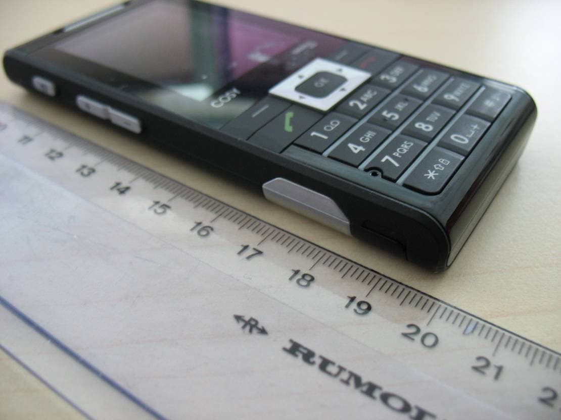
M9HCOSY3G
Oct 13, 2010COSY Phone 3G
Equipment Class
DXX - Part 15 Low Power Communication Device Transmitter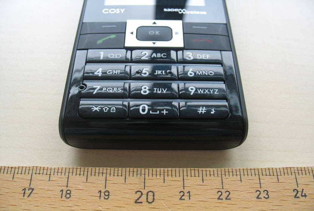
M9HCOSY2G
Sep 06, 2010COSY Phone 2G
Equipment Class
PCE - PCS Licensed Transmitter held to ear
M9HMOV001
Aug 18, 2010Handheld Top Up Terminal
Equipment Class
PCT - PCS Licensed Transmitter worn on body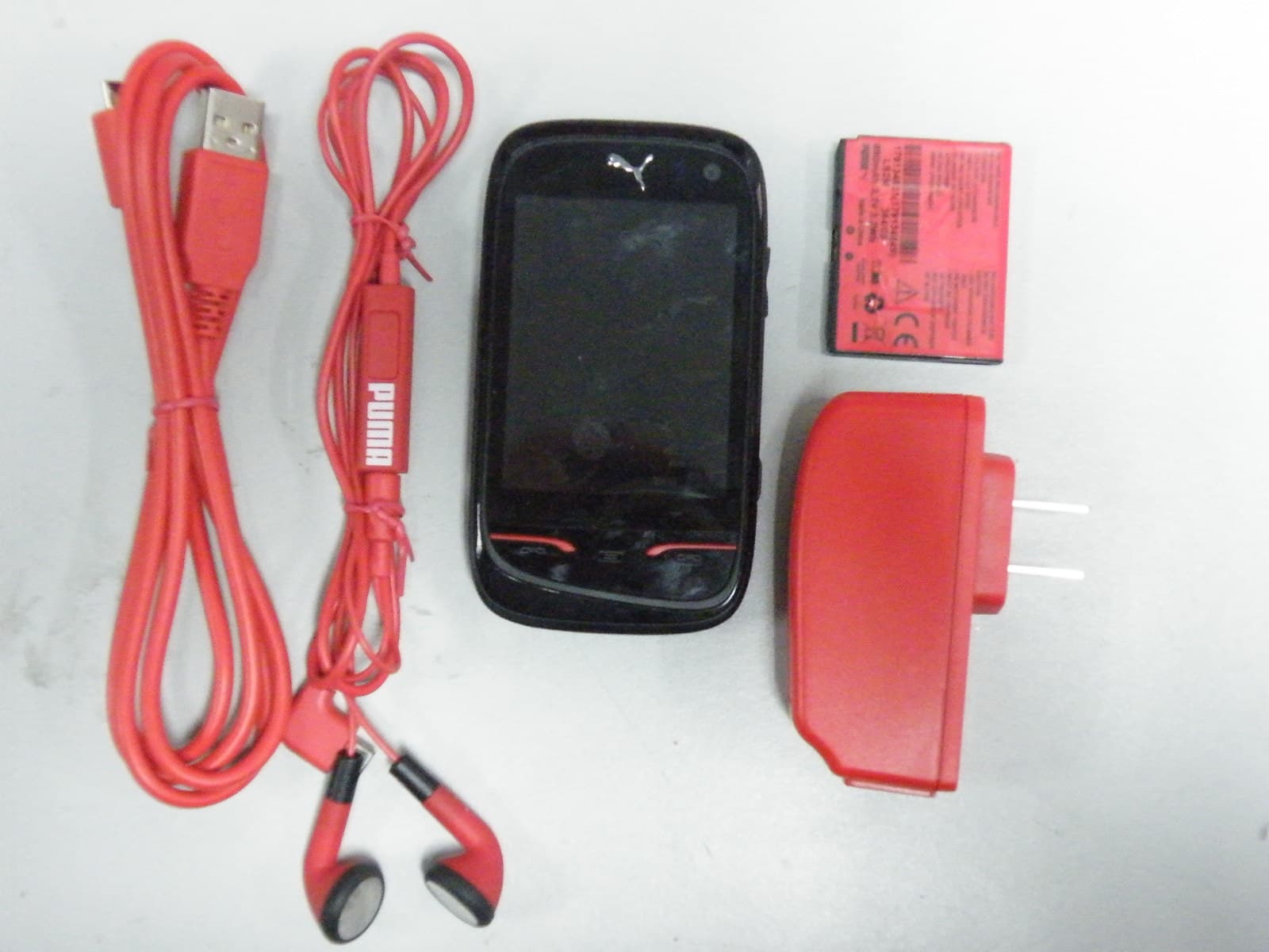
M9HPM1
Apr 26, 2010Mobile phone
Equipment Class
PCE - PCS Licensed Transmitter held to ear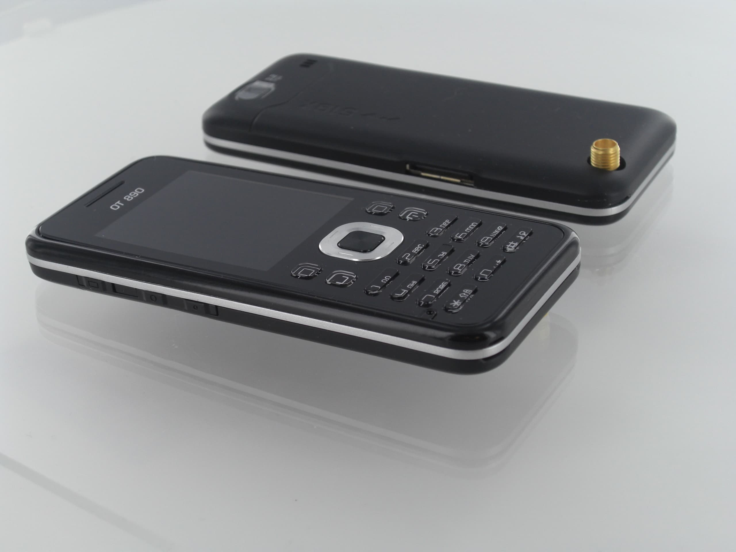
M9HOT8X0RF
Jan 31, 2010Network Measurement Device
Equipment Class
JBP - Part 15 Class B Computing Device Peripheral