MAU016A770 Notebook Computer with Wireless LAN
Getac Technology Corp.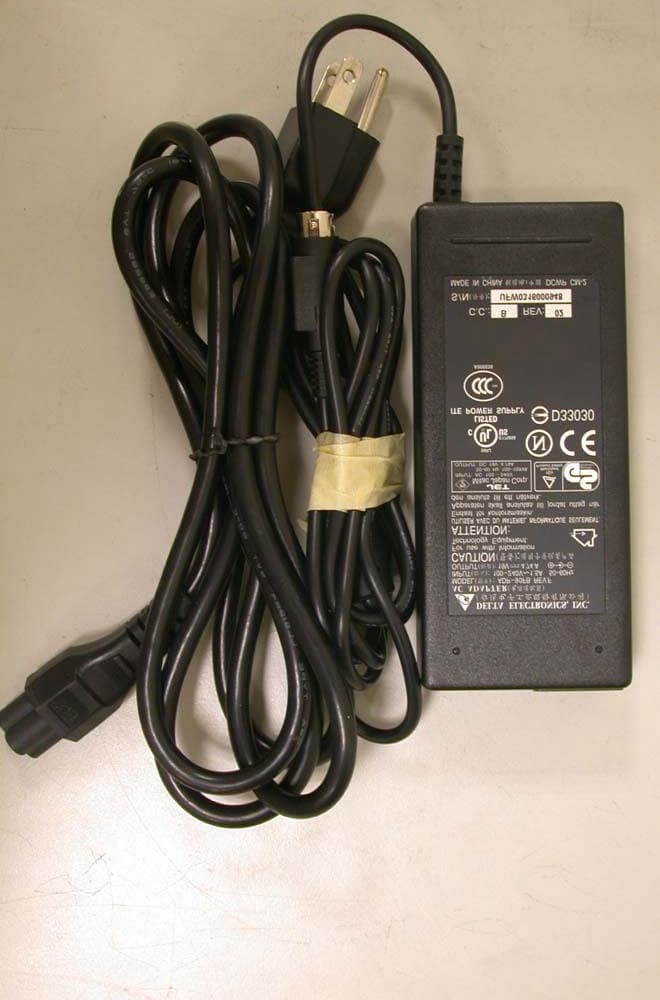
Click to zoom
Application Details
- Equipment Class
- DTS - Digital Transmission System
- Date of Grant
- Feb 06, 2005
- Application Purpose
- Original Equipment
- Date of Application
- Feb 06, 2005
- Equipment Note
- A770 Notebook Computer with Wireless LAN
- Frequency Range
- 2412.00000000 - 2462.00000000
- Company
- Getac Technology Corp.
- Country
- Taiwan
Documents & Files
Document Text
Text extracted from the exhibit documents filed with the FCC. Open a document above to read the original.
Users Manual
A770 ENHANCE SERIES NOTEBOOK OPERATOR’S MANUAL MITAC Technology Corporation P/N: 799001180012 R00 a © Copyright by MTC Corporation 1998. All rights reserved. No part of this publication maybe reproduced by any means for any reason without express written approval from MTC Corporation or its authorized representative. MTC Corporation makes no representations, either express or implied concerning the accuracy of this manual. All the information contained herein is believed to be complete and reliable as of the printing date. MTC Corporation reserves the right to make changes to this manual or product specifications without obligation to notify any person of such changes. IBM, IBM PC/AT and OS/2 are registered trademarks of International Business Machines Corporation. Intel Pentium is a registered trademark of Intel Corporation. MS-DOS, Windows 2000/Windows XP are registered trademarks of Microsoft Corporation. UNIX is a registered trademark of AT&T Bell Laboratories. Other brand and product names are trademarks and/or registered trademarks of their respective holders. b Class B Regulations Federal Communications Commission Radio Frequency Interference Statement NOTE: This equipment has been tested and found to comply with the limits for a Class B digital device pursuant to Part 15 of the FCC Rules. These limits are design to provide reasonable protection against harmful interference in a residential installation. This equipment generates, uses, and can radiate radio frequency energy and, if not installed and used in accordance with the instructions, may cause harmful interference to radio communications. However, there is no guarantee that interference will not occur in a particular installation. If this equipment does cause harmful interference to radio or television reception, which can be determined by turning the equipment off and on, the user is encouraged to try to correct the interference by one or more of the following measures: Reorient or relocate the receiving antenna. Increase the separation between the equipment and receiver. Connect the equipment into an outlet on a circuit different from that to which the receiver is connected. Consult the dealer or an experienced radio/TV technician for help. Any changes or modifications not expressly approved by the manufacturer could void the user’s authority to operate the equipment. Please note: 1. The use of a non-shielded interface cable with this equipment is prohibited. 2. A shielded AC power cord must be used with this equipment. c WARNING To assure continued compliance, use only shielded interface cables when connecting to a computer or peripheral. Also, any change or modifications not expressly appoved by the party responsible for complience could void the user’s authority to operate this equipment. FCC RF Exposure Warning: This computer is provided with PC Card skit that could be used with wireless transmitter(s) , which will be specifically recommended, when they become available. Other third-party wireless transmitter(s) have not been RF exposure wvaluated for use with this computer and may not comply with FCC RF exposure requirements. This equipment complies with FCC radiation exposure limits set forth for an uncontrolled environement. This equipment must be installed and operated in accordance with provided instructions and minimum 20 cm spacing must be provided between antenna and all person’s body ( excluding extremities of hands, wrist and feet) during wireless modes of operation. This transmitter must not be co-located or operated in conjunction with any other antenna or transmitter. This device complies with Part 15 of the FCC Rrules. Operation is subject to the following two conditions: (1)This device may not cause harmful interface, and (2)This device must accept any interface received, including that may cause undesired operation. d Products with the CE Marking comply with both the EMC Directive (89/336/EEC) and the Low Voltage Directive (73/23/EEC) issued by the Commission of the European Community. Compliance with these directives implies conformity to the following European Norms: ? EN50081-1: Electromagnetic compatibility-Generic emmision standard ? EN55022: conducted Emission, Radiated Emission ? EN61000-3-2: Current Harmonic ? EN61000-3-3: Voltage Flicker ? EN50082-2: Electromagnetic compatibility-Generic immunity standard ? IEC1000-4-2: Electrostatic Discharge ? IEC1000-4-3: Radiated Susceptibility ? IEC1000-4-4: Electrical Fast Transients ? IEC1000-4-5: Surge Test ? IEC1000-4-6: Conducted Susceptibility ? IEC1000-4-11: Voltage Dip and Interruption e Record of Changes CHANGE NO. DATE TITLE OR BRIEF DESCRIPTION ENTERED BY 00 06, Oct.,2003 Initial Release 01 14, June, 2004 Add section 3-2.6 f Preface This is the A770 Series Notebook Operation Guide. Contents This manual contains information for personnel using the A770 Series notebook computer. Readers should have a basic understanding of Windows 2000 or Windows XP operating system installed on the computer when reading this document. With the exception of the SETUP configuration program, which is part of the system firmware, this manual does not explain any of the software or devices used with the system. Supplemental manuals or text-based documents on the hard disk supply information about any software included with the system. Audience All operators using the notebook in or out of the field should read and become familiar with this manual. Organization This manual has four chapters. Chapter 1 introduces the notebook pointing out its major features. Chapter 2 explains daily operation. Chapter 3 gives detailed information about configuring the notebook. Chapter 4 introduces the notebook Maintenance. Supplemental Reading For further information about this computer and computing in general, use these references: ? A770 Series Service Manual for detailed troubleshooting and repair instructions for serious hardware problems associated with the A770 Series notebook.…
Text truncated - open the document above for the full version.
Cover Letter(s)
Rev 2 C:\tmp\05LR002 A770\fcc\AP FORM.doc 02/08/02 American Telecommunications Certification Body, Inc. 6731 Whittier Avenue McLean, VA 22101 Ph: (703) 847-4700 FAX: (703) 847-6888 Certification Application Package AmericanTCB CERTIFICATION APPLICATION Rev 2 C:\tmp\05LR002 A770\fcc\AP FORM.doc 02/08/02 Mitac Technology Corp. 1st, R&D Road 2 , Hsinchu Science-Based Industrial Park, Hsinchu, Taiwan, R. O. C. This TESTING AND CERTIFICATION AGREEMENT ("Agreement") is made effective as of the latter date of execution below, by and between American Telecommunication Certification Body (ATCB) and Mitac Technology Corp.(Applicant), collectively referred to as "the Parties". Equipment Description Equipment Description: Notebook Personal Computer Model Number : A770 FCC Rule Part(s ): 15C In consideration of the mutual covenants in this Agreement, ATCB or its subcontractors will perform certification inspection services to determine if Applicant's device(s) identified above under Equipment Description (hereinafter "Devices") are in compliance with the laws, regulations and technical standards (hereinafter "Certification Regulations") of the national authorities specified by Applicant in Schedule A. 1. General 1.1 This Agreement is for the purpose of testing and certification and applies to all tests, audits, and certifications for the Devices, and will be performed in accordance with the Certification Regulations of the national authorities specified in Schedule A. 1.2 ATCB retains full discretion to determine if the Devices are compliant with the Certification Regulations of the Countries. In the event that certification is not issued for the aforementioned Devices, ATCB agrees to advise Applicant in writing of the reasons thereof. 1.3 This Agreement may not be assigned to or acquired by any other person, firm, or corporation without ATCB's written authorization. 2. Scope of Performance 2.1 The scope of performance between the Parties shall be agreed to by contract, purchase order or other mutually agreed-upon schedule or order. 2.2 Except as provided in Section 2.3 hereof, testing of all Devices shall take place at ATCB facilities. 2.3 In lieu of section 2.2 above, ATCB may agree to accept test data from any ISO/IEC Guide 25 accredited laboratory or FCC-Listed Laboratory and evaluate the Devices on the basis of this data. ATCB may also choose to accept test data from ISO Guide 25 accredited laboratories owned by Applicant, provided the requirements of 2.3.1. are met. 2.3.1 Employees of Applicant shall not participate in any tests, evaluations, or assessments described in sections 2.2 or 2.3 above without the presence and supervision of an ATCB engineer or technician. 2.4 If requested for sample purposes (as required by the FCC), client shall supply ATCB, at no charge, with at least one test sample of each Device, including the necessary peripherals, connecting cables, accessories or other hardware or software (hereinafter collectively referred to as "support equipment") required for testing, evaluation, and assessment. 2.5 Applicant shall supply ATCB, at no charge, with all technical documentation and materials required for the testing, evaluation, and assessment of such Devices and support equipment. 2.5.1 Technical documentation and materials include, but are not limited to, any relevant operating instructions, schematics, block diagrams, photographs, prior tests and certificates concerning the safety of the Devices, its components or support equipment. 2.6 Applicant recognizes that Device samples, including support equipment, may be damaged or completely destroyed when subjected to ATCB's testing and evaluation process. Applicant shall hold ATCB harmless for any such damage or destruction to its equipment. 2.7 If necessary ATCB shall test, evaluate, or assess Applicant's equipment within 30 business days of ATCB's receipt of such Devices, support equipment and technical documentation, and to work diligently until certification is granted or denied, or Applicant decides to abandon testing, evaluation, and assessment on such Devices. AmericanTCB CERTIFICATION APPLICATION Rev 2 C:\tmp\05LR002 A770\fcc\AP FORM.doc 02/08/02 2.8 Upon completion of testing, evaluation, or assessment, ATCB shall advise Applicant via an abbreviated report whether the results are favorable, and what, if any, conditions, limitations or qualifications to the requested Certification exist. 2.9 Applicant agrees that a full report is available to Applicant only by special request, and for the separate charge specified. 2.10 Where testing, evaluation, and assessment results in certification, ATCB shall certify Applicant's equipment as compliant with the laws, regulations and/or standards of the Countries within 30 business days from the date testing, evaluation, and assessment is completed. 2.10.1 Section 2.11 may be dependent upon a timely response by the United States Federal Communications Commission (FCC) or its foreign equivalent. 2.10.2 In the event of product certification, Applicant may request that ATCB return or destroy Applicant's Device sample(s), equipment support, and technical documentation. Applicant shall bear all costs associated with the return or destruction of such equipment test sample(s) and support equipment. 2.11 Where testing, evaluation, and assessment does not result in certification, ATCB shall provide cost-free storage for each Device sample, support equipment, and technical documentation for a period not to exceed 30 days, provided Applicant agrees to re-testing within this period when notified of the Device's failure. 2.12 If Applicant does not collect or accept receipt of the Device sample(s), support equipment and technical documentation, despite ATCB having sent notice pursuant to subsection 2.12.1, ATCB reserves the right to dispose of them at Applicant's expense. 2.13 Applicant shall retain all documents forwarded to it by ATCB as required by the Certification Regulations of the Countries…
Text truncated - open the document above for the full version.
Cover Letter(s)
Mitac Technology Corp. 1st, R&D Road 2 , Hsinchu Science-Based Industrial Park, Hsinchu, Taiwan, R.O.C. TEL : 886-3-5782280 FAX : 886-3-5778270 Letter Of Agency Date: Feb. 3rd, 2005 American Telecommunications Certification Body, Inc. 6731 Whittier Avenue Suite C110 McLean, VA 22101 RE: Certification Applications FCC ID: MAU016 Model: A770 To Whom It May Concern: Please be advised that Mitac Technology Corporation authorizes International Standards Laboratory (ISL) to act on our behalf, until otherwise notified, for applications submitted to American Telecommunications Certification Body, Inc. (ATCB). We certify that we are not subject to denial of federal benefits that includes FCC benefits, pursuant to Section 5301 of the Anti-Drug Abuse ACT of 1988, U.S.C. 862. Further, no party as defined in 47 CFR 1.2002(b), for this application is subject to denial of federal benefits that includes FCC benefits. Thank you for your attention to this matter. _______________________ Eric Pang / Engineer Mitac Technology Corp.
External Photos
EUT-1. EUT-2. EUT-3. EUT-4. EUT-5. EUT-6. EUT-7.
ID Label/Location Info
Label & Location Label
Internal Photos
EUT-1. EUT-2. EUT-3. EUT-4. EUT-5. EUT-6. EUT-7. EUT-8. EUT-9. EUT-10. EUT-11. EUT-12. EUT-13. EUT-14. EUT-15. EUT-16. EUT-17. EUT-18. EUT-19. EUT-20. EUT-21.
RF Exposure Info
Report Number: ISL-05LR002MPE Issue Date:2005/02/01 HC LAB:NVLAP:200234-0;VCCI: R-341,C-354;NEMKO:ELA 113a,113c;BSMI:SL2-IN-E-0037;SL2-R1-E-0037;CNLA:1178 LT LAB:NVLAP:200234-0;VCCI: R-1435,C-1440;NEMKO:ELA 113b,113d;BSMI:SL2-IN-E-0013;CNLA:0997 ISL-T10-R29-1 MPE Test Report of Product Name Notebook Personal Computer (with Intel PRO/Wireless 2200BG Network Connection inside) Model A770 (Brand:MITAC) Applied by: MITAC Technology Corporation 4F, No.1, R&D Road 2,, Hsinchu Science-Based industrial Park, Hsinchu 3000 Taiwan,R. O. C.. Test Performed by: International Standards Laboratory No. 120, Lane 180, San Ho Tsuen, Hsin Ho Rd. Lung-Tan Hsiang, Tao Yuan County 325 Taiwan, R.O.C. Tel:(03)407-1718 Fax:(03)407-1738 International Standards Laboratory Report Number: 05LR002MPE HC LAB:NVLAP:200234-0;VCCI: R-341,C-354;NEMKO:ELA 113a,113c;BSMI:SL2-IN-E-0037;SL2-R1-E-0037;CNLA:1178 LT LAB:NVLAP:200234-0;VCCI: R-1435,C-1440;NEMKO:ELA 113b,113d;BSMI:SL2-IN-E-0013;CNLA:0997 Contents of Report 1. General...........................................................................................................................1 1.1 Certification of Accuracy of Test Data......................................................................1 2. Description of Equipment Under Test (EUT)...............................................................2 2.1 General Test Conditions............................................................................................4 3. RF Exposure Measurement [Section 15.247(b)(4) & 1.1307(b)]..................................5 3.1 Applied Standards......................................................................................................5 3.2 Test Procedure...........................................................................................................5 3.3 Test Setup..................................................................................................................5 3.4 Calculation for Maximum Permissible Exposure (MPE)..........................................5 4. Appendix : Test Equipment...........................................................................................7 4.1 Test Equipment List...................................................................................................7 FCC ID:MAU016 International Standards Laboratory Report Number: 05LR002MPE HC LAB:NVLAP:200234-0;VCCI: R-341,C-354;NEMKO:ELA 113a,113c;BSMI:SL2-IN-E-0037;SL2-R1-E-0037;CNLA:1178 LT LAB:NVLAP:200234-0;VCCI: R-1435,C-1440;NEMKO:ELA 113b,113d;BSMI:SL2-IN-E-0013;CNLA:0997 -1- 1. General 1.1 Certification of Accuracy of Test Data Standards: CFR 47 Part 15 Subpart B Class B CFR 47 Part 15 Subpart C (Section 15.247) Test Procedure: ANSI C63.4:2003 Equipment Tested: Notebook Personal Computer (with Intel PRO/Wireless 2200BG Network Connection inside) Model: A770 Applied by: MITAC Technology Corporation Sample received Date: 2005/01/20 Final test Date : 2005/01/21~2005/01/28 Test Result PASS Test Site: Chamber 02, Conduction 02 Temperature Refer to each site test data Humidity: Refer to each site test data Test Engineer: Mailes Hsieh All the tests in this report have been performed and recorded in accordance with the standards described above and performed by an independent electromagnetic compatibility consultant, International Standards Laboratory. The test results contained in this report accurately represent the measurements of the characteristics and the energy generated by sample equipment under test at the time of the test. The sample equipment tested as described in this report is in compliance with the limits of above standards. Approve & Signature --------------------------------------- Eddy Hsiung/Director Test results given in this report apply only to the specific sample(s) tested under stated test conditions. This report shall not be reproduced other than in full without the explicit written consent of ISL. This report totally contains 9 pages, including 1 cover page , 1 contents page, and 7 pages for the test description. This report must not be use to claim product endorsement by NVLAP or any agency of the U.S. Government. This test data shown below is traceable to NIST or national or international standard. International Standards Laboratory certifies that no party to this application has been denied the FCC benefits pursuant to Section 5301 of the Anti-Drug Abuse Act of 1988, 21 U.S.C. 853(a). FCC ID:MAU016 International Standards Laboratory Report Number: 05LR002MPE HC LAB:NVLAP:200234-0;VCCI: R-341,C-354;NEMKO:ELA 113a,113c;BSMI:SL2-IN-E-0037;SL2-R1-E-0037;CNLA:1178 LT LAB:NVLAP:200234-0;VCCI: R-1435,C-1440;NEMKO:ELA 113b,113d;BSMI:SL2-IN-E-0013;CNLA:0997 -2- 2. Description of Equipment Under Test (EUT) Description: Notebook Personal Computer (with Intel PRO/Wireless 2200BG Network Connection inside) Model No.: A770 FCC ID: MAU016 Brand: MITAC Wireless LAN Module: Intel, Model: WM3B2200BG Frequency Range 802.11b/g: 2400 - 2483.5 MHz Support channel: 802.11b/g 11 Channels Modulation Skill: 802.11b DBPSK(1Mbps), DQPSK(2Mbps), CCK(5.5/11Mbps) 802.11g OFDM (6M - 54Mbps) Antennas Type: PIFA, made by Tonyo Electronics CO., LTD Antenna Connected: Connected to RF connector on the PCB of the 802.11b/g WLAN Adapter. The user is not possible to change the antenna without disassembling the notebook computer. Antenna peak Gain: Main antenna 0.06 dBi (11b/g) Power Type of LAN module: 3.3V DC from Notebook PC The channel and the operation frequency of 802.11b and 802.11g is listed below: Channel Frequency(MHz) Channel Frequency(MHz) 01 2412 07 2442 02 2417 08 2447 03 2422 09 2452 04 2427 10 2457 05 2432 11 2462 06 2437 FCC ID:MAU016 International Standards Laboratory Report Number: 05LR002MPE HC LAB:NVLAP:200234-0;VCCI: R-341,C-354;NEMKO:ELA 113a,113c;BSMI:SL2-IN-E-0037;SL2-R1-E-0037;CNLA:1178 LT LAB:NVLAP:200234-0;VCCI: R-1435,C-1440;NEMKO:ELA 113b,113d;BSMI:SL2-IN-E-0013;CNLA:0997 -3- Adapter Type: Delta (Model:ADP-90FB REV:F) Hard Disk D…
Text truncated - open the document above for the full version.
RF Exposure Info
SALES BYAPPROVED BYTESTED BY 料 (CUSTOMER P/N) SPECIFICATION (CUSTOMER) (PRODUCT 料 (PART NO.) RFA-02-G01 2.4G + 5G Pifa Ant / OD1.13mm 450mm / MHF Conn (DATE) 2004 / 12 / 21 CUSTOMER APPROVED CHECKED BY SimonNickChrisWason Tonyo Electronics Co., Ltd. : 115北路2874弄85樓 #02-00A Sin gapore 768737 Tel : (65) 6853 7678 Fax : (65) 6853 246 7 Website: http://www.tonyo.com.tw 5F, No.8, Alley 4, Lane 287, Sec. 1, Nankang Rd.,Taipei, Tel : 886-2-2788 2272 Fax : 886-2-2788 1902 : 515 Yishun Industrial Park A C.E. Building, Antenna radiation pattern
Test Report
Report Number: ISL-05LR002FC Issue Date: 2005/02/01 HC LAB:NVLAP:200234-0;VCCI: R-341,C-354;NEMKO:ELA 113a,113c;BSMI:SL2-IN-E-0037;SL2-R1-E-0037;CNLA:1178 LT LAB:NVLAP:200234-0;VCCI: R-1435,C-1440;NEMKO:ELA 113b,113d;BSMI:SL2-IN-E-0013;CNLA:0997 ISL-T10-R29-1 Test Report for FCC Part 15 Subpart B & C of Product Name Notebook Personal Computer (with Intel PRO/Wireless 2200BG Network Connection inside) Model A770 (Brand:MITAC) Applied by: MITAC Technology Corporation 4F, No.1, R&D Road 2, Hsinchu Science-Based industrial Park, Hsinchu 300 Taiwan,R. O. C. Test Performed by: International Standards Laboratory No. 120, Lane 180, San Ho Tsuen, Hsin Ho Rd. Lung-Tan Hsiang, Tao Yuan County 325 Taiwan, R.O.C. Tel:(03)407-1718 Fax:(03)407-1738 FCC ID:MAU016 International Standards Laboratory Report Number: 05LR002FC HC LAB:NVLAP:200234-0;VCCI: R-341,C-354;NEMKO:ELA 113a,113c;BSMI:SL2-IN-E-0037;SL2-R1-E-0037;CNLA:1178 LT LAB:NVLAP:200234-0;VCCI: R-1435,C-1440;NEMKO:ELA 113b,113d;BSMI:SL2-IN-E-0013;CNLA:0997 -i- Contents of Report 1. General.................................................................................................1 1.1 Certification of Accuracy of Test Data.............................................................................1 2. Test Results Summary.........................................................................2 3. Description of Equipment Under Test (EUT)....................................3 4. TEST RESULTS (802.11b)..........................................................5 4.1 Powerline Conducted Emissions [Section 15.207]...........................................................5 4.1.1 EUT Configuration................................................................................................................................5 4.1.2 Test Procedure.........................................................................................................................................5 4.1.3 EMI Receiver/Spectrum Analyzer Configuration (for the frequencies tested)5 4.1.4 Test Data:.....................................................................................................................................................6 4.2 Bandwidth for DSSS [Section 15.247 (a)(2)]..................................................................8 4.2.1 Test Procedure.........................................................................................................................................8 4.2.2 Test Setup....................................................................................................................................................8 4.2.3 Test Data:.....................................................................................................................................................8 4.3 DSSS Maximum Peak Output Power [Section 15.247 (b)(1)].......................................11 4.3.1 Test Procedure.......................................................................................................................................11 4.3.2 Test Setup..................................................................................................................................................11 4.3.3 Test Data....................................................................................................................................................11 4.4 Radiated Emission Measurement [Section [15.247(c)(4)]..............................................12 4.4.1 EUT Configuration..............................................................................................................................12 4.4.2 Test Procedure.......................................................................................................................................12 4.4.3 EMI Receiver/Spectrum Analyzer Configuration (for the frequencies tested)12 4.4.4 Test Data (30MHz – 1GHz):.........................................................................................................13 4.4.5 Test Data ( 1GHz – 25 GHz) .......................................................................................................14 4.5 Band Edge Measurement..............................................................................................17 4.5.1 Test Procedure (Conducted).........................................................................................................17 4.5.2 Test Setup (Conducted)....................................................................................................................17 4.5.3 Test Data:...................................................................................................................................................17 4.5.4 Test Procedure (Radiated)..............................................................................................................19 4.5.5 Test Setup (Radiated).........................................................................................................................19 4.5.6 Test Data....................................................................................................................................................20 4.6 RF Exposure Measurement [Section 15.247(b)(4) & 1.1307(b)]..................................23 4.7 DSSS Peak Power Spectral Density [Section 15.247(d) ].............................................24 4.7.1 Test Procedure.......................................................................................................................................24 4.7.2 Test Setup..................................................................................................................................................24 4.7.3 Test Data....................................................................................................................................................24 5. TEST RESULTS (802.11g)........................................................27 5.1 Powerline C…
Text truncated - open the document above for the full version.
Test Report
-38- FCC ID:MAU016 International Standards Laboratory Report Number: 05LR002FC HC LAB:NVLAP:200234-0;VCCI: R-341,C-354;NEMKO:ELA 113a,113c;BSMI:SL2-IN-E-0037;SL2-R1-E-0037;CNLA:1178 LT LAB:NVLAP:200234-0;VCCI: R-1435,C-1440;NEMKO:ELA 113b,113d;BSMI:SL2-IN-E-0013;CNLA:0997 1GHz~ 25 GHz (Horizontal), Channel 11: 2462 MHz Operator:MailesHsieh RBW:1MHz Humidity(%):40 Temperature(C):28 Frequency Rx_R. Ant_F. Cab_L. PreAmpl Emission Limit Margin A.Tower T.Table MHz dBuV dB/m dB dB dBuV/m dBuV/m dB cm deg 2388.61 46.50pk 30.92 1.41 35.20 43.64pk 54.00av -10.36 101 165 2598.4 47.46pk 30.94 1.38 35.11 44.67pk 54.00av -9.33 102 231 5758.74 41.59pk 35.90 3.15 38.01 42.63pk 54.00av -11.37 100 218 12316.7 40.06pk 41.92 3.68 35.61 50.05pk 54.00av -3.95 100 168 1GHz~ 25 GHz (Vertical), Channel 11 : 2462 MHz Operator:MailesHsieh RBW:1MHz Humidity(%):40 Temperature(C):28 Frequency Rx_R. Ant_F. Cab_L. PreAmpl Emission Limit Margin A.Tower T.Table MHz dBuV dB/m dB dB dBuV/m dBuV/m dB cm deg 2286.21 47.79pk 30.94 1.73 35.19 45.27pk 54.00av -8.73 101 133 2900.6 46.12pk 31.06 1.43 34.84 43.77pk 54.00av -10.23 103 326 6314.69 40.60pk 36.18 3.29 37.83 42.24pk 54.00av -11.76 100 231 12526.5 40.66pk 41.69 3.68 35.86 50.17pk 54.00av -3.83 101 223 Note: ??According to ANSI C63.4-2001 8.3.1.2 Notes(1):Where limits are specified by agencies for both average and peak (or quasi-peak) detection , if the peak (or quasi-peak) measured value complies with the average limit , it is unnecessary to perform an average measurement. ??“ * ”: Fundamental Frequency ??“**”: Not in the restricted band, Limit level=Fundamental Emission-20dB ??“ pk”: peak mode ??“av”: average mode ??“---“: No meter reading data due to the emission level is smaller than spectrum noise level. ??The Spectrum noise level+Correction Factor < Limit - 6 dB ??Margin=Corrected Amplitude – Limit ??Corrected Amplitude=Radiated Amplitude+Antenna Correction Factor+Cable Loss-Pre-Amplifier Gain ??A margin of -8dB means that the emission is 8dB below the limit. All frequencies from 1GHz to 25 GHz have been tested. -39- FCC ID:MAU016 International Standards Laboratory Report Number: 05LR002FC HC LAB:NVLAP:200234-0;VCCI: R-341,C-354;NEMKO:ELA 113a,113c;BSMI:SL2-IN-E-0037;SL2-R1-E-0037;CNLA:1178 LT LAB:NVLAP:200234-0;VCCI: R-1435,C-1440;NEMKO:ELA 113b,113d;BSMI:SL2-IN-E-0013;CNLA:0997 5.5 Band Edge Measurement 5.5.1 Test Procedure (Conducted) 1. The transmitter output of EUT was connected to the spectrum analyzer. Equipment mode: Spectrum analyzer Detector function: Peak mode SPAN: 100MHz RBW: 100KHz VBW: 100KHz Center frequency: 2.4GHz, 2.4835GHz. 2. Using Peak Search to read the peak power of Carrier frequencies after Maximum Hold function is completed 3. Find the next peak frequency outside the operation frequency band 5.5.2 Test Setup (Conducted) 5.5.3 Test Data: Table: Band Edge measurement (Conducted) Temp. (deg. C): Test Engr: Humidity (%): Frequency Spectrum Reading Carrier - Outsideband Limit: >20dB Channel (MHz) (dBuV) (dB) Pass/Fail 1 2413.2 103.02 --- --- Outside band 2400 73.04 29.98 Pass 11 2463.2 102.48 --- --- Outside band 2475.1 72.41 30.07 Pass Note: Two RF output( MAIN & AUX) have been test,the worse data shown above. EUT Spectrum Analyzer -40- FCC ID:MAU016 International Standards Laboratory Report Number: 05LR002FC HC LAB:NVLAP:200234-0;VCCI: R-341,C-354;NEMKO:ELA 113a,113c;BSMI:SL2-IN-E-0037;SL2-R1-E-0037;CNLA:1178 LT LAB:NVLAP:200234-0;VCCI: R-1435,C-1440;NEMKO:ELA 113b,113d;BSMI:SL2-IN-E-0013;CNLA:0997 Band Edge Conducted measurement Band Edge Conducted Measurement -41- FCC ID:MAU016 International Standards Laboratory Report Number: 05LR002FC HC LAB:NVLAP:200234-0;VCCI: R-341,C-354;NEMKO:ELA 113a,113c;BSMI:SL2-IN-E-0037;SL2-R1-E-0037;CNLA:1178 LT LAB:NVLAP:200234-0;VCCI: R-1435,C-1440;NEMKO:ELA 113b,113d;BSMI:SL2-IN-E-0013;CNLA:0997 5.5.4 Test Procedure (Radiated) 1. Antenna and Turntable test procedure same as Radiated Emission Measurement. Equipment mode: Spectrum analyzer Detector function: Peak mode SPAN: 100MHz RBW: 1MHz VBW: 3MHz Center frequency: 2.395GHz, 2.48GHz. 2. Using Peak Search to read the peak power of Carrier frequencies after Maximum Hold function is completed. 3. Fin…
Text truncated - open the document above for the full version.
Contact Information
Applicant
Vincent Hsieh(Senior Engineer)
Technical Contact
Internationl Standards LaboratoryJerry Chiou
[email protected]+886 3 407 1718
No. 65, Ku Dai Keng Street · Hsinchi · Taiwan
Non-Technical Contact
International Standards LaboratoryDaphne Liu
[email protected]+886 2 2646 2550
Test Firm
International Standards LaboratoryDavid Wu
Technical Specifications
| # | Rule Parts | Frequency Range | Power Output |
|---|---|---|---|
| 1 | 15C | 2.41 GHz - 2.46 GHz | 79.00 mW |
Other Applications from Getac Technology Corp.
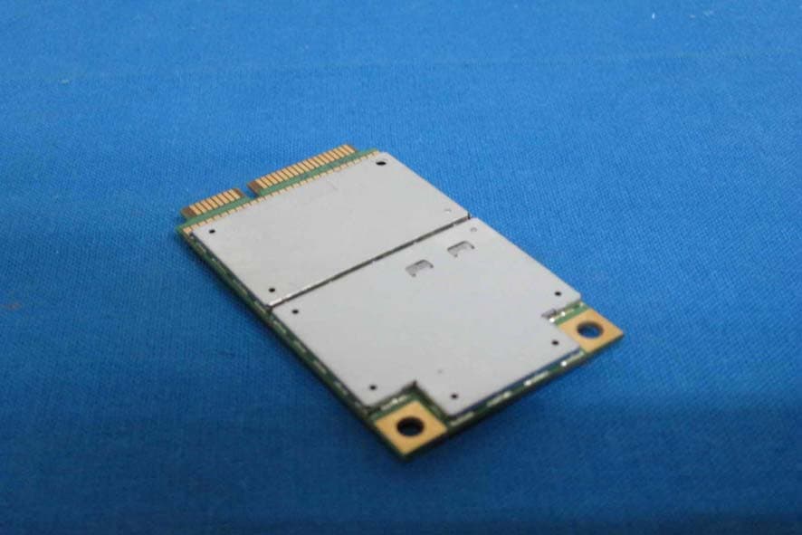
MAU050
Dec 02, 2012LTE Module
Equipment Class
PCB - PCS Licensed Transmitter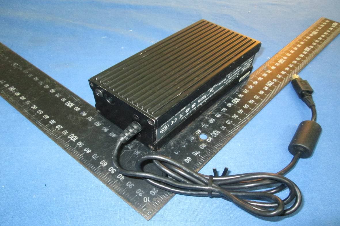
MAU048
Nov 04, 2012Notebook Computer
Equipment Class
NII - Unlicensed National Information Infrastructure TX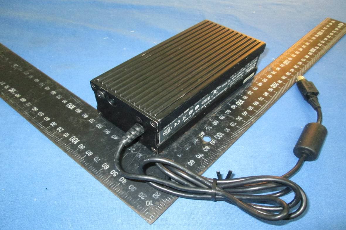
MAU049
Nov 04, 2012Notebook Computer
Equipment Class
DSS - Part 15 Spread Spectrum Transmitter
MAU046
Sep 05, 2012Wireless LAN Module
Equipment Class
DSS - Part 15 Spread Spectrum Transmitter
MAU047
Aug 29, 2012WWAN Module
Equipment Class
PCB - PCS Licensed Transmitter