MAU020Notebook PC with CDMA800, 1900
Getac Technology Corp.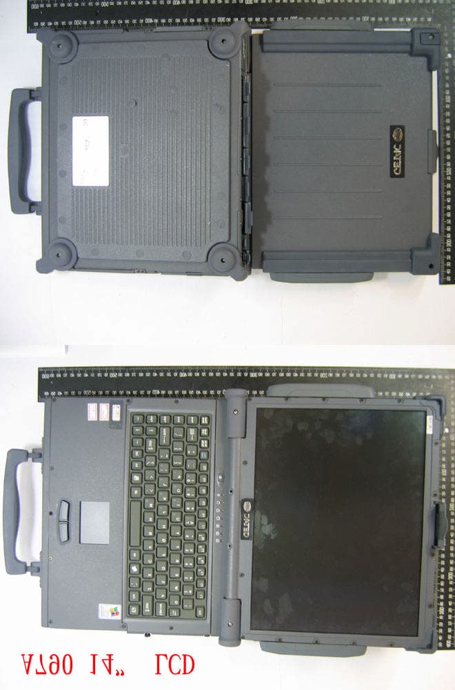
Click to zoom
Application Details
- Equipment Class
- PCB - PCS Licensed Transmitter
- Date of Grant
- Dec 16, 2006
- Application Purpose
- Original Equipment
- Date of Application
- Dec 14, 2006
- Equipment Note
- Notebook PC with CDMA800, 1900
- Frequency Range
- 824.73000000 - 848.19000000
- Company
- Getac Technology Corp.
- Country
- Taiwan
Documents & Files
Document Text
Text extracted from the exhibit documents filed with the FCC. Open a document above to read the original.
Users Manual
A790 Operation Manual Part Number: 7990 0114 3001 R00 (July 2006) TRADEMARKS All brand and product names are trademarks or registered trademarks of their respective companies. NOTE Information in this manual is subject to change without notice. i Table of Contents Preface......................................................................................vii Chapter 1 Getting Started......................................................1-1 Getting the Computer Running..............................................1-2 Unpacking.......................................................................1-2 Connecting to AC Power.................................................1-2 Opening the Cover..........................................................1-4 Turning On and Off the Computer..................................1-5 Taking a Look at the Computer.............................................1-6 Right-Side Components...................................................1-6 Left-Side Components.....................................................1-7 Rear Components............................................................1-8 Front Components.........................................................1-10 Top-open Components..................................................1-11 Where to Go from Here.......................................................1-13 Chapter 2 Operating Your Computer....................................2-1 Starting and Stopping the Computer.....................................2-2 Starting the Computer......................................................2-2 Stopping the Computer....................................................2-2 Using the Keyboard...............................................................2-4 Typewriter Keys..............................................................2-4 Cursor-Control Keys.......................................................2-5 Numeric Keypad..............................................................2-5 ii Euro Symbol...................................................................2-6 Windows Keys................................................................2-6 Function Keys.................................................................2-6 Fn Key.............................................................................2-7 Hot Keys..........................................................................2-7 Using the Touchpad..............................................................2-9 Configuring the Touchpad.............................................2-11 Using the Touchscreen (Optional).......................................2-12 Using the Hard Disk Drive..................................................2-14 Replacing the Hard Disk Drive.......................................2-14 Using the Video Features....................................................2-17 Configuring the Display Modes.....................................2-17 Using the Audio Features....................................................2-19 Connecting Audio Devices............................................2-20 Using the Communication Features.....................................2-21 Using the LAN...............................................................2-21 Using the Wireless LAN (Optional)................................2-22 Using the Modem...........................................................2-25 Using the Wireless Modem (Optional)...........................2-26 Using the GPS (Optional)..............................................2-27 Using the Bluetooth Feature (Optional)..........................2-28 Chapter 3 Managing Power...................................................3-1 AC Adapter...........................................................................3-2 Battery Pack..........................................................................3-3 Charging the Battery Pack................................................3-3 Initializing the Battery Pack..............................................3-4 Checking the Battery Level..............................................3-5 Replacing the Primary Battery Pack.................................3-5 Battery Low Signals and Actions.....................................3-7 Power Management...............................................................3-8 Hibernation......................................................................3-9 Power-Saving Tips.............................................................3-10 iii Chapter 4 Expanding Your Computer..................................4-1 Connecting an External Monitor............................................4-2 Connecting a Parallel Device.................................................4-3 Connecting a Serial Device...................................................4-4 Connecting an IR Device......................................................4-5 Connecting a USB Device.....................................................4-7 Connecting an IEEE 1394b Device........................................4-8 Using PC Cards.....................................................................4-9 PC Card Type..................................................................4-9 CardBus Support.............................................................4-9 Inserting and Removing a PC Card..................................4-9 System Memory Upgrade....................................................4-11 Chapter 5 Setup Configuration Utility (SCU)........................5-1 When and How to Use the SCU Program..............................5-2 When to Use....................................................................5-2 Starting SCU....................................................................5-2 Moving Around and Making Selections...........................5-4 Main Menu............................................................................5-5 Advanced Menu................................................................…
Text truncated - open the document above for the full version.
Cover Letter(s)
Sierra Wireless America, Inc 2290 Cosmos Ct. Carlsbad CA, 92011 Tel. 760-476-8700 Fax 760-476-8701 CONFIDENTIALITY LETTER DATE: 15 December, 2006 Federal Communications Commission Equipment Authorization Branch 7435 Oakland Mills Road Columbia, MD 21046 Re: Sierra Wireless, Request for Confidentiality FCC ID: MAU020 Applicant: Mitac To whom it may concern, Pursuant to the provisions of Sections 0.457 and 0.459 of the Commission’s rules (47 CFR §§ 0.457, 0.459), we are requesting the Commission to withhold the following attachments for the subject certification application as confidential documents from public disclosure indefinitely. Circuit Description – MC5720 Circuit Description Block Diagrams.pdf Block Diagram - MC5720 Circuit Description Block Diagrams.pdf Parts List - MC5720 Circuit Description Block Diagrams.pdf Tune up Alignment - MC5720 Tune up and Alignment Procedure.pdf Schematic - MC5720-SCHEMATIC These documents are specific to the embedded modem FCC ID: N7N-MC5720 contained within applicant device FCC ID: MAU019 and contain detailed system/ equipment descriptions and related information about the product in which Sierra Wireless considers to be proprietary, confidential, and a custom design and, otherwise, would not release to the general public. Since this design is a basis from which future technological products will evolve, Sierra Wireless considers that this information would be of benefit to its competitors, and that the disclosure of the information in these documents would give competitors an unfair advantage in the market. Sincerely Todd Van Cleave Manager Engineering Services Carlsbad Research & Development Sierra Wireless America, Inc.
Cover Letter(s)
No. 65, Ku Dai Keng St., Hsichih, Taipei 221, R.O. C. Tel: 886-2-2646-2550 FAX: 886-2-26464641 No. 120, Lane 180, San Ho Tsuen, Hsin Ho Rd. Lung-Tan Hsiang, Tao Yuan County 325, Taiwan, R.O.C. Tel: 886-3-407-1718 FAX:886-3-407-1738 Date: Nov. 23th, 2006 American Telecommunications Certification Body, Inc. 6731 Whittier Avenue Suite C110 McLean, VA 22101 RE: Certification Applications FCC ID: MAU020 Model: A790 We would like to apply for FCC Certification on the subject model (EUT). The EUT is a Notebook Personal Computer. We have uploaded the related document for the EUT onto your website. Please review the information we submitted and issue us a grant for the subject model. If you have any comments, please do not hesitate to contact us. Thank you for your attention to these matters. Sincerely, ________________ Eddy Hsiung / Director International Standards Laboratory No. 65, Ku Dai Keng St., Hsichih, Taipei 221, R.O. C. Tel: 886-2-2646-2550 FAX: 886-2-26464641 No. 120, Lane 180, San Ho Tsuen, Hsin Ho Rd. Lung-Tan Hsiang, Tao Yuan County 325, Taiwan, R.O.C. Tel: 886-3-407-1718 FAX:886-3-407-1738 FCC Labeling Requirements and Information Date: Nov. 23th, 2006 American Telecommunications Certification Body, Inc. 6731 Whittier Avenue Suite C110 McLean, VA 22101 RE: Certification Applications FCC ID: MAU020 Model: A790 The following label information is required by the FCC Rules and Regulations for certified devices. Please find marketing information required by the FCC Rules and Regulations as following: Label Requirements An intentional radiator device subject to certification by the FCC shall carry a warning label which includes the following statement: This device complies with Part 15 of the FCC Rules. Operation is subject to the following two conditions: (1) this device may not cause harmful interference, and (2) this device must accept any interference received, including interference that may cause undesired operation. The sample label shown shall be permanently affixed at a conspicuous location on the device and be readily visible to the user at the time of purchase. FCC ID: MAU020 This device complies with Part 15 of the FCC Rules. Operation is subject to the following two conditions: (1) this device may not cause harmful interference, and (2) this device must accept any interference received, including interference that may cause undesired operation. Sincerely, ________________ Eddy Hsiung / Director International Standards Laboratory No. 65, Ku Dai Keng St., Hsichih, Taipei 221, R.O. C. Tel: 886-2-2646-2550 FAX: 886-2-26464641 No. 120, Lane 180, San Ho Tsuen, Hsin Ho Rd. Lung-Tan Hsiang, Tao Yuan County 325, Taiwan, R.O.C. Tel: 886-3-407-1718 FAX:886-3-407-1738 Request for Confidentiality Date: Nov. 23th, 2006 American Telecommunications Certification Body, Inc. 6731 Whittier Avenue Suite C110 McLean, VA 22101 RE: Certification Applications FCC ID: MAU020 Model: A790 Please be advised that the following information is to be held confidential on behalf of MITAC TECHNOLOGY CORP. q Block Diagram q Schematics q Product Specification q Part List The application contains technical information which MITAC TECHNOLOGY CORP. deems to be trade secrets and proprietary. If made public, the information might be used to the disadvantage of the applicant in the market place. Thank you for your attention to this matter. Sincerely, ________________ Eddy Hsiung / Director International Standards Laboratory
Cover Letter(s)
American Telecommunications Certification Body Inc. 6731 Whittier Ave, McLean, VA 22101 December 1, 2006 RE: Mitac Technology Corp FCC ID: MAU020 I have a few comments on this Application. Depending on your responses, kindly understand there may be additional comments. 1.) It is not readily apparent that the Schematics cover the Part 22/24 transceiver. Please indicate which sheet of schematics I may find them. If they exist, my apologies. 2.) Please indicate where on the supplied Block Diagram I can find the Part 22/24 transceiver. Please also remember I need the block diagram of the transmitter portion to show electrical details. 3.) Your “Internal Photograph” on page 4 is difficult to read. The antennas may be 20cm or more away from the end user (excluding hands, wrists, feet and ankles) if this notebook PC is placed on the lab. This would then not require a SAR test. Please review. Please remember to make all your photographs large enough and clear enough to clearly see all construction details. 4.) Is the intent of the Sierra wireless card to use the mini-PCI slot in the PC (see block diagram)? If so, then my comment #2 (above) will be irrelevant. However, I will still need to have schematics and block diagram of the Sierra card. 5.) Please outline the positioning of the EUT on the SAR report plots (Appendix B). 6.) Since this filing is for a Part 22/24 Licensed transmitter and not Part 15, we will need a Tune- Up procedure and a Parts List. The most important item on the Tune-Up Procedure is the RF target Tune-Up values. There must be agreement between the RF target tune up values, the EMC report, and the SAR report. 7.) How was this tested – was the AT test command set native to the MC5720 used, or was a cell- site emulator used instead? If base station simulator, please provide additional details as to how the EUT was placed in a maximum power condition for testing. William H. Graff President and Director of Engineering mailto: [email protected] The items indicated above must be submitted before processing can continue on the above referenced application. Failure to provide the requested information may result in application termination. Correspondence should be considered part of the permanent submission and may be viewed from the Internet after a Grant of Equipment Authorization is issued. Please do not respond to this correspondence using the email reply button. In order for your response to be processed expeditiously, you must submit your documents through the AmericanTCB.com website. Also, please note that partial responses increase processing time and should not be submitted. Any questions about the content of this correspondence should be directed to the sender.
Cover Letter(s)
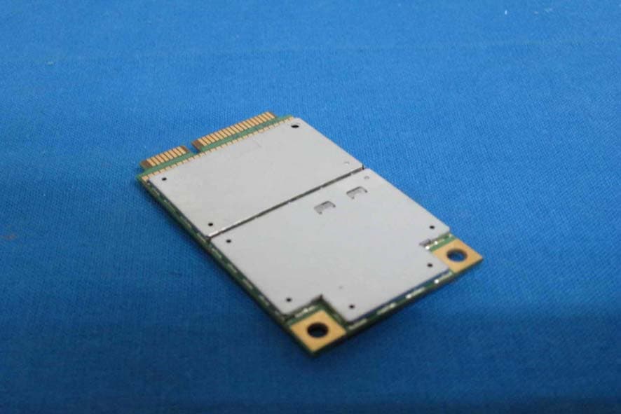
Dear Dennis, Here are the answers: 1 Please note that as per item 6 of the original comments, please provide the parts list for the module. ANS: Provided by client 2 Please remove the shields from the module and provide internal photos showing component location etc. ANS: Add a new photo on the last page of photo-internal. 3 if the parts list is to be confidential - please revise the request letter to include the parts list. ANS: A new AP-letters uploaded 4 Please note that in your response to Bill's comments about SAR you stated that the device antenna is closer than 20cm from the body and thus SAR had to be done (see item 3 original comments response). Please note that the manual specifically states that the device antenna must be more than 20 cm from the body (see pages 127 and 128 of the A790 manual). If as stated in your reply, the device antenna is closer than 20cm thus requiring SAR, please remove the minimul 20cm statement and correct the manual to properly address portable use. While specific SAR values may not be needed (even though recommended) you must still properly address the correct rf exposure environment. ANS: We have removed 20cm information from page 127 & 128 on the manual. Please refer to the updated manual 5 Please explain why the epsilon and sigma dielectric body references for the probe (sn 266) in the SAR report, page 12, do not match the calibrated values (i.e. cal data says 55.2 and 1.05 while the SAR report says 55.2 and 0.97). Please correct if necessary. ANS: We followed FCC Oet65 requirement, and epsilon value is 0.97. Epsilon 0.97 is a correct value but can not meet calibration value 1.05. I think that 1.05 is an incorrect value, we will ask calibration lab to correct this value. An updated Probe_835_Body calibration report has been uploaded FCC Oet65 Tissue Dielectric Parameters for Head and Body Phantoms: Target Frequency Head Body (MHz) ε r σ (S/m) ε r σ (S/m) 150 52.3 0.76 61.9 0.80 300 45.3 0.87 58.2 0.92 450 43.5 0.87 56.7 0.94 835 41.5 0.90 55.2 0.97 900 41.5 0.97 55.0 1.05 915 41.5 0.98 55.0 1.06 1450 40.5 1.20 54.0 1.30 1610 40.3 1.29 53.8 1.40 1800 – 2000 40.0 1.40 53.3 1.52 2450 39.2 1.80 52.7 1.95 3000 38.5 2.40 52.0 2.73 5800 35.3 5.27 48.2 6.00 (ε r = relative permittivity, σ = conductivity and ρ = 1000 kg/m 3 ) Please review Daphne 12/15/2006
Cover Letter(s)
HI Daphne Please address the following issues: 1 Please note that as per item 6 of the original comments, please provide the parts list for the module. 2 Please remove the shields from the module and provide internal photos showing component location etc. 3 if the parts list is to be confidential - please revise the request letter to include the parts list. 4 Please note that in your response to Bill's comments about SAR you stated that the device antenna is closer than 20cm from the body and thus SAR had to be done (see item 3 original comments response). Please note that the manual specifically states that the device antenna must be more than 20 cm from the body (see pages 127 and 128 of the A790 manual). If as stated in your reply, the device antenna is closer than 20cm thus requiring SAR, please remove the minimul 20cm statement and correct the manual to properly address portable use. While specific SAR values may not be needed (even though recommended) you must still properly address the correct rf exposure environment. 5 Please explain why the epsilon and sigma dielectric body references for the probe (sn 266) in the SAR report, page 12, do not match the calibrated values (i.e. cal data says 55.2 and 1.05 while the SAR report says 55.2 and 0.97). Please correct if necessary. Thanks Dennis Ward Evaluation Engineer American TCB Certification Resource for the Wireless Industry www.atcb.com 703-847-4700 fax 703-847-6888 direct - 703-880-4841 cell - 209-769-8316 NOTICE: This E-Mail message and any attachment may contain privileged or company proprietary information. If you received this message in error, please return to the sender. -----Original Message----- From: Dward ATCB [mailto:[email protected]] Sent: 12/11/2006 11:36 AM To: '[email protected]'; '[email protected]' Cc: '[email protected]'; '[email protected]'; '[email protected]' Subject: RE: www.AmericanTCB.com ATCB004280 | MAU020 | | | MAU020_ATCB004280 Also, when providing the parts list for the licensed transmitter, unless specifically stated in the confidentiality request, it will not be confidential. Thanks Dennis Ward Evaluation Engineer American TCB Certification Resource for the Wireless Industry www.atcb.com 703-847-4700 fax 703-847-6888 direct - 703-880-4841 cell - 209-769-8316 NOTICE: This E-Mail message and any attachment may contain privileged or company proprietary information. If you received this message in error, please return to the sender. -----Original Message----- From: Dward ATCB [mailto:[email protected]] Sent: 12/11/2006 11:32 AM To: '[email protected]'; '[email protected]' Cc: '[email protected]'; '[email protected]'; '[email protected]' Subject: RE: www.AmericanTCB.com ATCB004280 | MAU020 | | | MAU020_ATCB004280 HI Daphne Please note that while you have provided the tune up procedure, you have not provided the parts list. Please provide the required parts list for the licensed device. Thanks Dennis Ward Evaluation Engineer American TCB Certification Resource for the Wireless Industry www.atcb.com 703-847-4700 fax 703-847-6888 direct - 703-880-4841 cell - 209-769-8316 NOTICE: This E-Mail message and any attachment may contain privileged or company proprietary information. If you received this message in error, please return to the sender.
Cover Letter(s)
ATCB comment Answer: Dear Bill, Here are the answers: 1.) It is not readily apparent that the Schematics cover the Part 22/24 transceiver. Please indicate which sheet of schematics I may find them. If they exist, my apologies. ANS: Sierra doesn’t provide this to us. They hope to offer to you directly. 2.) Please indicate where on the supplied Block Diagram I can find the Part 22/24 transceiver. Please also remember I need the block diagram of the transmitter portion to show electrical details. ANS: Sierra doesn’t provide this to us. They hope to offer to you directly. 3.) Your “Internal Photograph” on page 4 is difficult to read. The antennas may be 20cm or more away from the end user (excluding hands, wrists, feet and ankles) if this notebook PC is placed on the lab. This would then not require a SAR test. Please review. Please remember to make all your photographs large enough and clear enough to clearly see all construction details. ANS: 2 more clear shots on eut-5 and eut-6 about the antennas location. It needs SAR test because it distance between antenna to end user is less than 20cm. 4.) Is the intent of the Sierra wireless card to use the mini-PCI slot in the PC (see block diagram)? If so, then my comment #2 (above) will be irrelevant. However, I will still need to have schematics and block diagram of the Sierra card. ANS: Sierra doesn’t provide this to us. They hope to offer to you directly. 5.) Please outline the positioning of the EUT on the SAR report plots (Appendix B). ANS: Please refer the EUT position in appendix B of SAR report, also you can find the position on page 22 of SAR report <06LR032SAR-F> 6.) Since this filing is for a Part 22/24 Licensed transmitter and not Part 15, we will need a Tune- Up procedure and a Parts List. The most important item on the Tune-Up Procedure is the RF target Tune-Up values. There must be agreement between the RF target tune up values, the EMC report, and the SAR report. ANS: Sierra doesn’t provide these to us. They hope to offer to you directly. 7.) How was this tested – was the AT test command set native to the MC5720 used, or was a cellsite emulator used instead? If base station simulator, please provide additional details as to how the EUT was placed in a maximum power condition for testing. ANS: We used Agilent 8960 base station to connect EUT, and set maximum power of FTAP and RTAP in RC3 (EVDO mode) measurement. Please review. Best regards, Daphne
External Photos
Appendix D of Report Number: ISL-06LR032SAR-F International Standards Laboratory -1- EUT-1. EUT-2. Appendix D of Report Number: ISL-06LR032SAR-F International Standards Laboratory -2- EUT-3.
ID Label/Location Info
Label Location Location
Internal Photos
Appendix D of Report Number: ISL-06LR032SAR-F International Standards Laboratory -2- EUT-3. Appendix D of Report Number: ISL-06LR032SAR-F International Standards Laboratory -3- EUT-4. Appendix D of Report Number: ISL-06LR032SAR-F International Standards Laboratory -4- EUT-5. Appendix D of Report Number: ISL-06LR032SAR-F International Standards Laboratory -5- EUT-6. Appendix D of Report Number: ISL-06LR032SAR-F International Standards Laboratory -6- EUT-7. Appendix D of Report Number: ISL-06LR032SAR-F International Standards Laboratory -7- EUT-8.
RF Exposure Info
Report Number: ISL-06LR032SAR-F Issue Date: 2006/11/14 HC LAB:NVLAP:200234-0;VCCI: R-341,C-354; NEMKO:ELA 113A;BSMI:SL2-IN-E-0037;SL2-R1-E-0037;TAF:1178; IC:IC4067 LT LAB: NVLAP:200234-0;VCCI: R-1435,C-1440;NEMKO:ELA 113B; BSMI:SL2-IN-E-0013;TAF:0997; IC:IC4164-1 ISL-T10-R4-14 SAR Test Report of Product Name Notebook Personal Computer Model A790 Applied by: MITAC Technology Corporation 4F, No.1, R&D Road 2, Hsinchu Science-Based industrial Park, Hsinchu 300 Taiwan,R. O. C. Test Performed by: International Standards Laboratory No. 120, Lane 180, San Ho Tsuen, Hsin Ho Rd. Lung-Tan Hsiang, Tao Yuan County 325 Taiwan, R.O.C. Tel:(03)407-1718 Fax:(03)407-1738 - i - International Standards Laboratory Report Number: ISL-06LR032SAR-F HC LAB:NVLAP:200234-0;VCCI: R-341,C-354; NEMKO:ELA 113A;BSMI:SL2-IN-E-0037;SL2-R1-E-0037;TAF:1178; IC:IC4067 LT LAB: NVLAP:200234-0;VCCI: R-1435,C-1440;NEMKO:ELA 113B; BSMI:SL2-IN-E-0013;TAF:0997; IC:IC4164-1 Contents of Report 1. General..................................................................................................................................1 1.1 Certification of Accuracy of Test Data.........................................................................1 2. Description of Equipment Under Test (EUT)......................................................................2 2.1 Test Environment..........................................................................................................2 3. SAR Measurement System...................................................................................................3 3.1 ALSAS-10U System Description.................................................................................3 3.1.1 Applications..........................................................................................................3 3.1.2 Area Scans............................................................................................................3 3.1.3 Zoom Scan (Cube Scan Averaging).....................................................................4 3.1.4 ALSAS-10U Interpolation and Extrapolation Uncertainty..................................4 3.2 Isotropic E-Field Probe.................................................................................................5 3.2.1 Isotropic E-Field Probe Specification...................................................................6 3.3 Boundary Detection Unit and Probe Mounting Device................................................6 3.4 Daq-Paq (Analog to Digital Electronics)......................................................................7 3.5 Axis Articulated Robot.................................................................................................7 3.6 ALSAS Universal Workstation....................................................................................8 3.7 Universal Device Positioner........................................................................................8 3.8 Phantom Types.............................................................................................................9 3.8.1 APREL Laboratories Universal Phantom.............................................................9 4. Tissue Simulating Liquid....................................................................................................10 4.1 The composition of the tissue simulating liquid.........................................................10 4.2 Tissue Calibration Result............................................................................................10 4.3 Tissue Dielectric Parameters for Head and Body Phantoms......................................12 5. SAR Measurement Procedure.............................................................................................13 5.1 SAR System Validation..............................................................................................13 5.1.1 Validation Dipoles..............................................................................................13 5.1.2 Validation Result................................................................................................14 5.2 Arrangement Assessment Setup.................................................................................15 5.2.1 Test Positions of Device Relative to Head.............................................................15 5.2.2 Definition of the “Cheek” Position.........................................................................15 5.2.3 Definition of the “Tilted” Position.........................................................................17 5.2.4 Test Positions for body-worn..................................................................................17 5.3 SAR Measurement Procedure.....................................................................................18 6. SAR Exposure Limits.........................................................................................................19 7. Test Equipment List............................................................................................................20 8. Measurement Uncertainty...................................................................................................21 9. Test Result Summary..........................................................................................................22 9.1 CDMA2000 (800MHz) Test Result...........................................................................22 9.2 CDMA2000(1900MHz) Test Result..........................................................................23 10. Appendix A: SAR System Validation Data....................................................................24 11. Appendix B: SAR measurement Data............................................................................24 12. Appendix C: Photographs of Test Setup........................................................................24 13. Appendix D: Photographs of EUT..............…
Text truncated - open the document above for the full version.
RF Exposure Info
Appendix A of Report Number: ISL-06LR032SAR-F International Standards Laboratory Appendix A SAR System Validation Data of Product Name Notebook Personal Computer Model A790 Appendix A of Report Number: ISL-06LR032SAR-F International Standards Laboratory - 1 - 1 835 MHz System Validation Data Report Date : 24-Oct-2006 Measurement Date : 24-Oct-2006 Product Data Device Name : Dipole-835 Serial No. : Validation Type : Dipole Model : Standard Frequency : 835.00 MHz Max. Transmit Pwr : 1 W Drift Time : 0 min(s) Length : 161 mm Width : 3.6 mm Depth : 89.8 mm Antenna Type : Internal Power Drift-Start : 10.371 W/kg Power Drift-Finish: 10.225 W/kg Power Drift (%) : -1.404 Phantom Data Name : APREL-Uni Type : Uni-Phantom Size (mm) : 280 x 280 x 200 Location : Center Tissue Data Type : HEAD Serial No. : 835HEAD Frequency : 835.00 MHz Last Calib. Date : 24-Oct-2006 Temperature : 23.60 °C Ambient Temp. : 23.80 °C Humidity : 56.00 RH% Epsilon : 43.09 F/m Sigma : 0.92 S/m Density : 1000.00 kg/cu. m Probe Data Name : E-field Probe Model : ALS-E-020 Type : E-Field Triangle Serial No. : 266 Last Calib. Date : 22-Jun-2006 Frequency : 835.00 MHz Duty Cycle Factor: 1 Conversion Factor: 6.6 Probe Sensitivity: 1.20 1.20 1.20 μV/(V/m) 2 Compression Point: 95.00 mV Offset : 1.56 mm Measurement Data Crest Factor…
Text truncated - open the document above for the full version.
Contact Information
Applicant
Vincent Hsieh(Senior Engineer)
Technical Specifications
| # | Rule Parts | Frequency Range | Power Output | Emission | Tolerance |
|---|---|---|---|---|---|
| 2 | 22H | 824.73 MHz - 848.19 MHz | 204.00 mW | 1M25F9W | 0.1 ppm |
Other Applications from Getac Technology Corp.
MAU050
Dec 02, 2012LTE Module
Equipment Class
PCB - PCS Licensed Transmitter
MAU048
Nov 04, 2012Notebook Computer
Equipment Class
NII - Unlicensed National Information Infrastructure TX
MAU049
Nov 04, 2012Notebook Computer
Equipment Class
DSS - Part 15 Spread Spectrum Transmitter
MAU046
Sep 05, 2012Wireless LAN Module
Equipment Class
DSS - Part 15 Spread Spectrum Transmitter
MAU047
Aug 29, 2012WWAN Module
Equipment Class
PCB - PCS Licensed Transmitter