MAU021Notebook with WLAN
Getac Technology Corp.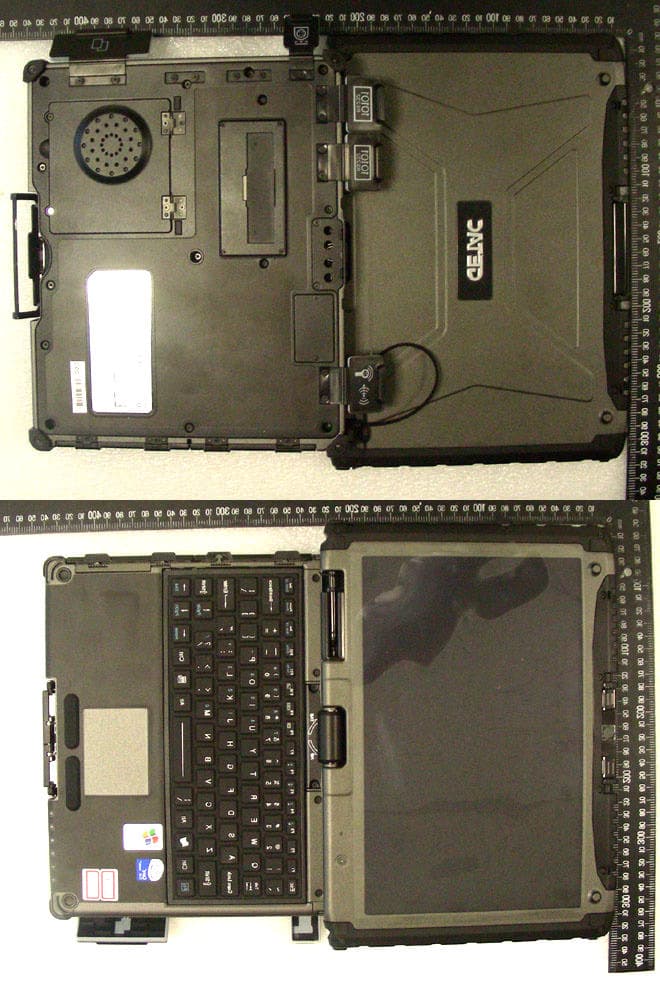
Click to zoom
Application Details
- Equipment Class
- NII - Unlicensed National Information Infrastructure TX
- Date of Grant
- Mar 29, 2007
- Application Purpose
- Original Equipment
- Date of Application
- Mar 29, 2007
- Equipment Note
- Notebook with WLAN
- Frequency Range
- 5260.00000000 - 5320.00000000
- Company
- Getac Technology Corp.
- Country
- Taiwan
Documents & Files
Document Text
Text extracted from the exhibit documents filed with the FCC. Open a document above to read the original.
Users Manual
V100 User’s Manual IMPORTANT : This User’s Manual is for Safety Approval purpose only. This is not intended as final release for mass production. (February 2007) TRADEMARKS All brand and product names are trademarks or registered trademarks of their respective companies. NOTE The information in this manual is subject to change without notice. i Table of Contents Preface...................................................................................v Notational Conventions...................................................vi Chapter 1 Getting Started................................................1-1 Getting the Computer Running...........................................1-2 Unpacking....................................................................1-2 Connecting to AC Power...............................................1-2 Opening and Closing the Cover......................................1-3 Turning On and Off the Computer.................................1-3 Taking a Look at the Computer.........................................1-5 Right-Side Components.................................................1-5 Left-Side Components..................................................1-6 Rear Components.........................................................1-7 Front Components........................................................1-8 Bottom Components.....................................................1-9 Top-open Components................................................1-10 Where to Go from Here..................................................1-12 Chapter 2 Operating Your Computer...............................2-1 Starting and Stopping the Computer...................................2-2 Starting the Computer...................................................2-2 Stopping the Computer..................................................2-2 Using the Keyboard..........................................................2-4 Typewriter Keys...........................................................2-4 Cursor-Control Keys.....................................................2-4 Numeric Keypad..........................................................2-5 Function Keys..............................................................2-5 Fn Key........................................................................2-6 ii Hot Keys.....................................................................2-6 Using the Touchpad..........................................................2-8 Configuring the Touchpad.............................................2-9 Using the Touchscreen....................................................2-10 Using the Active Digitizer Feature....................................2-11 Using the Hard Disk Drive..............................................2-12 Replacing the Hard Disk Drive.....................................2-12 Using the Video Features.................................................2-14 Configuring the Display Modes....................................2-14 Using the Audio Features................................................2-16 Connecting Audio Devices...........................................2-16 Using the Communication Features..................................2-17 Using the Modem.......................................................2-17 Using the LAN...........................................................2-17 Using the Wireless LAN..............................................2-18 Using the Bluetooth Feature (Optional).........................2-21 Using the GPS (Optional)............................................2-24 Chapter 3 Managing Power..............................................3-1 AC Adapter......................................................................3-2 Battery Pack....................................................................3-3 Charging the Battery Pack.............................................3-3 Initializing the Battery Pack...........................................3-4 Battery Automatic Calibration Utility..............................3-5 Checking the Battery Level............................................3-7 Replacing the Battery Pack............................................3-7 Battery Low Signals and Actions....................................3-8 Power Management..........................................................3-9 Hibernation................................................................3-10 Power-Saving Tips.........................................................3-11 Chapter 4 Expanding Your Computer..............................4-1 Connecting an External Monitor (Optional).........................4-2 Connecting a Serial Device................................................4-3 Connecting a USB Device.................................................4-4 iii Using PC Cards................................................................4-5 PC Card Type..............................................................4-5 CardBus Support..........................................................4-5 Inserting and Removing a PC Card.................................4-5 Using the Card Reader......................................................4-7 System Memory Upgrade..................................................4-8 Chapter 5 Using BIOS Setup............................................5-1 When and How to Use BIOS Setup...................................5-2 When to Use................................................................5-2 Starting BIOS Setup......................................................5-2 Moving Around and Making Selections...........................5-4 Main Menu......................................................................5-5 Advanced Menu...............................................................5-6 Security Menu..................................................................5-9 Boot Menu....................................................................5-10 Exit Menu................…
Text truncated - open the document above for the full version.
Attestation Statements
Date: Feb. 12th, 2007 Model: V100 FCC ID: MAU021 Dear Sir, We would like to declare that our product Notebook Personal Computer (with Intel Wireless LAN Module:WM3945ABG), Model: V100, FCC ID: MAU021 was a device which without radar detection. The uniform spreading mechanism was follow the master device (ex. access point) after radar waveform is detected . Thanks for your help and do not hesitate to contact us if you have any further questions. _______________________ Power Shao MITAC Technology Corporation
Cover Letter(s)
No. 65, Ku Dai Keng St., Hsichih, Taipei 221, R.O. C. Tel: 886-2-2646-2550 FAX: 886-2-26464641 No. 120, Lane 180, San Ho Tsuen, Hsin Ho Rd. Lung-Tan Hsiang, Tao Yuan County 325, Taiwan, R.O.C. Tel: 886-3-407-1718 FAX:886-3-407-1738 Date: Feb. 9th, 2007 American Telecommunications Certification Body, Inc. 6731 Whittier Avenue Suite C110 McLean, VA 22101 RE: Certification Applications FCC ID: MAU021 Model: V100 We would like to apply for FCC Certification on the subject model (EUT). The EUT is a Notebook Personal Computer built in WLAN a+b+g Module. We have uploaded the related document for the EUT onto your website. Please review the information we submitted and issue us a grant for the subject model. If you have any comments, please do not hesitate to contact us. Thank you for your attention to these matters. Sincerely, ________________ Eddy Hsiung / Director International Standards Laboratory No. 65, Ku Dai Keng St., Hsichih, Taipei 221, R.O. C. Tel: 886-2-2646-2550 FAX: 886-2-26464641 No. 120, Lane 180, San Ho Tsuen, Hsin Ho Rd. Lung-Tan Hsiang, Tao Yuan County 325, Taiwan, R.O.C. Tel: 886-3-407-1718 FAX:886-3-407-1738 FCC Labeling Requirements and Information Date: Feb. 9th, 2007 American Telecommunications Certification Body, Inc. 6731 Whittier Avenue Suite C110 McLean, VA 22101 RE: Certification Applications FCC ID: MAU021 Model: V100 The following label information is required by the FCC Rules and Regulations for certified devices. Please find marketing information required by the FCC Rules and Regulations as following: Label Requirements An intentional radiator device subject to certification by the FCC shall carry a warning label which includes the following statement: This device complies with Part 15 of the FCC Rules. Operation is subject to the following two conditions: (1) this device may not cause harmful interference, and (2) this device must accept any interference received, including interference that may cause undesired operation. The sample label shown shall be permanently affixed at a conspicuous location on the device and be readily visible to the user at the time of purchase. FCC ID: MAU021 This device complies with Part 15 of the FCC Rules. Operation is subject to the following two conditions: (1) this device may not cause harmful interference, and (2) this device must accept any interference received, including interference that may cause undesired operation. Sincerely, ________________ Eddy Hsiung / Director International Standards Laboratory No. 65, Ku Dai Keng St., Hsichih, Taipei 221, R.O. C. Tel: 886-2-2646-2550 FAX: 886-2-26464641 No. 120, Lane 180, San Ho Tsuen, Hsin Ho Rd. Lung-Tan Hsiang, Tao Yuan County 325, Taiwan, R.O.C. Tel: 886-3-407-1718 FAX:886-3-407-1738 Request for Confidentiality Date: Feb. 9th, 2007 American Telecommunications Certification Body, Inc. 6731 Whittier Avenue Suite C110 McLean, VA 22101 RE: Certification Applications FCC ID: MAU021 Model: V100 Please be advised that the following information is to be held confidential on behalf of MITAC TECHNOLOGY CORP. q Block Diagram- “WM3945ABG Block Diagram.pdf”, “V100 Block and Schematics.pdf” q Schematics- “WM3945ABG_Schematic.pdf”; “V100 Block and Schematics.pdf” q Operation Description-(Product Specification)- “Marketing brochure 3945ABG v1.pdf” The application contains technical information which MITAC TECHNOLOGY CORP. deems to be trade secrets and proprietary. If made public, the information might be used to the disadvantage of the applicant in the market place. Thank you for your attention to this matter. Sincerely, ________________ Eddy Hsiung / Director International Standards Laboratory
Cover Letter(s)
Dear Tim, Here are our answers, 1) FYI..In the future, on 731 form please list actual center channels of the frequency band and not simply the band of operation for 802.11a emissions (5180 - 5320, 5745 - 5825). Ans: Thanks for the information. 2) Please note that 15.247 power appears to follow an average test method. Therefore all emissions are required to be 30 dB down (not 20 dB) as cited in other areas of the report (i.e. spurious, bandedge, etc. - although it appears this may have only been applied for band edge Section 8.6, 8.13, 8.20). Note that page 48 suggests 30 dB may not be compliant. Please review/correct. Ans: Please refer to the updated report. 3) Test results for 802.11g bandwidth clearly shows an 802.11b waveform in section 8.10. Please confirm that 802.11g is working properly and also correct any necessary tests affected. Ans: Please refer to the updated report. 4) Note that a reading in section 4.1.15 for average actually shows a value in excess of 54 dBuV/m at 7229 MHz. Please review. Ans: Please refer to the updated report. 5) Power excursion appears to use method 3 from the UNII Public Notice, when it should follow what was used to measure power (method 1). Ans: Please refer to the updated report. 6) Section 7.1.24 does not appear to be calculated properly. Please review. Ans: Please refer to the updated report. 7) Please provide information regarding compliance to 15.407(c). If this information has already been provided, kindly show where this information is located. Ans: The indoor use wording have been added on page 113(b-6) DFS Related: 8) Operational description states the Architecture may use Infrastructure or ad hoc (peer-to-peer). This conflicts with the DFS report. Please review. Note that TCB's may only process devices that operate in 5250 - 5350 and/or 5470 - 5725 MHz that are clients only (no ad-hoc or peer-to-peer). Please review. Ans: I have contacted Intel, and got their grant with remarks as following (refer to last page for the grant) This device complies with the Dynamic Frequency Selection (DFS) requirements of Report andOrder FCC 03-287 as a Client only without Radar Detection 9) Users Manual information does not appear to clearly define (for USA) that the device may only be used indoors for 5150-5250 MHz. Please review. Ans: The indoor use wording have been added on page 113(b-6) 10) 1) How is DFS software/firmware protected to ensure users do not have access to DFS settings. Additionally, for USA, devices may not have country selection as this would not be allowed under 15.15. Please explain and also clarify how users are prevented from disabling DFS and/or transmitting in frequencies not authorized in United States? Ans: same as item 8 11) Please submit expanded plots for the channel transmission closing time demonstrating that the device vacates the channel in the required 200 ms. these plots should not have a sweep greater than 600 ms. Ans: Please see report page 16, T1 denote the Radar signal, T2 denote the 200th ms from T1 and there are some traffic signal located between T2 and T3. So that the channel closing transmission time did not less than 200ms and then 600ms plot is not necessary. Please review Daphne 3/16/07 TCB GRANT OF EQUIPMENT AUTHORIZATION TCB Certification Issued Under the Authority of the Federal Communications Commission By: American TCB, Inc. 6731 Whittier Avenue Suite C110 McLean, VA 22101 Date of Grant: 11/07/2006 Application Dated: 11/06/2006 Intel Corporation 2111 NE 25th Avenue JF3-302 Hillsboro, OR 97124 Attention: Robert Paxman , Sr. Compliance Engineer NOT TRANSFERABLE EQUIPMENT AUTHORIZATION is hereby issued to the named GRANTEE, and is VALID ONLY for the equipment identified hereon for use under the Commission's Rules and Regulations listed below. FCC IDENTIFIER: PD9WM3945ABG Name of Grantee: Intel Corporation Equipment Class:Unlicensed National Information Infrastructure TX Notes:Intel PRO/Wireless 3945ABG Network Connection Grant Notes FCC Rule Parts Frequency Range (MHZ) Output Watts Frequency Tolerance Emission Designator 15E5180.0 - 5240.0 0.048 15E5260.0 - 5320.0 0.068 Power Output listed is Conducted. Modular approval. This module is approved for use in mobile only configurations. This module must be installed by the OEM or OEM integrator. Instructions on installation of this module may not be provided to the end user. Only those antenna(s) tested with the device or similar antenna(s) with equal or lesser gain may be used with this transmitter. This transmitter is restricted to indoor use in the 5150MHz to 5250MHz frequency range. The antenna used for this transmitter must be installed to provide a separation distance of at least 20 cm from all persons and must not be co-located or operating in conjunction with any other antenna or transmitter. End-users and installers must be provided with antenna installation instructions and transmitter operating conditions for satisfying RF exposure compliance. This device complies with the Dynamic Frequency Selection (DFS) requirements of Report andOrder FCC 03-287 as a Client only without Radar Detection.
Cover Letter(s)
RE: Mitac Technology Corp. FCC: MAU021 Dear Tim, Here are our answers, EMC/SAR 1) FYI....In future application, please note that if average power techniques are used for 15.247, then the limits on page 21,45 & 69 should also cite >30 dB. ANS: Thanks for the information. . 2) FYI...While the beginning of each SAR plot section showed the test date, please note that the FCC expects test dates to be provided on all SAR plots. Please consider this in the future. ANS: Thanks for the information 3) FYI....Conductivity for > 5 GHz should been < 2.5%, not 5% as the limits show. Note the data shows compliance to 2.5% for body tissues, but please adjust the limits in the future. ANS: Thanks for the information. But according SAR measurement requirements you mailed on page 4. Is there any change in FCC? 4) Section 3.2 of the SAR report cites a 5 mm scan height. However 5 GHz typically requires closer measurements of 2.5 mm and closest 2 points are < 5 mm for > 4.5 GHz. This information could not be found in the report. Please comment. ANS: We have modified the report on 3.1.5 & 3.1.6 , please refer the updated SAR report. 5) As part of the SAR validation > 5 GHz, the FCC asks that the extrapolated peak SAR value at the phantom surface above the dipole feed-point should be within 15% of the calibrated target value. Information on this was not found. ANS: We have modified the report on 3.1.5 & 3.1.6 , please refer the updated SAR report. DFS Related: 6) While we understand you response to item 11, please note that the request for a expanded plot (not have a sweep greater than 600 ms) for the channel transmission closing time demonstrating that the device vacates the channel in the required 200 ms is a new requirement from the FCC. We have recently received RT’s on all DFS results shown similar to those provided asking for this. Additionally, training on February from the FCC requires it. See the following: NOTE: Please ensure or label which signals are from the master and which are from the client as levels were not clearly distinguishable. Note the FCC gave the following as an example below which clearly shows 2 levels. The current plot is hard to determine these. ANS: (This DFS report is performed by ADT. They ask their TCB and got the following information. I am very sorry if this is not what you want. ) This comment is unreasonable. There is no document require test report label the traffic signal from Master or Client. And, Master already got FCC certificate and then the traffic signal shall all comply the requirements.
Cover Letter(s)
EMC/SAR 1) Please provide information regarding compliance to 15.407(c). If this information has already been provided, kindly show where this information is located. 15.407(c): (c) The device shall automatically discontinue transmission in case of either absence of information to transmit or operational failure. These provisions are not intended to preclude the transmission of control or signalling information or the use of repetitive codes used by certain digital technologies to complete frame or burst intervals. Applicants shall include in their application for equipment authorization a description of how this requirement is met. Data transmission is always initiated by software, which is then passed down through the MAC, through the digital and analog baseband, and finally to the RF chip. Several special packets (ACKs, CTS, PSPoll, etc...) are initiated by the MAC. These are the only ways the digital baseband portion will turn on the RF transmitter, which it then turns off at the end of the packet. Therefore, the transmitter will be on only while one of the aforementioned packets is being transmitted. DFS Related: 2) The previous response to item 8 suggests that the device was granted as a client only for the 5260 – 5320 MHz band. However this does not appear to explain why the operational description states the device utilizes infrastructure or ad hoc (peer to peer) modes. Please explain further or clarify. (i.e. is the reference to ad hoc/peer to peer only for other modes such as 802.11b or the 5725 – 5850 band and therefore the 5260 – 5320 MHz band only operates in infrastructure mode?). Without clarification of the Intel Product Overview supplied, it appears the card is capable of ad hoc/peer to peer in the 5250 – 5350 MHz band. The Intel PRO/Wireless 3945ABG Network Connection operates as follows: Channels 1 – 11, 2412 – 2462MHz, active scanning, infrastructure and adhoc modes are allowed. Channels 36 – 64, 5180 – 5320MHz, passive scanning and infrastructure mode is only allowed, the WLAN card only operates as a client. Channels 149 – 165, 5745 – 5850MHz, passive scanning and infrastructure mode is only allowed, the WLAN card only operates as a client. 3) The previous response to item 10 simply references the previous approval of the card. Please note that each application must stand on its own, therefore this information should be provided for this application and not simply reference the previous approval. Please explain: How is DFS software/firmware protected to ensure users do not have access to DFS settings. Additionally, for USA, devices may not have country selection as this would not be allowed under 15.15. Please explain and also clarify how users are prevented from disabling DFS and/or transmitting in frequencies not authorized in United States? The Intel PRO/Wireless 3945ABG Network Connection channel operation, allowed channels and output power information is programmed into the EEPROM and can not be changed by the end user. The user is not given the capabilty to alter any of these parameters within the EEPROM.
Cover Letter(s)
These 2 typical plots only show the the Client device's traffic signal. When Master device detected Radar signal sucessfully and ceased streaming, the Client device stoped transmitting soon. Further more, as the Master device detected Radar signal in quiet period (Rx period), the action of channel closing was happened immediately. ========================================================================================== Best Regards. §d ̈ÎøÊ / Ellis Wu E-mail : [email protected] ̧Û«H¬ì§Þ / ADT Corp. TEL : +886 3 3183232 #1624 FAX : +886 3 3270892
External Photos
International Standards Laboratory Report Number: ISL-07LR006P -1- EUT-1. International Standards Laboratory Report Number: ISL-07LR006P -2- EUT-2. International Standards Laboratory Report Number: ISL-07LR006P -3- EUT-3. International Standards Laboratory Report Number: ISL-07LR006P -4- EUT-4.
ID Label/Location Info
V100 Label Location LABEL
Internal Photos
International Standards Laboratory Report Number: ISL-07LR006P -5- EUT-5. International Standards Laboratory Report Number: ISL-07LR006P -6- EUT-6. International Standards Laboratory Report Number: ISL-07LR006P -7- EUT-7. International Standards Laboratory Report Number: ISL-07LR006P -8- EUT-8. International Standards Laboratory Report Number: ISL-07LR006P -9- EUT-9. International Standards Laboratory Report Number: ISL-07LR006P -10- EUT-10. International Standards Laboratory Report Number: ISL-07LR006P -11- EUT-11. International Standards Laboratory Report Number: ISL-07LR006P -12- EUT-12. International Standards Laboratory Report Number: ISL-07LR006P -13- EUT-13. International Standards Laboratory Report Number: ISL-07LR006P -14- EUT-14.
Internal Photos
International Standards Laboratory Report Number: ISL-07LR006P -15- EUT-15. International Standards Laboratory Report Number: ISL-07LR006P -16- EUT-16. International Standards Laboratory Report Number: ISL-07LR006P -17- EUT-17. International Standards Laboratory Report Number: ISL-07LR006P -18- EUT-18. International Standards Laboratory Report Number: ISL-07LR006P -19- EUT-19. International Standards Laboratory Report Number: ISL-07LR006P -20- EUT-20. International Standards Laboratory Report Number: ISL-07LR006P -21- EUT-21. International Standards Laboratory Report Number: ISL-07LR006P -22- EUT-22. International Standards Laboratory Report Number: ISL-07LR006P -23- EUT-23. International Standards Laboratory Report Number: ISL-07LR006P -24- EUT-24.
Internal Photos
International Standards Laboratory Report Number: ISL-07LR006P -25- EUT-25. International Standards Laboratory Report Number: ISL-07LR006P -26- EUT-26. International Standards Laboratory Report Number: ISL-07LR006P -27- EUT-27. International Standards Laboratory Report Number: ISL-07LR006P -28- EUT-28. International Standards Laboratory Report Number: ISL-07LR006P -29- EUT-29. International Standards Laboratory Report Number: ISL-07LR006P -30- EUT-30. International Standards Laboratory Report Number: ISL-07LR006P -31- EUT-31. International Standards Laboratory Report Number: ISL-07LR006P -32- EUT-32. International Standards Laboratory Report Number: ISL-07LR006P -33- EUT-33. International Standards Laboratory Report Number: ISL-07LR006P -34- EUT-34.
Internal Photos
International Standards Laboratory Report Number: ISL-07LR006P -35- EUT-35. International Standards Laboratory Report Number: ISL-07LR006P -36- EUT-36. International Standards Laboratory Report Number: ISL-07LR006P -37- EUT-37. International Standards Laboratory Report Number: ISL-07LR006P -38- EUT-38. International Standards Laboratory Report Number: ISL-07LR006P -39- EUT-39. International Standards Laboratory Report Number: ISL-07LR006P -40- EUT-40. International Standards Laboratory Report Number: ISL-07LR006P -41- EUT-41. International Standards Laboratory Report Number: ISL-07LR006P -42- EUT-42. International Standards Laboratory Report Number: ISL-07LR006P -43- EUT-43. International Standards Laboratory Report Number: ISL-07LR006P -44- EUT-44.
RF Exposure Info
Report Number: ISL-07LR006SAR-F Issue Date: 2007/02/07 HC LAB:NVLAP:200234-0;VCCI: R-341,C-354; NEMKO:ELA 113A;BSMI:SL2-IN-E-0037;SL2-R1-E-0037;TAF:1178; IC:IC4067 LT LAB: NVLAP:200234-0;VCCI: R-1435,C-1440;NEMKO:ELA 113B; BSMI:SL2-IN-E-0013;TAF:0997; IC:IC4164-1 ISL-T10-R4-14 SAR Test Report of Product Name Notebook Personal Computer Model V100 Applied by: MITAC Technology Corporation 4F, No.1, R&D Road 2, Hsinchu Science-Based industrial Park, Hsinchu 300 Taiwan,R. O. C. Test Performed by: International Standards Laboratory No. 120, Lane 180, San Ho Tsuen, Hsin Ho Rd. Lung-Tan Hsiang, Tao Yuan County 325 Taiwan, R.O.C. Tel:(03)407-1718 Fax:(03)407-1738 - i - International Standards Laboratory Report Number: ISL-07LR006SAR-F HC LAB:NVLAP:200234-0;VCCI: R-341,C-354; NEMKO:ELA 113A;BSMI:SL2-IN-E-0037;SL2-R1-E-0037;TAF:1178; IC:IC4067 LT LAB: NVLAP:200234-0;VCCI: R-1435,C-1440;NEMKO:ELA 113B; BSMI:SL2-IN-E-0013;TAF:0997; IC:IC4164-1 Contents of Report 1. General...................................................................................................................................1 1.1 Certification of Accuracy of Test Data..............................................................................1 2. Description of Equipment under Test (EUT).............................................................................2 2.1 Test Environment............................................................................................................2 3. SAR Measurement System.......................................................................................................3 3.1 ALSAS-10U System Description......................................................................................3 3.1.1 Applications............................................................................................................3 3.1.2 Area Scans..............................................................................................................3 3.1.3 Zoom Scan (Cube Scan Averaging)..........................................................................4 3.1.4 ALSAS-10U Interpolation and Extrapolation Uncertainty..........................................4 3.1.5 3-6 GHz SAR Requirements....................................................................................4 3.1.6 3-6GHz System Accuracy........................................................................................4 3.2 Isotropic E-Field Probe....................................................................................................5 3.2.1 Isotropic E-Field Probe Specification........................................................................6 3.3 Boundary Detection Unit and Probe Mounting Device.......................................................6 3.4 Daq-Paq (Analog to Digital Electronics)...........................................................................7 3.5 Axis Articulated Robot....................................................................................................7 3.6 ALSAS Universal Workstation.........................................................................................8 3.7 Universal Device Positioner............................................................................................8 3.8 Phantom Types...............................................................................................................9 3.8.1 APREL Laboratories Universal Phantom..................................................................9 4. Tissue Simulating Liquid.......................................................................................................10 4.1 The composition of the tissue simulating liquid...............................................................10 4.2 Tissue Calibration Result...............................................................................................11 4.3 Tissue Dielectric Parameters for Head and Body Phantoms..............................................13 5. SAR Measurement Procedure.................................................................................................14 5.1 SAR System Validation.................................................................................................14 5.1.1 Validation Dipoles.................................................................................................14 5.1.2 Validation Result...................................................................................................15 5.2 Arrangement Assessment Setup......................................................................................16 5.2.1 Test Positions of Device Relative to Head...................................................................16 5.2.2 Definition of the “Cheek” Position..............................................................................16 5.2.3 Definition of the “Tilted” Position..............................................................................18 5.2.4 Test Positions for body-worn......................................................................................18 5.3 SAR Measurement Procedure.......................…
Text truncated - open the document above for the full version.
Contact Information
Applicant
Vincent Hsieh(Senior Engineer)
Technical Contact
International Standards LaboratoryJerry Chiou
886 3 407 1718
No. 64, Ku Dai Keng Street · Hsichih · Taiwan
Non-Technical Contact
International Standards LaboratoryDaphne Liu
[email protected]886 2 2646 2550
Test Firm
International Standards LaboratoryDavid Wu
Technical Specifications
| # | Rule Parts | Frequency Range | Power Output |
|---|---|---|---|
| 2 | 15E | 5.26 GHz - 5.32 GHz | 12.00 mW |
Other Applications from Getac Technology Corp.
MAU050
Dec 02, 2012LTE Module
Equipment Class
PCB - PCS Licensed Transmitter
MAU048
Nov 04, 2012Notebook Computer
Equipment Class
NII - Unlicensed National Information Infrastructure TX
MAU049
Nov 04, 2012Notebook Computer
Equipment Class
DSS - Part 15 Spread Spectrum Transmitter
MAU046
Sep 05, 2012Wireless LAN Module
Equipment Class
DSS - Part 15 Spread Spectrum Transmitter
MAU047
Aug 29, 2012WWAN Module
Equipment Class
PCB - PCS Licensed Transmitter