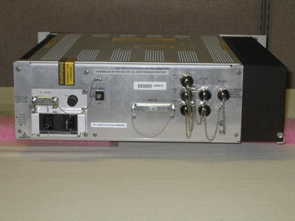
MIJMXU2000N-RFixed Satellite Tranceiver
General Dynamics Mission Systems
Click to zoom
Application Details
- Equipment Class
- TNB - Licensed Non-Broadcast Station Transmitter
- Date of Grant
- Apr 04, 1999
- Application Purpose
- Original Equipment
- Date of Application
- Feb 04, 1999
- Equipment Note
- Fixed Satellite Tranceiver
- Frequency Range
- 1616.00000000 - 1626.00000000
- Country
- United States
Documents & Files
Document Text
Text extracted from the exhibit documents filed with the FCC. Open a document above to read the original.
Users Manual
APPLICANT: MOTOROLA GSTG FCC ID: MIJMXU2000N-R DRAFT OF ADMINISTRATION MANUAL EXHIBIT 7A DRAFT COPY NOMAD MXU Administration Manual 3:33 PM 02/12/99 DRAFT COPY 1 ASTERISK INDICATES DATA REVISIONS WHICH IS NONMANDATORY REVDESCRIPTIONDATEAPPROVED FOR INFORMATION ONLY XAEngineering Red Line Control3 Feb 99KHS *APPLICATIONXB NEXT ASSYUSED ON SEE SEPARATE WIRE LIST YES NO X SEE SEPARATE PARTS LIST YES NO X PROJ. NO.DWN BYINTERPRET DRAWING IN ACCORDANCE 14114Ken SchmidtWITH STANDARDS LISTED IN DOD-STD-100. UNLESS OTHERWISE SPECIFIED: DOC CHK BY SCOTTSDALE, A Z 8 5252 - 1417 Space and Systems Technology Group DSGN CHK BY ALL DIMENSIONS ARE INCHES.CONTR NO. DWG IS END PROD. MXU NOMAD ADMINISTRATION MANUAL ISSUED TOLERANCES: 2 PLACE DEC ± N/AMATL APVD 3 PLACEMFG APVD DEC ± N/ASIZECAGE CODEDRAWING NO. ENGRG APVD A94990 HOLE DIA N/A CUST APVD ANGLE ± N/ANA SCALE NONE WT. NASHEET 1 OF DRAFT COPY NOMAD MXU Administration Manual 3:33 PM 02/12/99 DRAFT COPY 2 NOMAD MXU Configuration Manager (MCM) Software License Agreement (on the CDs) NOMAD MXU Application Software License Agreement Technical Support Numbers DRAFT COPY NOMAD MXU Administration Manual 3:33 PM 02/12/99 DRAFT COPY 3 Version Date Name Reason VersionDatenameReasonChange DRAFT COPY NOMAD MXU Administration Manual 3:33 PM 02/12/99 DRAFT COPY 4 1. TABLE OF CONTENTS 1INTRODUCTION................................................................................................................................. 7 1.1Purpose............................................................................................................................................ 7 1.2Acronyms and Definitions .............................................................................................................. 7 1.3Safety .............................................................................................................................................. 7 2NOMAD SYSTEM OVERVIEW ........................................................................................................ 9 2.1System Description ......................................................................................................................... 9 2.2NOMAD MXU Configuration Manager (MCM) ......................................................................... 10 2.2.1MCM Overview .................................................................................................................... 10 2.2.2MCM Features ...................................................................................................................... 11 2.2.2.1Main Screen ...................................................................................................................... 11 2.2.2.2Date Fields ........................................................................................................................ 11 2.2.2.3NOMAD MXU Location Information .............................................................................. 12 2.2.2.4NOMAD MXU Connection Data ..................................................................................... 12 2.2.2.5Nomad Airtime Recharge ................................................................................................. 13 2.2.2.6Security Configuration ...................................................................................................... 14 2.2.2.7Define Groups ................................................................................................................... 15 2.2.2.8Selecting a Group to Display ............................................................................................16 2.2.2.9Add NOMAD ISU Button ................................................................................................ 16 2.2.2.10NOMAD ISU Display Window .................................................................................... 17 2.2.2.11Changing Entries........................................................................................................... 17 2.2.2.12Menu Bar ...................................................................................................................... 18 2.2.2.12.1File Menu.................................................................................................................. 18 2.2.2.12.2Connect Menu........................................................................................................... 19 2.2.2.12.3Diagnostics Menu .....................................................................................................19 2.2.2.12.4Security Menu........................................................................................................... 20 2.2.2.12.5Support Menu ........................................................................................................... 21 2.2.2.13Display / File Options ................................................................................................... 21 2.3NOMAD Console ......................................................................................................................... 21 2.3.1Front Panel ............................................................................................................................ 22 2.3.2Back Panel ............................................................................................................................ 23 3INSTALLATION ................................................................................................................................ 25 3.1Overview....................................................................................................................................... 25 3.2Install NOMAD MXU Console ....................................................................................................26 3.3Install Admin and Monitors PCs.................................................................................................. 26 3.3.1PC Configurat…
Text truncated - open the document above for the full version.
Users Manual
APPLICANT: MOTOROLA GSTG FCC ID: MIJMXU2000N-R DRAFT OF INSTALLATION MANUAL EXHIBIT 7B DRAFT COPY NOMAD MXU Installation Manual 3:36 PM 02/12/99 DRAFT COPY 1 ASTERISK INDICATES DATA REVISIONS WHICH IS NONMANDATORY REVDESCRIPTIONDATEAPPROVED FOR INFORMATION ONLY XAEngineering Red Line Control3 Feb 99KHS *APPLICATIONXB NEXT ASSYUSED ON SEE SEPARATE WIRE LIST YES NO X SEE SEPARATE PARTS LIST YES NO X PROJ. NO.DWN BYINTERPRET DRAWING IN ACCORDANCE 14114Ken SchmidtWITH STANDARDS LISTED IN DOD-STD-100. UNLESS OTHERWISE SPECIFIED: DOC CHK BY SCOTTSDALE, A Z 8 5252 - 1417 Space and Systems Technology Group DSGN CHK BY ALL DIMENSIONS ARE INCHES.CONTR NO. DWG IS END PROD. NOMAD MXU INSTALLATION MANUAL ISSUED TOLERANCES: 2 PLACE DEC ± N/AMATL APVD 3 PLACEMFG APVD DEC ± N/ASIZECAGE CODEDRAWING NO. ENGRG APVD A94990 HOLE DIA N/A CUST APVD ANGLE ± N/ANA SCALE NONE WT. NASHEET 1 OF DRAFT COPY NOMAD MXU Installation Manual 3:36 PM 02/12/99 DRAFT COPY 2 PRE-INSTALLATION CHECKLIST Refer to Appendix “A” for the “NOMAD MXU Pre-Installation Checklist”. The checklist should have been completed before the NOMAD MXU was ordered, or at least before the MXU shipment arrived on site. The intent of the checklist is to prevent problems during the installation stages defined in this document. SERVICE INFORMATION Contact the Gateway for questions concerning the installation, initialization and operation of the NOMAD MXU System MANUAL REVISION HISTORY Version Date Name Reason VersionDatenameChange XA3/Feb/99KHSInitial draft copy, engineering release, Note: Copy sent to FCC XB DRAFT COPY NOMAD MXU Installation Manual 3:36 PM 02/12/99 DRAFT COPY 3 TABLE OF CONTENTS 1Introduction........................................................................................................................................... 4 1.1How To Install The NOMAD MXU System. ................................................................................. 4 1.2How To Use This Manual ............................................................................................................... 5 1.3Acronyms and Definitions .............................................................................................................. 6 2Safety...................................................................................................................................................... 7 2.1Safety Procedures and Precautions ................................................Error! Bookmark not defined. 2.1.1General Hazard Areas. ............................................................................................................ 7 3Description of Material Received ........................................................................................................ 9 3.1User Site, Material Received........................................................................................................... 9 3.1.1Console and Mounting Kit ...................................................................................................... 9 3.1.2Antenna Assembly and Mounting Kit..................................................................................... 9 3.1.3Interconnecting Cable Kits.................................................................................................... 10 3.1.4Manual and Monitor CD, Users Location ............................................................................. 10 3.2Administrative Site, Material Received ........................................................................................ 10 3.2.1Manuals and Administrative CD, Gateway Location............................................................ 10 4Installation ........................................................................................................................................... 11 4.1Console Installation....................................................................................................................... 11 4.2Antenna Installation ...................................................................................................................... 12 4.2.1Placement .............................................................................................................................. 12 4.2.2Installation............................................................................................................................. 13 4.3System Interconnections ............................................................................................................... 15 4.3.1Building Ground ................................................................................................................... 15 4.3.2Antenna Interconnections...................................................................................................... 15 4.3.3Power Connection ................................................................................................................. 18 4.3.4PSTN to MXU Inter-Connections......................................................................................... 18 5Checkout .............................................................................................................................................. 19 5.1Initial Power Up Checks ............................................................................................................... 19 5.2PSTN Check.................................................................................................................................. 20 5.3Monitor Station Check (Optional) ................................................................................................ 21 5.4Satellite Link Checks (Optional)................................................................................................... 21 5.5Request Initialization .................................................................................................................... 22 6Trouble Shooting Guidelines…
Text truncated - open the document above for the full version.
Attestation Statements
APPLICANT: MOTOROLA GSTG FCC ID: MIJMXU2000N-R STATEMENT OF CERTIFICATION The technical data supplied with this application, having been taken under my supervision is hereby duly certified. The MXU uses the same basic transceiver as a previously certified unit under FCC ID: IHDT6NE1 and some of that information has been represented in this filing. This is a statement of my qualifications: BSEE 1982 Northern Arizona University, Flagstaff, Arizona NARTE Certified EMC Engineer, 9 years 14 years experience in EMC Engineering design and test SIGNATURE: **Signed** NAME: Gil O. Estrella DATE: 02/5/98 POSITION: Sr Staff Engineer I hereby certify that the above application was prepared under my direction and that to the best of my knowledge and belief, the facts set forth in the application and accompanying technical data are true and correct. SIGNATURE: **Signed** NAME: Dwayne R. Awerkamp DATE:02/5/98 POSITION: EMC Department Manager EXHIBIT 1
Cover Letter(s)
Systems Solutions Group Mail Drop H 2550, 8201 E. McDowell, Scottsdale, AZ 85252 5 February 1999 CONFIDENTIALITY REQUEST CONTAINED WITHIN Federal Communications Commission Authorization and Evaluation Division 7435 Oakland Mills Road Columbia, Maryland 21046 Re: Application for MXU Certification – MIJMXU2000N-R Gentlemen: Motorola, Inc., Systems Solutions Group, 8201 E. McDowell Rd, Scottsdale, Arizona 85252 herein submits: Remittance Advice (FCC Form 159 – per US Mail with Fee Codes EFT and EBC, $610.00 VISA), Application for Equipment Authorization (FCC Form 731 – Electronic Filing), and Exhibits (Electronic Filing) for Certification of the MXU, Portable Satellite Transceiver, under FCC Rule Part 25, FCC ID: MIJMXU2000N-R. Motorola is also the manufacturer of this equipment. Although the Commission’s Rules do not presently include mobile earth terminals in the Equipment Authorization program, the Sunshine Notice for the Commission’s May 14, 1998, meeting indicates that the Commission will be proposing standards for approval of equipment used in the Global Mobile Personal Communications by Satellite service. The Commission will also be establishing an interim equipment approval program in order to begin implementation of the GMPCS-MoU Arrangements. This application should, therefore, be processed in accordance with that interim GMPCS equipment approval program. In addition to confidentiality for the entire application prior to grant (per 47CFR0.457(d)(1)(ii)), Motorola requests, pursuant to 47CFR0.459, post-grant confidentiality for identified sections of the filing material contained in this application with this material being withheld from public inspection following the grant of this authorization. This material includes Exhibit 5, Circuit Diagrams and Exhibit 6, Circuit Descriptions. Specifically, these exhibits contain information relating to circuit function and complexity that could be of benefit to competitors. This material contains Motorola’s trade secrets and confidential information which Motorola does not customarily release to the public and which, otherwise, is not generally available to the public. Please contact me by telephone at (602) 441-3725, by facsimile at (602) 441-3625, or by email at [email protected] if there are any further questions or additional information needed regarding the filing. Sincerely, **Signed** Gil Estrella EMC Engineer Motorola SSG
Cover Letter(s)
APPLICANT: MOTOROLA GSTG FCC ID: MIJMXU2000N-R LIST OF EXHIBITS EXHIBIT DESCRIPTION FCC REFERENCE __________________________________________________________________ 1 CERTIFICATION OF DATA 2.911 2 GENERAL INFORMATION PRODUCTION PLANS APPLICATION REFERENCES 2.1061 DATA SUBMITTAL PROCEDURE 2.947 SIMILAR APPLICATIONS 3 DESCRIPTION TECHNICAL CHARACTERISTICS 2.1033-C APPLICATION 5 CIRCUIT DIAGRAMS 2.1033-C-10 6 CIRCUIT DESCRIPTION INDEX 2.1033-C-10-13 6A MEANS FOR FREQUENCY STABILIZATION 6B MEANS FOR ATTENUATION OF SPURIOUS EMISSIONS 6C MEANS FOR LIMITING MODULATION 6D MEANS FOR ATTENUATION OF HIGHER AUDIO FREQUENCIES 6E MEANS FOR LIMITING POWER OUTPUT 6F DIGITAL MODULATION TECHNIQUES 7 INSTRUCTION MANUAL 2.1033 8 TRANSCEIVER ADJUSTMENTS 2.1033-C-9 9 MEASURED DATA (INDEX) 2.1033-C-14 9A RF OUTPUT MEASURED DATA 2.1046 9B OCCUPIED BANDWIDTH-GRAPH 2.1049 9C-1,2,3 FCC CONDUCTED SPURIOUS EMISSIONS-GRAPHS 2.1051 9D FCC RADIATED SPURIOUS EMISSIONS-GRAPHS 2.1053 9E FREQUENCY STABILITY VS TEMP-GRAPH 2.1055 9F FREQUENCY STABILITY VS VOLTAGE-GRAPH 2.1055 9G-1,2 TBR41 CONDUCTED SPURIOUS OUT-OF-BAND EMISSIONS-GRAPHS 9H TBR41 RADIATED SPURIOUS EMISSIONS-GRAPHS 9J-1,2,3,4 TBR41 IN-BAND CONDUCTED EMISSIONS 9K TBR41 EIRP DENSITY MEASUREMENT 10 IDENTIFICATION (NAMEPLATE) INFORMATION 2.1033-C-2-11 11-1,2,3,4 PHOTOGRAPHS 2.1033-C-12 12 MEASUREMENT TECHNIQUES
External Photos
APPLICANT: MOTOROLA GSTG FCC ID: MIJMXU2000N-R EXHIBIT 11-1 Enlarged view of panel section APPLICANT: MOTOROLA GSTG FCC ID: MIJMXU2000N-R EXHIBIT 11-2 Enlarged view of FCC ID placement area APPLICANT: MOTOROLA GSTG FCC ID: MIJMXU2000N-R EXHIBIT 11-3 (4) LBT FCC ID: IHDT6NE1 (4) LBT FCC ID: IHDT6NE1 APPLICANT: MOTOROLA GSTG FCC ID: MIJMXU2000N-R EXHIBIT 11-4
ID Label/Location Info
APPLICANT: MOTOROLA GSTG FCC ID: MIJMXU2000N-R EXHIBIT 10 FCC I D: MIJMXU2000N-R The Equipment ID label above is representative (in size and in showing the FCC Identifier as it will appear) of the label that is presently planned to appear on the equipment when in production. Its planned location is shown in Exhibit 11-2.
Operational Description
APPLICANT: MOTOROLA GSTG FCC ID: MIJMXU2000N-R EXHIBIT 2-1 GENERAL INFORMATION 1. Production Plans Quantity production is planned. 2. Application References---Pursuant 2.1061 Reference is made to the following Motorola “Application References on file with the Commission: None 3. Data Submittal Procedure: Data is supplied in accordance with Part 2, Sub-part J of the Commission’s rules. Standards used on measurements supplied are: ETSI TBR41 and section 47CFR25.202. 4. Similar to “Currently Certified Transmitter Type(s)” IHDT6NE1, which uses the same basic transceiver as this unit. 5. Report of measurements pertaining to types of emission, frequency range, maximum output power and modulation techniques. A. Types of emission The pertinent emission designator for the mobile satellite phone is 41K7Q7W, as explained in paragraph 6 of this exhibit. Actual measurements of Occupied Bandwidth are shown in Exhibit 9B. Spurious Emissions (Conducted and Radiated) are reported in Exhibits 9C, 9D (unique FCC requirements), 9H and 9J (European TBR41 standards). B. Frequency Range The frequency range of the equipment is in the band of 1616 MHz to 1626 MHz, in accordance with the Technical Basis for Regulation (TBR41) of Satellite Personal Communications Networks (S-PCN) for Mobile Earth Stations (MESs) in the 1.6/2.4 GHz bands. APPLICANT: MOTOROLA GSTG FCC ID: MIJMXU2000N-R EXHIBIT 2-2 Frequency Stability versus temperature and voltage measurements are shown in Exhibits 9E and 9F. This equipment uses Automatic Frequency Control (AFC) to lock within +/- 600 Hz of the received frequency from the Space Vehicle (SV). The mobile performs all frequency pre-correction for Doppler shifts. The system is designed to be tolerant of these frequency offsets. C. Maximum Output Power: Radio Frequency Output Power ranges from 0.1 to 0.6 Watts. The mobile maximum output power is achieved under closed loop control with the SV network. The mobile power will respond to commands from the SV network to change power levels as defined in the specifications. RF Output Power Measurements are shown in Exhibit 9A. D. Modulation Techniques Modulation is DEQPSK (Differentially Encoded Quadrature Phase Shift Keying) Exhibits 6C and 6D further discuss details of the modulating circuitry. Exhibit 6F discusses digital modulation techniques. 6. Determination of Emission Designator for the portable satellite transceiver (per Part 2-Subpart C of the commission’s rules) A. Emission, modulation and transmission characteristics (per section 2.201) a. First Symbol - Type of Modulation of the main carrier. The main carrier is pulsed in a TDMA format, utilizing Differentially Encoded Quadrature Phase-Shift Keying (DEQPSK) techniques. This corresponds to symbol Q, associated with the carrier being “angle modulated during the period of the pulse.” b. Second Symbol - nature of signal(s) modulating the main carrier. In-phase (I) and Quadrature (Q) modulating signals representing sampled, quantized voice or other audio information or data, modulates the main carrier. APPLICANT: MOTOROLA GSTG FCC ID: MIJMXU2000N-R EXHIBIT 2-3 This corresponds to symbol 7, derived from two channels “containing quantized or digital information” modulated in-phase and quadrature modulated. c. Third Symbol - Type of information to be transmitted. The information transmitted is a combination of data transmission (command data) and telephony (sample quantized voice or other audio signals). This corresponds to W, defined as “combinations of above” which would be the combination of the symbol D, “Data transmission, telemetry, telecommand”, and symbol E, “Telephony (including sound broadcasting)”. B. Bandwidths (per section 2.202) Bandwidth is primarily determined by a 96 tap FIR filter used to filter I and Q channel modulating signals and is consistent with a necessary bandwidth specification of 41.667 kHz. Converting this result, using the format indicated in paragraph 2.202(a), yields 41K7. The resulting complete emission designator is then 41K7Q7W .
Operational Description
APPLICANT: MOTOROLA GSTG FCC ID: MIJMXU2000N-R EXHIBIT 3 DESCRIPTION 1. Transmitter Technical Characteristics - Pursuant 2.1033 A. RF Power Output: Variable range from 0.1 to 0.6 Watts (by control of satellite network via closed loop power control). The transmitter duty cycle allows for bursted transmission every 8.28 ms out of 90 ms, or 9.2%, at a rate of 50 kbps, or 25 k symbols/sec. B. Frequency Range: 1616 MHz to 1626 MHz C. Frequency Stability: +/- 0.00015 % (1.5 ppm) D. Emissions: 41K7Q7W E. D.C. Voltage into the Final RF Amplifier: 7.5 Volts DC, nominal D.C. Current into the Final RF Amplifier: 0.404 Amps (time averaged current with a 9.2% duty cycle). 2. Transmitter Application A. Power Supply Available The transmitter is normally operated by means of 120/230 VAC, 50/60 Hz power. B. Antenna Available The transceiver is provided with a standard RF connection designed to interface with a 50 Ohm characteristic impedance. The radio transmitter is designed to be used with an external (permanent), Right-Hand Circularly Polarized (RCHP) antenna which incorporates a Quarifilar Helix main element. The antenna provides near hemispheric coverage and omni-directional gain pattern. C. Maximum Transmit Channel Capacity 240 Channels
Parts List/Tune Up Info
APPLICANT: MOTOROLA GSTG FCC ID: MIJMXU2000N-R EXHIBIT 8 TRANSCEIVER ADJUSTMENTS There are no user accessible adjustments or tuning in the MXU portable satellite transceiver. All necessary adjustments and tuning are performed during manufacture of the product. Any adjustments or tuning after service also require special equipment and cannot be performed by the user.
Test Report
APPLICANT: MOTOROLA GSTG FCC ID: MIJMXU2000N-R EXHIBIT 9 SUBMITTED MEASURED DATA INDEX EXHIBIT MEASUREMENT 9A RF OUTPUT MEASURED DATA 9B OCCUPIED BANDWIDTH-GRAPHS 9C-1,2,3 FCC CONDUCTED SPURIOUS EMISSIONS-GRAPHS 9D FCC RADIATED SPURIOUS EMISSIONS-GRAPHS 9E FREQUENCY STABILITY VS TEMP-GRAPH 9F FREQUENCY STABILITY VS VOLTAGE-GRAPH 9G-1,2 TBR41 CONDUCTED SPURIOUS EMISSIONS-GRAPHS 9H TBR41 RADIATED SPURIOUS EMISSIONS-GRAPHS 9I TBR41 CONDUCTED EMISSIONS CARRIER OFF 9J-1,2,3,4 TBR41 IN-BAND CONDUCTED EMISSIONS 9K TBR41 EIRP DENSITY MEASUREMENT APPLICANT: MOTOROLA GSTG FCC ID: MIJMXU2000N-R EXHIBIT 9A RF Power Output Data The RF power output was measured with the indicated voltage and current applied into the final RF amplifying device(s). The RF output, DC current and RF Input Power are all time-averaged values which reflect a 9.2 % (8.28 ms Tx bursts / 90 ms frame) transmit duty cycle characteristic of transceiver operation. • RF Output Power: 0.607 Watts • DC Voltage: 7.5 Volts • DC Current: 0.404 Amps • RF Input: 0.092 mW APPLICANT: MOTOROLA GSTG FCC ID: MIJMXU2000N-R EXHIBIT 9B BANDWIDTH MEASUREMENT DATA FOR TRANSMITTER TYPES Q7W DEVIATION OF THE CARRIER WITH QPSK MODULATION HORIZONTAL SCALE = 1 MHz/DIVISION VERTICAL SCALE = 10 dB/DIVISION RESOLUTION BANDWIDTH = 3 kHz POWER LEVEL = .6 W (Mean Output Power) MEASURED DATA: 1. Modulate the transmitter with QPSK modulation, using pseudo random data. Obtain image on spectrum analyzer. COMMENTS: A 3 kHz resolution bandwidth was used instead of the 4 kHz specified in 47 CFR 25.202. A correction factor was included in the limit for the bandwidth difference. APPLICANT: MOTOROLA GSTG FCC ID: MIJMXU2000N-R EXHIBIT 9C-1 TRANSMITTER CONDUCTED EMISSIONS, CHANNEL #3Carrier Power: 7 W max (+38.45 dBm), .645 W average (+28 dBm)Carrier Frequency: 1616 to 1626.5 MHz (240 Channels)Channels Tested: Channels #3, #120, and #238*All other Emissions greater than 20 dB below the spec were not reported*No observable signals in GPS/GNSS band (1559-1605 MHz @ -70dBW/MHz & -80dBW/700Hz) SSG EMC Group *Spectrum search performed from 30 MHz to 16.3 GHz (10X Carrier Frequency) 2/5/99 -90-80-70-60-50-40-30-20-10 0 1000 10000 100000 Frequency (MHz) Spurious Level (dBc) Spec Limit (7W) = -51.45 dBc (-14.25 dBm) 2nd Harmonic, -84 dBc 5th Harmonic, -76 dBc CARRIER1616.1 MHz 3232.2 8080.5 6th Harmonic, -81 dBc 9696.6 APPLICANT: MOTOROLA GSTG FCC ID: MIJMXU2000N-R EXHIBIT 9C-2 TRANSMITTER CONDUCTED EMISSIONS, CHANNEL #120Carrier Power: 7 W max (+38.45 dBm), .645 W average (+28 dBm)Carrier Frequency: 1616 to 1626.5 MHz (240 Channels)Channels Tested: Channels #3, #120, and #238*Emissions greater than 20 dB below the spec were not reported*No observable signals in GPS/GNSS band (1559-1605 MHz @ -70dBW/MHz & -80dBW/700Hz) SSG EMC Group *Spectrum search performed from 30 MHz to 16.3 GHz (10X Carrier Frequency) 2/5/99 -90-80-70-60-50-40-30-20-10 0 1000 10000 100000 Frequency (MHz) Spurious Level (dBc) Spec Limit (7W) = -51.45 dBc (-14.25 dBm) 2nd Harmonic, -85 dBc 5th Harmonic, -79 dBc CARRIER1620.9 MHz 3241.8 8104.9 6th Harmonic, -81 dBc 9725.9 APPLICANT: MOTOROLA GSTG FCC ID: MIJMXU2000N-R EXHIBIT 9C-3 TRANSMITTER CONDUCTED EMISSIONS, CHANNEL #238Carrier Power: 7 W max (+38.45 dBm), .645 W average (+28 dBm)Carrier Frequency: 1616 to 1626.5 MHz (240 Channels)Channels Tested: Channels #3, #120, and #238*Emissions greater than 20 dB below the spec were not reported*No observable signals in GPS/GNSS band (1559-1605 MHz @ -70dBW/MHz & -80dBW/700Hz) SSG EMC Group *Spectrum search performed from 30 MHz to 16.3 GHz (10X Carrier Frequency) 2/5/99 -90-80-70-60-50-40-30-20-10 0 1000 10000 100000 Frequency (MHz) Spurious Level (dBc) Spec Limit (7W) = -51.45 dBc (-14.25 dBm) 2nd Harmonic, -84 dBc 5th Harmonic, -78 dBc CARRIER1625.9 MHz 3251.8 8129.5 6th Harmonic, -82 dBc 9755.4 APPLICANT: MOTOROLA GSTG FCC ID: MIJMXU2000N-R EXHIBIT 9D TRANSMITTER RADIATED EMISSIONS, MAX LEVELS OF CHANNELS #3, 120, 238Carrier Power: 7 W max (+38.45 dBm), .645 W average (+28 dBm)Carrier Frequency: 1616 to 1626.5 MHz (240 Channels)Channels Tested: Channels #3, #120, and #238*Emissions greater than 20 dB below the spec were not reported SSG EMC Group *Spectrum search performed from 30 MHz to 16.3 GHz (10X Carrier Frequency) 2/5/99 -100 -90-80-70-60-50-40-30-20-10 0 1000 10000 100000 Frequency (MHz) Spurious Level (dBc) Spec Limit (7W) = -51.45 dBc (-14.25 dBm) CARRIER 5th Harmonic, -73 dBc 4th Harmonic, -76 dBc 3rd Harmonic, -78 dBc 4848 6464 8080 APPLICANT: MOTOROLA GSTG FCC ID: MIJMXU2000N-R EXHIBIT 9E Transmitter Frequency Stability over Temperature -1.00 -0.80 -0.60 -0.40 -0.20 0.00 0.20 0.40 0.60 0.80 1.00 -40 -30 -20 -10 0 10 20 30 40 50 60 70 Temperature (C) 1 ppm of Transmitter Carrier Frequency = 1620.979 Hz Spec. Limit: +/- 1.5ppm Date: 9/15/98 APPLICANT: MOTOROLA GSTG FCC ID: MIJMXU2000N-R EXHIBIT 9F Transmitter Frequency Stability vs. Supply Voltage -1.0 -0.8 -0.6 -0.4 -0.2 0.0 0.2 0.4 0.6 0.8 1.0 80 85 90 95 100 105 110 115 120 Percentage of Nominal Supply Voltage (%) 4.4 V5.0 V 3.9 V 1 ppm of Transmitter Carrier Frequency = 1620.979 Hz Spec. Limit: +/- 1.5ppm Date: 9/15/98 APPLICANT: MOTOROLA GSTG FCC ID: MIJMXU2000N-R EXHIBIT 9G-1 TBR 041 OUT OF BAND CONDUCTED EMISSIONS, CHANNEL #3Carrier Power: 7 W max (+38.45 dBm), .645 W average (+28 dBm)Carrier Frequency: 1616 to 1626.5 MHz (240 Channels)Channels Tested: #3 and #238* No observable signals in GPS/GNSS Band (1559-1605 MHz @ -70dBW/MHz), MSS> 6 dB below spec *Emissions greater than 20 dB below the spec were not reported SSG EMC Group *Spectrum search performed from 100 kHz to 12.75 GHz 2/5/99 -50-45-40-35-30-25-20 1000 10000 100000 Frequency (MHz) Spurious Level (dBm) TBR 041 Spec Limit = -30 dBm 2nd Harmonic, -38 dBm 3rd Harmonic, -37 dBm 3232 4848 6th Harmonic, -34 dBm 7th Harmonic, -37 dBm 5th Harmonic, -35 dBm 4th Harmonic, -35 dBm 6464 8080 9696 11312 APPLICANT: MOTOROLA GSTG FCC ID: MIJMXU2000N-R EXHIBIT 9G-2 TBR 041 OUT OF BAND CONDUCTED EMISS…
Text truncated - open the document above for the full version.
Test Report
APPLICANT: MOTOROLA GSTG FCC ID: MIJMXU2000N-R EXHIBIT 12-1 MEASUREMENT TECHNIQUES 2.991 Measurements Required : Conducted Spurious and Harmonic Emissions at Antenna Terminals Graph Attached EXHIBIT NO. s 9C-1,2,3 Definition - (as used herein) Spurious radiation is the radio frequency voltages or power generated within the equipment and appearing at the equipment's output terminals when properly loaded with its characteristic non-radiating artificial load. Minimum Standard – The mean power of conducted spurious and harmonic emissions shall be attenuated below the mean output power of the transmitter by: Frequency Offset Attenuation (per 4 kHz) 20.833 to 41.667 kHz 25 dBc 41.667 to 104.16 kHz 35 dBc >104.16 kHz 43 + 10log (Tx Pwr) In the range of frequencies between 1559 to 1605 MHz, emissions shall not exceed an EIRP density level of -70 dBW/MHz (-40 dBm/MHz) averaged over any 20 ms period and –80 dBW (-50 dBm) for any discrete (…
Text truncated - open the document above for the full version.
Contact Information
Applicant
Gil O. Estrella(EMC Engineer)
Technical Contact
Motorola CGISSGil O Estrella
[email protected]602-441-3725
8201 E. McDowell Rd · Scottsdale, Arizona · United States
Technical Specifications
| # | Rule Parts | Frequency Range | Power Output | Emission | Tolerance |
|---|---|---|---|---|---|
| 1 | 25 | 1.62 GHz - 1.63 GHz | 600.00 mW | 41K7Q7W | 1.0000000000 ppm |
Other Applications from General Dynamics Mission Systems
MIJCM350V2
Aug 18, 2013CM-350 (V2) Air Traffic Control VHF Digital Transmitter (VDT)
Equipment Class
TNB - Licensed Non-Broadcast Station Transmitter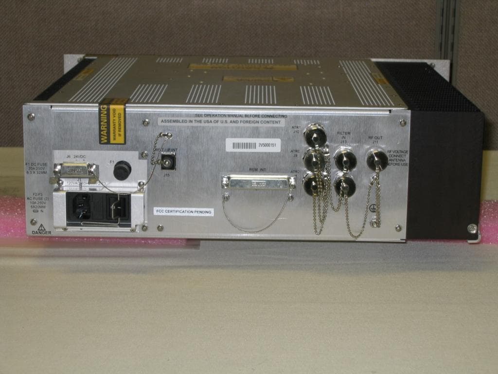
MIJCM300V2
Aug 18, 2013CM-300 (V2) Air Traffic Control VHF Digital Transmitter (VDT)
Equipment Class
TNB - Licensed Non-Broadcast Station Transmitter
MIJPNR-1000
May 08, 2012PathMaker Network Radio
Equipment Class
DTS - Digital Transmission System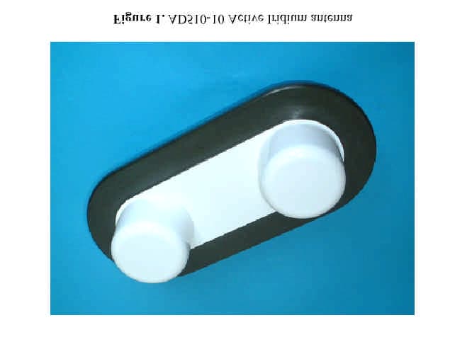
MIJAD510
May 18, 2003Iridium Satellite Transceiver Active Antenna
Equipment Class
AMP - Amplifier
MIJZEPCPE-USB-01
Mar 21, 2000Customer Premise Equipment - LMDS
Equipment Class
TNB - Licensed Non-Broadcast Station Transmitter