MMA1001Mobile CB Radio
Midland Radio Corporation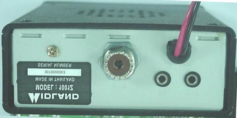
Click to zoom
Application Details
- Equipment Class
- TNB - Licensed Non-Broadcast Station Transmitter
- Date of Grant
- Oct 20, 2003
- Application Purpose
- Original Equipment
- Date of Application
- Oct 20, 2003
- Equipment Note
- Mobile CB Radio
- Frequency Range
- 26.96500000 - 27.40500000
- Company
- Midland Radio Corporation
- Country
- United States
Documents & Files
Document Text
Text extracted from the exhibit documents filed with the FCC. Open a document above to read the original.
Users Manual
Midland Model 1001Z Owners Guide 40 Channel mobile citizens band transceiver 2 40 Channel mobile citizens band transceiver........................ 1 How to install your Midland mobile CB.................................. 3 Installation and operating accessories furnished with your Midland CB: ................................................................................................... 3 Where to locate your CB transceiver................................................ 3 Mechanical mounting. ...................................................................... 4 Power wiring ( negative ground only). .............................................. 4 Installation of microphone hanger. ................................................... 5 Antenna: ................................................................................... 6 How to select, position install and tune the right one for you. .......... 6 Antenna installation. ......................................................................... 7 Tuning your antenna. ....................................................................... 7 Factors affecting CB range ..................................................... 7 Noise:........................................................................................ 7 Midland MODEL 1001Z CB Operating controls ..................... 8 FRONT PANEL CONTROLS .................................................... 8 BACK PANEL ......................................................................... 10 HOW TO OPERATE YOUR TRANSCEIVER .......................... 10 TECHNICAL SPECIFICATIONS ............................................. 10 GENERAL ...................................................................................... 10 TRANSMITTER .............................................................................. 11 SERVICE................................................................................. 11 LIMITED WARRANTY............................................................. 12 Midland MODEL 1001Z 40 Channel mobile citizens band transceiver For your protection, the space below is provided for you to record the Serial Number of this product, which is located on the rear of the radio. After recording this number, keep this record for future reference along with the sales receipt. The sales receipt is needed should your radio ever need service. FCC I.D. MMA1001 Serial Number:____________________ 3 Welcome to the world of Midland electronics Congratulations. You have just purchased a state of the art mobile CB radio. In the years ahead, you can expect to realize-time and again the real reasons and meaning of the front running position Midland holds among CB users everywhere. You will come to know that Midland power is more than just a slogan, but the heading of long list of hearable, seeable benefits. As your Midland CB experience unfolds and grows we hope you will remember that CB is only one kind of electronic excellence available under the Midland name. Your 40 channel CB represents the state of the art in high tech engineering. The unit incorporates microprocessor controlled PLL circuitry for precise tuning. How to install your Midland mobile CB This transceiver may be installed in any 12-volt negative ground- system car or truck. Most current U.S. and foreign vehicles use a negative system, but some older models and some newer large trucks may have a positive ground. Check the requirements for your vehicle before you begin installation. Generally, you have a negative-ground system if the minus ( - ) battery terminal is connected to the motor block. Contact your dealer in the event you are unable to determine your vehicle’s polarity system. Installation and operating accessories furnished with your Midland CB: 1. Easy removal mounting bracket system. 2. Microphone bracket system. 3. All main-unit and microphone mounting hardware needed for normal installation. 4. Plug-in microphone with coil cord. 5. FCC part 95, Subpart D. 6. Owner’s Manual. Where to locate your CB transceiver. Your new Midland CB is designed to be installed under the dash or vertically on a console of your vehicle. 4 Safety and convenience are the primary considerations in deciding exactly where to locate your radio. Caution: Be sure that the unit is located so that it does not interfere with the driver, supplemental restraint systems (air bags), or impair access to any controls. Connecting cables must be routed and secured in such a manner as not to interfere with the operation of the brake, accelerator or other controls. Interference from either the unit or connecting cables may contribute to the loss of control of the vehicle. Mechanical mounting. Step 1: Heeding the caution, use the mounting bracket as a template for marking the location of screw holes under the dash. Use an awl, nail or other sharp pointed object to mark the hole locations. Step 2: Drill a 1/8” hole for each screw hole in the mounting bracket. Attach the bracket to the dash with the Phillips head sheet metal screws provided. , Extreme care should be exercised when drilling into the dash to avoid damage to under-dash electronic ignition, cruise control, instrument and / or accessory wiring. Step 3: Position the main unit between the bracket arms in line with the retention knobs. Set the angle for optimum operating comfort and accessibility. Step 4 Tighten the retention knobs Power wiring ( negative ground only). Step 1: If you have not determined whether your vehicle has a negative or positive ground, do so now. Then disconnect the negative lead from the battery to prevent short circuits that can occur during wiring. Do not connect this transceiver to positive ground electrical systems. Step 2: With negative ground A.connect the positive (RED WIRE) the one with in-line fuse holder to either the ( a ) fuse block, ( b ) cigarette lighter, or ( c ) directly to the positive post on your battery. 5 Usually, the fuse block is the most conv…
Text truncated - open the document above for the full version.
External Photos
Midland Radio Corporation FCC ID: MMA1001 APPENDIX C - EUT PHOTOGRAPHS Chassis - Top View Chassis – Right Side View Midland Radio Corporation FCC ID: MMA1001 Chassis – Left Side View Chassis - Front View Midland Radio Corporation FCC ID: MMA1001 Chassis – Rear View
ID Label/Location Info
APPENDIX A - FCC ID LABELING AND LOCATION Proposed FCC ID Labeling Proposed FCC ID Location Rear Side of EUT / Proposed Label Location FCC ID: MMA1001
Internal Photos
Midland Radio Corporation FCC ID: MMA1001 EUT – PCB Front View EUT – PCB Back View Midland Radio Corporation FCC ID: MMA1001 EUT – SubPCB Front View EUT – SubPCB Back View
Operational Description
CIRCUIT DESCRIPTION INTRODUCTION THE FREQUENCIES FOR TRANSMITTER AND RECEIVER LOCAL FREQUENCIES ARE ALL DRIVEN FROM A SINGLE 10240MHz CRYSTAL (X1) BY MEANS OF A PHASE LOCKED LOOP. THE FIRST LOCAL OSCILLATOR FREQUENCIES ARE 16.27MHz(CH.1) TO 16.71MHz(CH. 40) FOR RECEIVER. THE SECOND LOCAL FREQUENCY IS FIXED AT 10.240MHz(X1) TO GENERATE SECOND IF 455 KHz . DURING TRANSMIT, THE VCO OF THE PLL OPERATES 13.4825MHz TO 13.7025MHz. TO PLL IC PIN 12 Q603,L4,D601 VCO Q601 BUFFER AMP RX LOCAL FREQUENCY : 16.27MHz(CH.1) TO 16.71MHz(CH. 40) TX FREQUENCY : 13.4825MHz TO 13.7025MHz THE VCO OPERATING FREQUENCY FOR THE RECEIVER IS 16.27MHz (CH. 1) TO 16.71MHz (CH. 40) AS THE FIRST LOCAL OSCILLATOR, INJECTED THROUGH THE BUFFER AMP Q601 INTO THE FIRST TR MIXER Q103. DESCRIPTIONS OF EACH BLOCK INTRODUCTION THE SYNTHESIZER IS IMPLEMENTED WITH THE FOLLOWING COMPONENTS : PLL IC(IC1), CRYSTAL(X1) VCO, VARI_CAP DIODE(D601) THE IC1 IS A BIPOLA_LSI THAT INCLUDES PRESCALLER, THE Q603, Q602, L4, C606, D601, C608, C609 ARE CLAP OSCILLATOR CIRCUIT TO OPERATE AS A VCO OF THE IC1. THE Q602 IS A SWITCHING DIODE TO CONNECT OR DISCONNECT THE TUNING CAPACITOR IN THE VCO OSCILLATOR TANK CIRCUIT FOR TRANSMITTER OR RECEIVER. THE Q601 WORKS AS A BUFFER AMP FOR RX LOCAL FREQUENCIES AND TX CARRIER GENERATING FREQUENCIES. REFERENCE FREQUENCY (CRYSTAL) THE CRYSTAL, X1(10.240MHZ) AND OTHER COMPONENTS AS PIN.9,10 OF IC1 CAN MAKE A REFERENCE FREQUENCY OSCILLATOR WITH INTERNAL AMPLIFIER. THIS SET IS USED EXTERNAL CLOCK SOURCE BY THE CRYSTAL. THE REF_FREQUENCY(10.240MHz) IS ADJUSTED BY CT1 EXACTLY. VCO THE Q603 AND SURROUNDING PARTS ARE CONSISTING A CLAPP OSCILLATOR WORKS AS A VCO OF IC1 WITH APPROPRIATE CONTROL VOLTAGE ON D601. THE VCO CAN BE OSCILLATE OVER THE REQUIRES RANGE OF 13.4825MHz TO 16.71MHz . PROGRAMMABLE DIVIDER AND ITS CONTROL THE PROGRAMMABLE INPUTS FOR EACH CHANNELS ARE SETTED IC INSIDE. THE IC1 OUTPUT IS FED TO THE PHASE DETECTOR FOR COMPARING WITH THE 2.5KHZ REFERENCE FREQUENCY INSIDE. PHASE DETECTOR AND VCO CONTROL THE PHASE DETECTOR IS A DIGITAL PHASE COMPARATOR WHICH COMPARES THE PHASE OF THE REFERENCE SIGNAL WITH PROGRAMMABLE DIVIDER OUTPUT SQUARE WAVES AND DEVELOPS A SERIES OF PULSE WHOSE DC LEVEL DEPENDS ON THE PHASE ERROR OF EACH SIGNAL. THE PHASE DETECTOR PULSE OUTPUT IS FED TO AN ACTIVE LOW PASS FILTER, AND FED TO VARI_CAP D601 CONTROL THE VCO FREQUENCY. TRANSMITTER / RECEIVER BUFFER AMP OUTPUT SIGNAL OF Q603 IS FED INTO THE BUFFER AMP Q601 TO INCREASE THE STRENGTH OF TX CARRIER FREQUENCY AND 1ST LOCAL FREQUENCIES. SWITCHING OF TUNING CAPACITOR IN VCO THE VCO CIRCUIT MUST USE WITH A WIDE RANGE OF FREQUENCIES 13.4825MHz TO 16.71MHz FOR TRANSMITTER AND 16.27MHz(CH.1) TO 16.71MHz MHz FOR RECEIVER. TO COMPLY ABOVE RANGE OF VCO, THE TUNING CAPACITANCE SHOULD SWITCHED FOR TRANSMISSION OR RECEPTION. THE TUNING CIRCUIT CONSISTS WITH C609, Q602 WHEN THE VCO IS WORKING AS A RECEIVER, WHEN TRANSMITTING MODE, C609, Q602 BECOMES TURN ON. WHEN RECEIVING MODE, C609, Q602 BECOMES OFF, L4 AND THE D601 CAPACITANCE OF MAKE TUNING FUNCTION. RECEIVER LOCAL OSCILLATOR OUTPUTS 1ST MIXER : THE OUTPUT SINGLES OF Q601 IS INJECTED TO THE SOURCES OF 1ST MIXER Q103 IN THE 1ST IF MIXER SECTION. 2ND MIXER : THE OUTPUT OF 10.240MHz OSCILLATOR CIRCUIT WITH X1 IS INJECTED INTO THE Q201. INCOMING IF SIGNAL AND 10.695MHz SIGNAL ARE MIXED INSIDE THE Q201 TO EXTRACT 2ND IF SIGNAL 455 KHz . AM SIGNAL ARE RECEIVED WITH ENVELOPE DETECTOR. FREQUENCY STABILITY LET : Fo=CRYSTAL OSCILLATOR FREQUENCY Fr=PHASE DETECTOR REFERENCE FREQUENCY Fvco=VCO FREQUENCY Ft=TRANSMIT FREQUENCY THEN : Fr=Fo/2500 AND UNDER LOCKED CONDITIONS : Fr=Fvco/N WHERE, "N" IS THE DIVIDE RATIO OF PROGRAMMABLE DIVIDER. THEN : Fvco=N*Fr FROM WHICH IT CAN BE SEEN, THE PERCENTAGE ERROR IN THE SAME AS THE PERCENTAGE ERROR IN Fo. THE STABILITY OF THE CRYSTAL OSCILLATOR IS DETERMINED IN Ft IS THE SAME AS THE PERCENTAGE ERROR IN Fo. THE HAVING PASSIVE COMPONENTS OF THE OSCILLATOR. THE CHOICE OF CRYSTAL AND COMPONENTS IS SUCH THAT THE REQUIRES FREQUENCY STABILITY IS MAINTAINED OVER THE REQUIRED VOLTAGE AND TEMPERATURE RANGE. DESCRIPTION OF OTHER CIRCUITS TRANSMITTER RF AMPLIFICATION THE OUTPUT OF BUFFER AMP Q11 IS FED THROUGH TUNING C75,L5,L6 TO THE BASE OF PRE DRIVER AMP Q12. THE PRE DRIVER AMP OUTPUT SIGNAL FED THROUGH TO DRIVER AMP(Q13), FED THROUGH TO POWER AMP(Q14) TO THE ANTENNA. CIRCUIT FOR SUPPRESSION OF SPURIOUS RADIATION THE TUNING CIRCUIT BETWEEN THE OUTPUT OF FINAL AMP Q14 AND ANTENNA, 3 STAGE "LPF TYPE" NETWORK L802, L803, L804, C802, C803, C805, C7 SERVES AS A SPURIOUS RADIATION SUPPRESSOR. THIS NETWORK ALSO SPURIOUS RADIATION SUPPRESSOR.(OVER THEN 60DBC) THIS NETWORK ALSO SERVES TO MATCH THE IMPEDANCE BETWEEN TX POWER TR Q14 AND ANTENNA. MAXIMUM MODULATION CONTROL MODULATION SIGNALS ARE FILTERED WITH RC NETWORK AND GOES TO THE AUDIO_AMP IC(IC2) TO MAKE NOMINAL SIGNAL LEVEL TO ACHIEVE WANTED MODULATION. TO CONTROL INCOMING AUDIO SIGNAL BY ALC CIRCUIT. THE ALC ARE Q9,D8,RV2, THAT’S CIRCUIT CONTROL MAXIMUM MODULATION CAPABILITY AND MAXIMUM MODULATION LIMITTING. RECEIVER (1) RF AMP Q102 AMPLIFY RF SIGNAL FROM ANTENNA, AND THEN THE AMPLIFIED RF SIGNAL IS FED THROUGH MIXER(Q103) TO THE BASE OF MIXER Q103, ALSO VCO SOURCE'S FREQUENCY LOWER 10.695MHz THAN THE FREQUENCY OF EACH CHANNEL IS SUPPLIED TO MIXER. (2) THE SOURCE OF 10.695MHz FREQUENCY IS FED THROUGH CF-1 TO 2’ND MIXER Q201. (3) THE 455 KHZ FREQUENCY SIGNAL IS PRODUCED FROM Q201 BY MIXING THE OUTPUT SOURCE OF CF-1 10.695MHz FILTER AND THE SOURCE OF 10.24MHz FREQUENCY FROM CRYSTAL OSCILLATOR X1. (4) THE Q202 IS IF AMP, AND D3 IS DETECT DIODE. AUDIO SIGNAL RECOVER BY THAT DIODE. THE AUDIO SIGNAL IS FED THROUGH C4 TO AUDIO POWER AMP(IC2) FOR DRIVING SPEAKER.
Parts List/Tune Up Info
SEQ LEVPART-NO.NAME & DESCRIPTIONQ'TY 1 2533-55C-ACOVER ASS'Y1 3 420-128-6SPEAKER 8 OHM 1W 66MM1 3 611-086(+)MACHINE SCREW(FH)2.6X4 ZN-PLAT4 3 623-265(+)TAPPING SCREW(BH)3X6-2S ZN-PLAT3 3 633-170(+)TAP TITE SCREW BH3X8 BLK8 3 717-290COVER BOTTOM ABS 94HB BLK1 3 717-296COVER UPPER ABS BLK1 3 730-176-AHOLDER(SPK MTG) EGI US COATING T13 3 801-815E.S.C ABS 94H B1 3 814-361-AWINDOW ACRYL1 3 826-143KNOB VOL ABS 94HB BLK2 3 826-144KNOB CH ABS 94HB BLK1 3 826-333KNOB SLIDE ABS94HB L380-90012 3 901-032FELT 6X110XT0.5 FELT STIC.4 3 901-226FELT &65XT0.3 FELT BL K1 3 907-416DOUBLE TAPE 3M T0.11 3 95B-142LABEL NAME POLYESTER 80X481 2 2533-55C-01CRYSTAL ASS'Y1 3 260-863-3XCRYSTAL HC49U 10.240M -30 30PM 17P FUND1 3 2533-55F-BFRONT BODY ASS' Y1 3 204-010-1TRANSISTOR 2SC2078(E)1 3 222-006-4I.C KIA7217AP1 3 420-705-1ZJACK DC TC38-078-012 3 421-046-7CONNECTOR CH-239(A) SW-12291 3 427-179-4WIRE BRAID0.12 3 440-020-4MICA 0.1T:15X13 MICA FOR T R2 3 504-734-ZPOWER CORD ASS'Y UL 1015 #20 150MM FUSE H O1 3 613-332(+)MACHINE SCREW(BH)3X10 ZN-PLAT2 3 621-159(+)TAPPING SCREW(BH)2.6X8-1S ZN-PLAT2 3 623-265(+)TAPPING SCREW(BH)3X6-2S ZN-PLAT4 3 651-024NUT SS41 M3-1S ZN-PLA T2 3 662-305WASHER (SPRING) M3 ZN-PLA T2 3 702-005-ABODY MAIN EGI T1.0 U.S COATING1 3 730-478HOLDER(ANT MTG) SPC 42X40XT0.5 NI-PLAT1 3 750-039-ACORD STOPPER P.P BL K1 3 760-704HEAT SINK(IC MTG) ALP 30X18XT21 3 761-576HEAT SINK ALP3 T21 3 853-105BUSHING NYLON66+GLASS1 4 2533-55M-AMIC ASS' Y1 3 130-A17-6XCHIP CERAMIC 0.001UF CL21B102KBNC 50 V1 3 420-205-9WMIC CONDENSER YCM9765-W-0051 3 420-349-6ZCURD CURLED 3CON 1SH 300MM BLK(KSK-23051 3 421-038-0CONNECTOR PLUG SW-14611 Part list Midland 1001 Z 3 432-058-3YPUSH SWITCH SKPS-2210C1 3 600-092SCREW(SECURING) ABS94HB M6X10(P=1 )2 3 621-089(+)TAPPING SCREW(PH)2.6X12-2S NI-PLAT4 3 621-159(+)TAPPING SCREW(BH)2.6X8-1S ZN-PLAT3 3 623-663(+)TAPPING SCREW(BH)3X10⁻²S NI-PLAT2 3 625-007(+)TAPPING SCREW(TH)5X12-1S ZN-PLAT3 3 642-026(+)WOOD SCREW (R+FH)2.7X14 NI-PLAT1 3 660-138WASHER RUBB.&7X&25XT1.5 BLK2 3 664-320WASHER(LOCK"B"TYPE) M3 NI-PLAT2 3 664-518WASHER(LOCK"B"TYPE) M5 ZN-PLAT3 3 710-408-AAUPPER COVER(MIC) ABS 94HB BL K1 3 710-418-ABOTTOM COVER (MIC) ABS 94HB BLK1 3 720-050BRACKET(MIC MTG) SPC 60X35XT11 3 720-916BRACKET(SET MTG) SPC 30X235XT1.5 BLK-PAINT 1 3 730-024-BHOLDER(MIC) PC BLK1 3 740-390LEVER(MIC) ABS SILK BLK1 3 780-214NAME PLATE(MIC) ALP3 16X47XT0.41 3 795-955NAME PLATE(MIC) PVC 23.9X12.8XT0.4 CLEAR1 3 830-122BEZEL ABS BL K1 3 830-480GRILL CAP(MIC) ABS BLK1 3 870-036WIRE CLAMP (CORD) NYLON1 3 894-674CUSHION &22XT4 SPONGE STICKE R1 3 896-069RUBBER RUBBER1 3 900-212FELT 34X36XT0.3 FELT1 3 91B-649BOX MIC SW2E 221(W)X70(D)X54(H )1 3 921-010-EPOLYBAG P.E 100X100XT0.052 3 921-020-EPOLYBAG P.E 100X200XT0.051 3 940-092CARD WARNING POS & NEGA1 5 2533-55M-PAMAIN PCB AUTO ASS' Y1 3 060-101-6ZCHIP RESISTOR 100 1/10W 5% T 201 24 3 060-102-7ZCHIP RESISTOR 1K 1/10W 5% T 201 26 3 060-103-8ZCHIP RESISTOR 10K 1/10W 5% T 20128 3 060-104-9ZCHIP RESISTOR 100K 1/10W 5% T 201 21 3 060-151-1ZCHIP RESISTOR 150 1/10W 5% T 201 27 3 060-152-2ZCHIP RESISTOR 1.5K 1/10W 5% T 201 22 3 060-153-3ZCHIP RESISTOR 15K 1/10W 5% T 20123 3 060-154-4ZCHIP RESISTOR 150K 1/10W 5% T 201 21 3 060-182-9ZCHIP RESISTOR 1.8K 1/10W 5% T 201 21 3 060-220-0ZCHIP RESISTOR 22 1/10W 5% T 20121 3 060-222-2ZCHIP RESISTOR 2.2K 1/10W 5% T 20123 3 060-223-3ZCHIP RESISTOR 22K 1/10W 5% T 201 24 060-000-3ZCHIP RESISTOR 0 1/10W 5% T 201 21 3 060-229-9ZCHIP RESISTOR 2.2 1/10W 5% T 201 21 3 060-272-7ZCHIP RESISTOR 2.7K 1/10W 5% T 201 21 3 060-273-8ZCHIP RESISTOR 27K 1/10W 5% T 201 22 3 060-274-9ZCHIP RESISTOR 270K 1/10W 5% T 20121 3 060-331-7ZCHIP RESISTOR 330 1/10W 5% T 20122 3 060-332-8ZCHIP RESISTOR 3.3K 1/10W 5% T 20121 3 060-333-9ZCHIP RESISTOR 33K 1/10W 5% T 201 21 3 060-391-1ZCHIP RESISTOR 390 1/10W 5% T 20121 3 060-470-9ZCHIP RESISTOR 47 1/10W 5% T 20122 3 060-471-0ZCHIP RESISTOR 470 1/10W 5% T 20123 3 060-472-1ZCHIP RESISTOR 4.7K 1/10W 5% T 20124 3 060-473-2ZCHIP RESISTOR 47K 1/10W 5% T 20121 3 060-561-8ZCHIP RESISTOR 560 1/10W 5% T 20121 3 060-680-2ZCHIP RESISTOR 68 1/10W 5% T 20121 3 100-101-9YELECT CAPACITOR 0.1UF 50V 20% 5X111 3 101-006-2YELECT CAPACITOR 1UF 50V 20% 5X11 2.5P T3 3 101-012-7ZELECT CAPACITOR 10UF 16V 20% 5X112 3 101-117-9ELECT CAPACITOR 1000UF 16V 20% 10X162 3 101-122-3ELECT CAPACITOR 100UF 16V 20% 6.3X112 3 101-122-3ELECT CAPACITOR 100UF 16V 20% 6.3X112 3 102-210-4ZELECT CAPACITOR 22UF 16V 20% 5X112 3 102-301-3ELECT CAPACITOR 220UF 35V 20% 8X121 3 103-303-0ZELECT CAPACITOR 3.3UF 50V 20% 5X11 2.5P T1 3 103-313-9YELECT CAPACITOR 33UF 16V 20% 5X113 3 104-707-7YELECT CAPACITOR 4.7UF 50V 20% 5X11 2.5PT1 3 104-771-4XELECT CAPACITOR 47UF 16V 20% 5X113 3 130-A17-6YCHIP CERAMIC 0.001UF GRM40 X7R102K 50V P T4 3 130-101-8YDISK CERAMIC 0.001UF F 102Z 50V2 3 130-102-9RDISK CERAMIC 0.01UF DD312B 103K 50V 7942 3 130-172-2YCHIP CERAMIC 0.01UF GRM40 X7R103K 50V PT 11 3 130-188-8Z AXIAL CERAMIC 0.01UF EP050Y103MN 16V1 3 130-424-0YCHIP CERAMIC 0.047UF GRM40 X7R473K 50V PT1 3 130-432-7YCHIP CERAMIC 0.0047UF GRM39 X7R472K 50V PT1 3 130-602-4YCHIP CERAMIC 0.0068UF GRM40 X7R682K 50V P T1 3 131-027-0YCHIP CERAMIC 100PF GRM40 COG101J 50V P T3 3 131-089-7YCHIP CERAMIC 1UF GRM40 Y5V105Z 16V P T1 3 131-511-0YCHIP CERAMIC 15PF GRM40 COG150J 50V PT2 3 131-529-7YCHIP CERAMIC 150PF GRM40 COG151J 50V P T1 3 131-811-1YCHIP CERAMIC 180PF GRM40 COG181J 50V P T1 3 132-012-1YCHIP CERAMIC 20PF GRM40 COG200J 50V P T1 3 132-220-2YCHIP CERAMIC 220PF GRM40 COG221J 50V PT1 3 132-235-6YCHIP CERAMIC 0.022UF GRM40 X7R223K 50V P T2 3 132-714-2YCHIP CERAMIC 27PF GRM40 COG270J 50V P T1 3 134-007-7YCHIP CERAMIC 4PF GRM40 COG040C 50V PT1 3 134-761-4YCHIP CERAMIC 470PF GRM40 COG471J 50V PT1 3 138-004-4YCHIP CERAMIC 8PF GRM40 COG080D 50V P T1 3 138-210-3YCHIP CERAMIC 82PF GRM40 COG820J 50V P T1 3 202-106-5TRANSISTOR KTA1504S Y5 3 202-112-0TRANSISTOR KTC3875S(GR)2 3 202-153-7TRANSISTOR KTC3880S Y3 3 241-063-6YDIODE ZENER 1N4733AST1 3 241-262-9DIODE ZENER 1N5239BST1 3 243-051-5DIODE SI CHIP…
Text truncated - open the document above for the full version.
RF Exposure Info
RF EXPOSURE According to §1.1307(b)(1), systems operating under the provisions of this section shall be operated in a manner that ensures that the public is not exposed to radio frequency energy level in excess of the Commission’s guidelines. According to §1.1310 and §2.1093 RF exposure is calculated. Limits for Maximum Permissive Exposure (MPE) (A) Limits for General Population/Uncontrolled Exposure Frequency Range (MHz) Electric Field Strength (V/m) Magnetic Field Strength (A/m) Power Density (mW/cm 2 ) Averaging Time (minute) Limits for General Population/Uncontrolled Exposure 0.3-1.346141.63*(100)30 1.34-30824/f2.19/f*(180/f 2 )30 30-30027.50.0730.230 300-1500//f/150030 1500-100,000//1.030 (B) Limits for Occupational/Controlled Exposures Frequency Range (MHz) Electric Field Strength (V/m) Magnetic Field Strength (A/m) Power Density (mW/cm 2 ) Averaging Time (minute) Limits for Occupational/Controlled Exposure 0.3-3.06141.63*(100)6 3.0-301842/f4.89/f*(900/f 2 )6 30-30061.40.1631.06 300-1500//f/3006 1500-100,000//56 f = frequency in MHz * = Plane-wave equivalent power density MPE Prediction Predication of MPE limit at a given distance Equation from page 18 of OET Bulletin 65, Edition 97-01 S = PG/4πR² Where: S = power density P = power input to antenna G = power gain of the antenna in the direction of interest relative to an isotropic radiator R = distance to the center of radiation of the antenna Maximum peak output power at antenna input terminal: 35.77 (dBm) Maximum peak output power at antenna input terminal: 3776 (mW) Prediction distance: 35 (cm) Predication frequency: 27 (MHz) MPE limit for uncontrolled exposure at prediction frequency: 0.25 (mW/cm^2) Antenna Gain (typical): 0 (dBi) Maximum antenna gain: 1 (numeric) Power density at predication frequency at 20 cm: 0.24 (mW/cm 2 ) Test Result The EUT is a mobile devise. The antenna’s power density level at 35 cm is 0.24 mW/cm², which is below the uncontrolled exposure limit of 0.25mW/cm² at 27 MHz
Test Report
Note: This test report is specially limited to the above client company and product model. It may not be duplicated without prior written consent of Bay Area Compliance Laboratory Corporation. This report must not be used by the client to claim product endorsement by NVLAP or any agency of the U.S. Government. FCC PART 95 EMI MEASUREMENT AND TEST REPORT For Midland Radio Corporation 1120 Clay Street North Kansas City, MO 64116 FCC ID: MMA1001 2003-09-15 This Report Concerns: Original Report Equipment Type: MOBILE CB RADIO Test Engineer: Ling Zhang / Report Number: R0308113 Test Date: 2003-09-03 Reviewed By: Hans Mellberg / Prepared By: Bay Area Compliance Laboratory Corporation 230 Commercial Street Sunnyvale, CA 94085 Tel: (408) 732-9162 Fax: (408) 732 9164 Midland Radio Corporation FCC ID: MMA1001 Report # R0308113RptFCC Part 95 Test ReportPage 2 of 28 TABLE OF CONTENTS 1 - GENERAL INFORMATION.................................................................................................................................................4 1.1 PRODUCT DESCRIPTION FOR EQUIPMENT UNDER TEST (EUT).........................................................................................4 1.2 OBJECTIVE................................................................................................................................................................................4 1.3 RELATED GRANT/SUBMISSION..............................................................................................................................................4 1.4 TEST METHODOLOGY.............................................................................................................................................................4 1.5 TEST FACILITY.........................................................................................................................................................................4 2 - SYSTEM TEST CONFIGURATION..................................................................................................................................6 2.1 JUSTIFICATION.........................................................................................................................................................................6 2.2 EUT TEST CONFIGURATION..................................................................................................................................................6 2.3 SPECIAL ACCESSORIES............................................................................................................................................................6 2.4 SCHEMATICS / BLOCK DIAGRAM..........................................................................................................................................6 2.5 EQUIPMENT MODIFICATIONS.................................................................................................................................................6 2.6 CONFIGURATION OF TEST SYSTEM.......................................................................................................................................7 2.7 TEST SETUP BLOCK DIAGRAM..............................................................................................................................................7 3 - REQUIREMENTS OF PROVISIONS................................................................................................................................8 3.1 TEST SUMMARY.......................................................................................................................................................................8 3.2 LABELING REQUIREMENT......................................................................................................................................................8 4 – CONDUCTED OUTPUT POWER......................................................................................................................................9 4.1 PROVISION APPLICABLE.........................................................................................................................................................9 4.2 TEST PROCEDURE....................................................................................................................................................................9 4.3 TEST EQUIPMENT.....................................................................................................................................................................9 4.4 TEST RESULTS..........................................................................................................................................................................9 5 - MODULATION CHARACTERISTICS...........................................................................................................................11 5.1 PROVISION APPLICABLE.......................................................................................................................................................11 5.2 TEST PROCEDURE..................................................................................................................................................................11 5.3 TEST EQUIPMENT..................................................................................................................................................................12 5.4 TEST RESULTS........................................................................................................................................................................12 6 - OCCUPIED BANDWIDTH OF EMISSION...................................................................................................................17 6.1 PROVISION APPLICABLE.......................................................................................................................................................17 6.2 TEST PROCEDURE...........................…
Text truncated - open the document above for the full version.
Test Report
Note: This test report is specially limited to the above client company and product model. It may not be duplicated without prior written consent of Bay Area Compliance Laboratory Corporation. This report must not be used by the client to claim product endorsement by NVLAP or any agency of the U.S. Government. FCC PART 95 EMI MEASUREMENT AND TEST REPORT For Midland Radio Corporation 1120 Clay Street North Kansas City, MO 64116 FCC ID: MMA1001 2003-09-15 This Report Concerns: Original Report Equipment Type: MOBILE CB RADIO Test Engineer: Ling Zhang / Report Number: R0308113 Test Date: 2003-09-03 Reviewed By: Hans Mellberg / Prepared By: Bay Area Compliance Laboratory Corporation 230 Commercial Street Sunnyvale, CA 94085 Tel: (408) 732-9162 Fax: (408) 732 9164 Midland Radio Corporation FCC ID: MMA1001 Report # R0308113Rpt-a FCC Part 95 Test Report Page 2 of 28 TABLE OF CONTENTS 1 - GENERAL INFORMATION..................................................................................................................................4 1.1 P RODUCT DESCRIPTION FOR EQUIPMENT UNDER TEST (EUT) ..............................................................................4 1.2 O BJECTIVE.............................................................................................................................................................4 1.3 R ELATED GRANT/SUBMISSION...............................................................................................................................4 1.4 T EST METHODOLOGY............................................................................................................................................4 1.5 T EST FACILITY.......................................................................................................................................................4 2 - SYSTEM TEST CONFIGURATION.....................................................................................................................6 2.1 J USTIFICATION.......................................................................................................................................................6 2.2 EUT T EST CONFIGURATION..................................................................................................................................6 2.3 S PECIAL ACCESSORIES...........................................................................................................................................6 2.4 S CHEMATICS / BLOCK DIAGRAM...........................................................................................................................6 2.5 E QUIPMENT MODIFICATIONS.................................................................................................................................6 2.6 C ONFIGURATION OF TEST SYSTEM.........................................................................................................................7 2.7 T EST SETUP BLOCK DIAGRAM...............................................................................................................................7 3 - REQUIREMENTS OF PROVISIONS ...................................................................................................................8 3.1 T EST SUMMARY.....................................................................................................................................................8 3.2 L ABELING REQUIREMENT......................................................................................................................................8 4 – CONDUCTED OUTPUT POWER ...................................................................................…
Text truncated - open the document above for the full version.
Contact Information
Applicant
Butch Rittmann(Director of Operations)
Test Firm
Bay Area Compliance LaboratoryJohn Chan
Technical Specifications
| # | Rule Parts | Frequency Range | Power Output | Emission | Tolerance |
|---|---|---|---|---|---|
| 1 | 95D | 26.965 MHz - 27.405 MHz | 3.69 W | 6K00A3E | 2.5000000000 ppm |
Other Applications from Midland Radio Corporation

MMAMXMC95
Jun 10, 2026Wireless Bluetooth Microphone
Equipment Class
JAB - Part 15 Class B Digital Device
MMAMXT295
Jun 08, 2026GMRS Radio
Equipment Class
TNF - Licensed Non-Broadcast Transmitter Held to Face
MMACLIPTALK
Apr 27, 2026Transceiver
Equipment Class
DTS - Digital Transmission System
MMABR200S
Jan 13, 2026BUSINESS BAND TWO-WAY RADIO
Equipment Class
TNF - Licensed Non-Broadcast Transmitter Held to Face
MMAGXT67
Oct 29, 2023GMRS RADIO
Equipment Class
TNF - Licensed Non-Broadcast Transmitter Held to Face