MMA5001Z40 Channel CB Mobile Transceiver
Midland Radio Corporation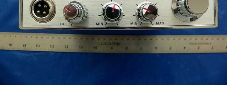
Click to zoom
Application Details
- Equipment Class
- TNB - Licensed Non-Broadcast Station Transmitter
- Date of Grant
- Mar 17, 2007
- Application Purpose
- Original Equipment
- Date of Application
- Mar 17, 2007
- Equipment Note
- 40 Channel CB Mobile Transceiver
- Frequency Range
- 26.96500000 - 27.40500000
- Company
- Midland Radio Corporation
- Country
- United States
Documents & Files
Document Text
Text extracted from the exhibit documents filed with the FCC. Open a document above to read the original.
Users Manual
www.midlandradio.com www.midlandradio.com 5001z 5001z | | 40 Channel Citizen Band Mobile Radio 40 Channel Citizen Band Mobile Radio Owner’s Manual Owner’s Manual Model 5001z Owner’s Manual Page 2 www.midlandradio.com Table of Contents Table of Contents Welcome to the World of Midland Electronics Major 5001z Features Installation Location Mechanical Mounting Power Wiring Mounting the Main Unit Installation of Microphone Hanger CB Antenna Antenna: How to Select, Position, Install and Tune the Right One for You Where you Locate your Antenna Does Make a Difference Antenna Installation Tuning your Antenna 5001z Front Panel Features and Operation How to Operate your Transceiver Back Panel Features and Operation How to Operate the Public Address Technical Specifications Limited Warranty Service and Technical Support Other Midland Products 2 3 3 4 4 4 5 5 5 6 6 6 6 6 7-8 8 9 9 10 11 12 13 Model 5001z Owner’s Manual Page 3 www.midlandradio.com Welcome to the World of Midland Electronics Welcome to the World of Midland Electronics Congratulations on your purchase of a state-of-the-art Midland 5001z mobile CB radio. In the years ahead, you can expect to realize time and again why Midland holds the front running position among CB users everywhere. You will come to know that American Original is not just a slogan, but the heading of long list of hearable, seeable benefits. As your Midland CB experience unfolds and grows we hope you will remember that CB radios are only one kind of electronic excellence available under the Midland name. Your 40 channel CB radio represents the state of the art in high tech engineering. The unit incorporates microprocessor controlled PLL circuitry for precise tuning. The 5001z is a classic style CB that is skillfully constructed with the finest components. This radio is designed for reliable and trouble-free performance for years to come. Enjoy! Major 5001z Features Major 5001z Features • 40 CB Channels • 4 Watt Output Power • X-TRA TALKMic Gain • 4- Pin Front Panel Mic Connector • PA Function • Switchable Noise Blanker(NB) • Instant Channel 9 • Dimmer Control • RF Gain • Automatic Noise Limiter(ANL) • Push to talk ergonomically designed microphone • 9 ft coil Mic cord • Includes mounting bracket/hardware and fused DC power cord Midland Radio Corporation Hereby certifies that this unit has been designed, manufactured, FCC type accepted and certified in accordance with part 95 and Part 15, Subpart C of the current FCC rules and regulations as of the date of manufacture. Model 5001z Owner’s Manual Page 4www.midlandradio.com Installation Installation This transceiver may be installed in any 12-volt negative ground-system car or truck. Most current U.S. and foreign vehicles use a negative system, but some older models and some newer large trucks may have a positive ground. Check the requirements for your vehicle before you begin installation. Generally, you have a negative-ground system if the minus (-) battery terminal is connected to the motor block. Contact your dealer in the event you are unable to determine your vehicle's polarity system. Location Your new Midland CB is designed to be installed under the dash or vertically on a console of your vehicle. Safety and convenience are the primary considerations in deciding exactly where to locate your radio. Caution: Be sure that the unit is located so that it does not interfere with the driver, sup- plemental restraint systems (air bags), or impair access to any controls. Connecting cables must be routed and secured in such a manner as not to interfere with the opera- tion of the brake, accelerator or other controls. Interference from either the unit or con- necting cables may contribute to the loss of control of the vehicle. Mechanical Mounting Step 1: Use the mounting bracket as a template for marking the location of screw holes under the dash. Use a nail or other sharp pointed object to mark the hole locations. Step 2: Drill a 1/8" hole for each screw hole in the mounting bracket. Attach the bracket to the dash with the Phillips head sheet metal screws provided. NOTE: Extreme care should be exercised when drilling into the dash to avoid damage to under-dash electronic ignition, cruise control, instrument and/ or accessory wiring. Step 3: Attach removable 3-pin plug-in DC cord to polarized DC jack on the rear of the transceiver. Step 4: Locate and secure the radio into the mounting bracket, allowing working space for later power connections. Model 5001z Owner’s Manual Page 5www.midlandradio.com Installation Continued... Installation Continued... Power Wiring (negative ground only) Step 1: If you have not determined whether your vehicle has a negative or positive ground, do so now. Then disconnect the negative lead from the battery to prevent short circuits that can occur during wiring. Do not connect this transceiver to positive ground electrical systems. Step 2: With negative ground: A. Connect the positive (RED WIRE) the one with in-line fuse holder to either the ( a ) fuse block ( b ) cigarette lighter or ( c ) directly to the positive post on your battery. Usually, the fuse block is the most convenient connecting point. It is also possible to connect to the Accessory terminal on the fuse block or ignition switch, so that your CB automatically goes off when the ignition goes off. B. Then tightly connect the ground (BLACK WIRE) directly to the vehicle's metal frame. A good direct metal-to-metal ground is essential for optimum performance. Mounting the Main Unit Step 1: Loosen the retaining knobs on each side of the mounting bracket to give enough space for the unit to slide between the two bracket arms. Step 2: Position the main unit between the bracket arms in line with the retaining knobs. Set the height and angle for optimum operating comfort and accessibility. Step 3: Tighten the retaining knobs. Installation of Microphone Hanger Mounting holes are provided on the microphone hanger bracket. The bracket can be attach…
Text truncated - open the document above for the full version.
External Photos
Midland Radio Corporation FCC ID: MMA5001Z Report #: R0702122-95 Page 30 of 33 FCC Part 95 Report EXHIBIT C - EUT PHOTOGRAPHS EUT – EUT with all Accessories EUT – Front View Midland Radio Corporation FCC ID: MMA5001Z Report #: R0702122-95 Page 31 of 33 FCC Part 95 Report EUT – Rear View EUT – Bottom View
ID Label/Location Info
Midland Radio Corporation FCC ID: MMA5001Z Report #: R0702122-95 Page 28 of 33 FCC Part 95 Report EXHIBIT A - FCC ID LABELING AND WARNING STATEMENT FCC § 2.925 Identification of equipment (a) Each equipment covered in an application for equipment authorization shall bear a nameplate or label listing the following: (1) FCC Identifier consisting of the two elements in the exact order specified in §2.926. The FCC Identifier shall be preceded by the term FCC ID in capital letters on a single line, and shall be of a type size large enough to be legible without the aid of magnification. Example: FCC ID XXX123. XXX—Grantee Code 123—Equipment Product Code Proposed Label Location on EUT Back View of EUT / Proposed FCC ID Location FCC ID: MMA5001Z
Internal Photos
Midland Radio Corporation FCC ID: MMA5001Z Report #: R0702122-95 Page 32 of 33 FCC Part 95 Report EUT – Cover off View EUT – Components View Midland Radio Corporation FCC ID: MMA5001Z Report #: R0702122-95 Page 33 of 33 FCC Part 95 Report EUT – Solder View END OF REPORT
Parts List/Tune Up Info
ADJUSTMENT PROCEDURES 1-1 PREPARATION REQUIRED TEST EQUIPMENT Equipment Grade and Range Equipment Grade and Range DC power supply Output voltage: 13.8V DC Current capacity: 4A or more Standard signal generator(SSG) Frequency range: 0.1-150MHz Output level: 0.1uV-100mV External speaker Input impedance: 8Ω Capacity: 10W or more DC voltmeter Input impedance: 50kΩ/V DC or better Frequency counter Frequency range : 0.1–100MHz Frequency accuracy : ±1 ppm or better Sensitivity : 100 mV or better RF power meter (terminated type) Measuring range : 1–10 W Frequency range : 2–50MHz Impedance : 50Ω SWR : Less than 1.2 : 1 Distortion meter Frequency range: 1KHz+/-10% Measuring range: 1-100% SINAD Meter Frequency range: 1KHZ+/-5Hz Optional Frequency Range: 300 Hz to 10 kHz ±5% Input Level Range: 100mV to 15V Display Range: 0 to 60 dB 1-2 PLL ADJUSTMENTS Measurement Adjustment point Adjustment Adjustment condition Unit Location Va l u e Unit Adjust Lock Voltage z Operation channel: CH 19 Main Connect a digital multi-meter or oscilloscope to Resistor R68 3.0V – 3.8V Main T4 Reference frequency z Operation channel: CH 19 z Connect an RF power meter or a 50 dummy load to the antenna connector. z Transmitting Main Loosely couple the frequency counter to the antenna connector. 27.185MHz Main Vc1 1-3TRANSMITTER ADJUSTMENTS Measurement Value Adjustment point Adjustment Adjustment condition Unit Location Unit Adjust Output power z Operation channel: CH 19 z Transmitting Main Connect an RF power meter to the antenna connector. 3.8-4.3W Main T5 T6 L16 1-4 RECEIVER ADJUSTMENTS Measurement Value Adjustment point Adjustment Adjustment condition Unit Location Unit Adjust Sensitivity z Operation channel: CH 19 z Connect a Standard signal generator’s output to the antenna connector and set as: Level: 1.0uV* z Receiving Main Connect a External speaker and a sinad meter to EXT. Maximum sensitivity Main T1 T2 T3 L102 L104
Test Report
Note: This test report is for the customer shown above and their specific product only. It may not be duplicated or used in part without prior written consent from Bay Area Compliance Laboratories Corp. This report must not be used by the customer to claim product certification, approval, or endorsement by NVLAP, NIST, or any agency of the Federal Government (REV.1) FCC PART 95 EMI MEASUREMENT AND TEST REPORT For Midland Radio Corporation 5900 Parretta Drive Kansas City, MO 64120 FCC ID: MMA5001Z Model: 5001z This Report Concerns: Original Report Product Type: 40 Channels CB mobile transceiver Test Engineer: Dan Coronia Report Number: R0702122-95 Report Date: 2007-03-08 Reviewed By: Daniel Deng, Test Engineer Prepared By: (18) Bay Area Compliance Laboratories Corp. (BACL) 1274 Anvilwood Ave. Sunnyvale, CA 94089 Tel: (408) 732-9162 Fax: (408) 732-9164 Midland Radio Corporation FCC ID: MMA5001Z Report #: R0702122-95 Page 2 of 33 FCC Part 95 Report TABLE OF CONTENTS GENERAL INFORMATION.......................................................................................................................................4 PRODUCT DESCRIPTION FOR EQUIPMENT UNDER TEST (EUT) .....................................................................................4 MECHANICAL DESCRIPTION.........................................................................................................................................4 EUT PHOTO.................................................................................................................................................................4 OBJECTIVE...................................................................................................................................................................5 RELATED SUBMITTAL(S)/GRANT(S).............................................................................................................................5 TEST METHODOLOGY..................................................................................................................................................5 MEASUREMENT UNCERTAINTY....................................................................................................................................5 TEST FACILITY.............................................................................................................................................................6 SYSTEM TEST CONFIGURATION ..........................................................................................................................7 JUSTIFICATION.............................................................................................................................................................7 BLOCK DIAGRAM.........................................................................................................................................................7 EQUIPMENT MODIFICATIONS.......................................................................................................................................7 LOCAL SUPPORT EQUIPMENT LIST AND DETAILS........................................................................................................7 INTERFACE PORTS AND CABLING.................................................................................................................................7 SUMMARY OF TEST RESULTS ...............................................................................................................................8 §2.1046, §95.639 – RF OUTPUT POWER ..................................................................................................................9 APPLICABLE STANDARD..............................................................................................................................................9 TEST PROCEDURE........................................................................................................................................................9 TEST EQUIPMENT LIST AND DETAILS...........................................................................................................................9 TEST SETUP DIAGRAM.................................................................................................................................................9 ENVIRONMENTAL CONDITIONS..................................................................................................................................10 TEST RESULTS...........................................................................................................................................................10 PLOTS OF CONDUCTED OUTPUT POWER: ...................................................................................................................11 LOW CHANNEL..........................................................................................................................................................11 MIDDLE CHANNEL.....................................................................................................................................................11 HIGH CHANNEL..........................................................................................................................................................12 §2.1047 & §95.637 - MODULATION CHARACTERISTICS.................................................................................13 APPLICABLE STANDARD............................................................................................................................................13 TEST PROCEDURE......................................................................................................................................................13 TEST EQUIPMENT LIST AND DETAILS.........................................................................................................................13 ENVIRONMENTAL CONDITIONS...........................................…
Text truncated - open the document above for the full version.
Test Setup Photos
Midland Radio Corporation FCC ID: MMA5001Z Report #: R0702122-95 Page 29 of 33 FCC Part 95 Report EXHIBIT B - TEST SETUP PHOTOGRAPHS Radiated Emissions – Front View Radiated Emissions – Rear View
Contact Information
Applicant
Butch Rittmann(Director of Operations)
Test Firm
Bay Area Compliance LaboratoryJohn Chan
Technical Specifications
| # | Rule Parts | Frequency Range | Power Output | Emission | Tolerance |
|---|---|---|---|---|---|
| 1 | 95D | 26.965 MHz - 27.405 MHz | 4 W | 8K00A3E | 0.0050000000 % |
Other Applications from Midland Radio Corporation

MMAMXMC95
Jun 10, 2026Wireless Bluetooth Microphone
Equipment Class
JAB - Part 15 Class B Digital Device
MMAMXT295
Jun 08, 2026GMRS Radio
Equipment Class
TNF - Licensed Non-Broadcast Transmitter Held to Face
MMACLIPTALK
Apr 27, 2026Transceiver
Equipment Class
DTS - Digital Transmission System
MMABR200S
Jan 13, 2026BUSINESS BAND TWO-WAY RADIO
Equipment Class
TNF - Licensed Non-Broadcast Transmitter Held to Face
MMAGXT67
Oct 29, 2023GMRS RADIO
Equipment Class
TNF - Licensed Non-Broadcast Transmitter Held to Face