MMA701545BUHF TRANSCEIVER
Midland Radio Corporation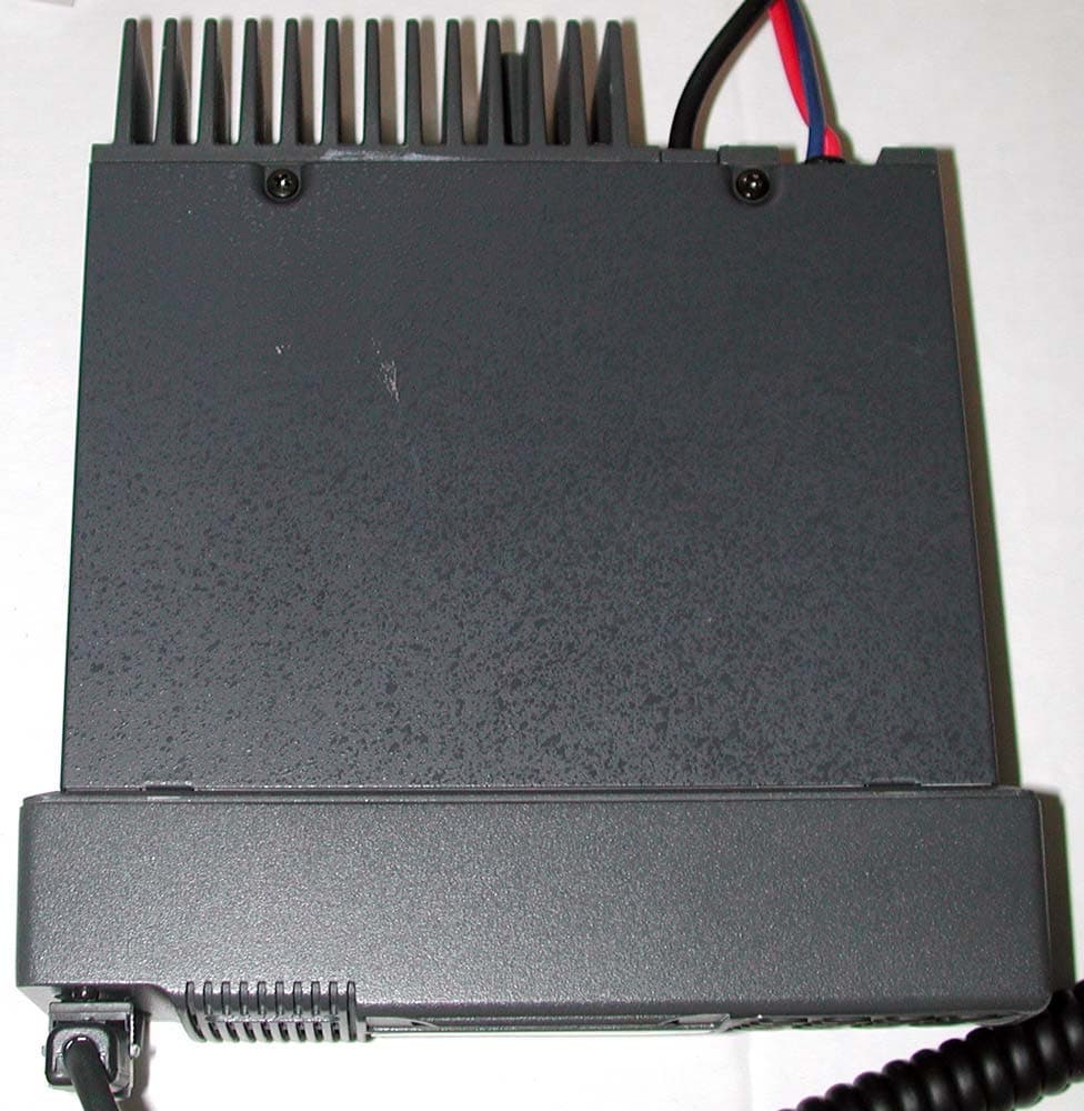
Click to zoom
Application Details
- Equipment Class
- TNB - Licensed Non-Broadcast Station Transmitter
- Date of Grant
- Jul 27, 2006
- Application Purpose
- Original Equipment
- Date of Application
- Jul 27, 2006
- Equipment Note
- UHF TRANSCEIVER
- Frequency Range
- 440.00000000 - 475.00000000
- Company
- Midland Radio Corporation
- Country
- United States
Documents & Files

Document Text
Text extracted from the exhibit documents filed with the FCC. Open a document above to read the original.
Users Manual
Model 70-1545 Mobile Transceiver SERVICE MANUAL 6KEN SOFTWARE VERSION Manual # KW208SM-6KEN 2 SCOPE OF THIS MANUAL This manual covers the KG208 Series for the following bands: KG208-08A.... 66-88 MHz. KG208-15A.... 134-162 MHz. KG208-15B.... 146-174 MHz. KG208-20A.... 176-208 MHz KG208-20B.... 208-245 MHz. KG208-20C.... 240-276 MHz. KG208-40SA.... 300-335 MHz KG208-40A.... 335-365 MHz KG208-40B.... 365-400 MHz KG208-40C.... 400-435 MHz. KG208-40DS.... 420-455 MHz KG208-40D.... 440-475 MHz KG208-40E.... 465-500 MHz KG208-40F.... 485-520 MHz The KG208-03, 30 –50 MHz band will be covered in an addendum to this manual. 3 INDEX SUBJECT PAGE SCOPE OF MANUAL 2 INDEX (THIS PAGE) 3 DRAWING INDEX 4 SPECIFICATIONS 5 SECTION 1: INTRODUCTION 6 Applications 6 Radio Features 6 Safety Information 6 Model Number Coding 7 Initial inspection 8 Standard Package Contents / Drawing 8 SECTION 2: INSTALLATION 9 SECTION 3: OPERATION 11 Control Functions, Control panel Drawing 11 Display ICONS 12 Operating the Radio 13 Advanced Features 15 Special Keypad Functions 17 SECTION 4: CIRCUIT DESCRIPTION 20 Operating Voltage Control 20 Receiver 20 Transmitter 22 PLL 23 Logic Unit 23 Control Unit 23 SECTION 5: SERVICING INFORMATION 25 Test Equipment and Tools 25 Tuning and Adjustments 25 Disassembly Procedures 27 DRAWINGS 33 REPLACEMENT PARTS LISTS 50 4 DRAWING INDEX DRAWING PAGE EXPLODED VIEW 33 MAIN UNIT SCHEMATIC 66-88 MHZ 35 MAIN UNIT SCHEMATIC 134-174 MHZ 36 MAIN UNIT PCB LAYOUT 37 MAIN UNIT SCHEMATIC 176-276 MHZ 38 MAIN UNIT SCHEMATIC 300-520 MHZ 39 CONTROL UNIT SCHEMATIC 40 CONTROL UNIT PCB LAYOUT 41 LOGIC UNIT PCB LAYOUT 42 LOGIC UNIT SCHEMATIC 43 VCO UNIT SCHEMATIC 66-88 MHZ 44 VCO UNIT SCHEMATIC 134-174 MHZ 45 VCO UNIT SCHEMATIC 176-276 MHZ 46 VCO UNIT SCHEMATIC 300-520 MHZ 47 VCO UNIT PCB LAYOUT 48 DCS UNIT SCHEMATIC & PCB 49 5 SPECIFICATIONS KG208 Mobile Transceiver GENERAL Frequency Range 30 MHz Band (1) 80 MHz Band VHF Band 200 MHz Band UHF Band Designated 03 Designated 08 Designated 15 Designated 20 Designated 40 A: 30 - 40 MHz A: 66 - 88 MHz A: 134-162 MHz A: 176-208MHz SA: 300-335 MHz B: 40 - 50 MHz B: 146-174 MHz B: 208-245 MHz A: 335-370 MHz C: 45 - 55 MHz* C: 240-276 MHz B: 365-400 MHz C: 400-435 MHz * Special Order DS: 420-455 MHz D: 440-475 MHz (1) This band will be covered in an addendum) E: 465-500 MHz F: 485-520 MHz Number of Channels 200 channels or 100 channels with channel name Channel Spacing 12.5, 20, 25, 30 kHz programmable by channel Mode of Operation Simplex or Semi duplex, Push To Talk Antenna Impedance 50 Ohms unbalanced Power Supply 13.6 V DC +/- 20% negative ground Power Consumption TX: <3 A @ 10 W, <5 A @ 25 W, <8A @ 40 W, RX: 330 mA standby, 370mA receive-mid volume, 525 mA receive-max volume Environmental Conditions Ambient temperature: -30 C to +60 C (-22 F to +140 F) Relative humidity: 95% at 35 C Construction Die cast aluminum chassis and control unit, stamped steel covers Dimensions High power model Standard model 166 mm (6.54” width 166 mm (6.54” width 50 mm (1.97”) high 50 mm (1.97”) high 195 mm ((7.7”) long 173 mm (6.81”) long Weight 1.7 kg (3.74 lb.) 1.5 kg (3.3 lb.) Color Dark gray, textured Dark gray, textured TRANSMITTER RF Power Output 30 MHz Band 80 MHz Band VHF Band 200 MHz Band UHF Band Models are available at 40 W 25 W 5-10 W (10 W) 25 W 5-10 W (10W) 10 W, 25 W & 40 W 10-25 W (25W) 10-25 W (25W) in VHF and UHF bands 20-40 W (40W) 20-40 W (40W) All powers are programmable high or low (two levels) by channel and selectable at front panel Low power levels are adjustable down to 2 W. Max. Frequency Deviation Wide band: +/- 5 kHz, Narrow band, +/- 2.5 kHz Frequency Stability + 0.0003% Frequency Response Within +1, -3dB of 6 dB/octave pre-emphasis from 300 to 3000 Hz, 1 kHz ref. Signal To Noise Ratio Wide band: more than 50dB at 1 kHz 70% modulation Narrow band: more than 45 dB at 1 kHz 70% modulation Modulation Distortion Less than 3% at 1kHz 70% modulation Spurious and Harmonics More than 70 dB below rated power RECEIVER Intermediate Frequency 1 st IF: 48.5 MHz, 2 nd IF: 455 kHz Frequency Stability + 0.0003% Sensitivity Less than 0.4 μV for 20 dB quieting, Less than 0.25μV for 12 dB SINAD Squelch Sensitivity Less than 0.25 μV Selectivity More than 70 dB at 25 kHz point Blocking More than 90 dB Intermodulation More than 70 dB Spurious Response More than 70 dB AF Response Within +1, -3 dB of 6 dB/octave de-emphasis from .3 to 3 kHz, 1 kHz Ref. AF Output Internal speaker: 4 W max, 2.5 W @ < 5% distortion into 4 Ohms, 1 kHz, 70% modulation External Speaker: 6 W max, 4 W @ <5% distortion into 4 Ohms, 1 kHz, 70% modulation Signal to Noise Ratio Wide band, 25 KHz: more than 50 dB at 1 kHz 70% modulation Narrow band, 12.5 KHz: more than 45 dB at 1kHz 70% modulation Due to constant technological developments and changes, specifications may vary without notice. Options and specifications may vary slightly in different countries to suit local requirements. 6 SECTION 1. INTRODUCTION 1.1 INTRODUCTION 1.1.1 APPLICATIONS The KG208 Series mobile radio transceivers provide professional communications for a wide variety of applications. Government agencies, police departments, security and public safety agencies, courier and freight companies, construction, airport ground services, petroleum and utility industries may use the radio for reliable communications. KG208 radios use sophisticated technology and microprocessor control to allow the installer to quickly change the radio’s characteristics. Any computer-equipped dealer or service shop with the necessary software and programming manual can easily program your radio to your specific operating requirements. The radio’s many advanced features will add to the usefulness, safety and efficiency of any communications system. 1.1.2 RADIO FEATURES • Simplex or semi-duplex operation • High performance specifications • Wide non-tuning bandwidth • Wide range of standard bands for use in many countries • Wide-band/Narrow band by channel • IBM-PC…
Text truncated - open the document above for the full version.
External Photos
MIDLAND RADIO CORP. FCC ID: MMA701545B EXTERNAL PHOTOS
Internal Photos
MIDLAND RADIO CORP. FCC ID: MMA701545B INTERNAL PHOTOS OPEN UNIT WITH LOGIC AND VXO OPEN UNIT WITHOUT LOGIC AND VCO MAIN BOARD – TOP MAIN BOARD TOP WITH SHIELD MAIN BOARD BOTTOM VCO BOARD – TOP VCO BOARD – BOTTOM CONTROL BOARD – TOP FRONT BOARD – BOTTOM LOGIC BOARD – TOP LOGIC BOARD BOTTOM – WITH SHIELD LOGIC BOARD – BOTTOM – NO SHIELD
Operational Description
20 SECTION 4 CIRCUIT DESCRIPTION 4.1 OPERATING VOLTAGE CONTROL There is a programmable, Power-Off Feature which turns off the radio after a preset time of non-activity to prevent discharging of the vehicle battery. This feature is mentioned in the discussion of each circuit under its control. Battery voltage enters the radio on the RED/BLUE battery cable. Fuses are located in this cable. D22 protects the radio from reverse voltage by causing the fuses to blow. LF1 filters noises existing on the automobile supply. The power switch on the control unit lowers the bias on Q16 which turns on Q23 and Q15 supplying power to the radio. The switched battery voltage is regulated to 5 Volts by IC1O and supplied to all circuits which are not under control of the power-off timer. Regulator IC13 removes impulse noise from the 12 V line and is used to switch off the power to many circuits upon input from the TIMER IN signal from the logic board at CN6-2. Q24 filters the 12 V supply to the audio power amplifier. Q13 and Q14 control operating voltage to an external relay at CN1O-5, DECODE HORN for signaling that a call has been received. Q14 is turned on by an active high DECODE HORN input from the logic board on CN6-19. Q14-C pulls Q13-B low turning it on and supplying a voltage to the relay. IC12 supplies a regulated 7 Volts to the circuits under control of the power-off timer. During transmit, the top half of Q12 turns off B+ to the receiver upon receiving an active high transmit command on the TX1 IN input at CN6-11. The lower half of Q12 provides an inverted active low PTT signal to the VCO at CN2-3. IC14 provides protection from wide variations in the power supply voltage. If the voltage drops below 8 V or rises above 18 V, a STOP OUT signal is output to the logic board on CN6-3 to stop the CPU and shut down the radio. 4.2 RECEIVER 4.2.1 RF SECTION The received signal enters the antenna connector and passes through Low-Pass Filter made up of L20, 21, 22, 23 and C134 through C 140. The Antenna Switch, D27 and D29, directs the signal to the receiver input at L1. L1 and L2, along with Varactors Dl and D2 tune the RF section to the selected frequency using a tuning voltage from IC4 derived from the PLL circuit. Q1 amplifies the RF and feeds the signal through a bandpass filter to TP1 and on to the mixer made up of T1, T2, D5& D6. The bandpass filter eliminates signals outside the desired band. A signal from the VCO local oscillator is also input to the mixer at CN1-4 to produce the 1st IF signal, 48.5 MHz. (refer to VCO UNIT). 4.2.2 VCO UNIT, RX Q301 is the receive oscillator. It is tuned by varactors D301 and D311 using the control voltage from the PLL circuit at CN4-6. L301 is adjusted to center the oscillator range in the desired band of frequencies. The oscillator output is amplified by IC301 and Q306 and sent to the receiver mixer on CN5-4 RX LOCAL. Operating voltage for the oscillators is filtered by Q308. Q304 switches voltage to the oscillator and gates Q306 amplifier on and off depending on the state of the Q305-C and the PTT line. Q303 supplies regulated voltage to IC301in both the receive and transmit modes. 21 4.2.3 HIGH IF (48.5 MHz) The IF passes through Crystal Filter XF1, IF Amplifier Q3, IF Transformer T3, Crystal Filter XF2, Amplifier Q4 and on to the input of IC1 -20. IC1 uses crystal X1 to generate 45.045 MHz to convert the 1st IF of 48.5 MHz to the 2nd IF of 455 kHz. 4.2.4 LOW IF (455 kHz) The 455 kHz IF is filtered by Ceramic Filters CF1 & CF2. IC1 also limits, detects the audio and provides a squelch (BUSY) signal, an RSSI signal (Receive Signal Strength Indication) for use in other circuits of the radio. Discriminator audio leaves IC1-11 to the Audio Processor IC8-40 (see Audio Processing). 4.2.5 SQUELCH The high frequency noise from the audio is passed through FVR1 and C34 to IC1-13. FVR1 provides an internal adjustment of the squelch range. The high frequency noise present in the audio is reduced when a signal is received. IC1 amplifies and detects the noise and compares it to the squelch threshold set by the operator to produce a squelch logic (BUSY) signal at pin 17. This is buffered by IC2 and used to control the Squelch Gate IC9 which breaks the audio path when no signal is present. Squelch control data originates in microprocessor, IC203 on the logic unit. Under control of impulses from the channel/squelch switch on the control unit, squelch data is generated by IC203 and appears on pins 41, 42, 43. These are combined to provide eight steps of squelch threshold vo1tage (SQ-0 thru SQ-7) which enters the main unit on CN6-13, is buffered by IC4 and goes on to the squelch circuit R26, R24, D7 to IC1-15. This voltage is compared to the detected noise level to generate the squelch logic (BUSY) signal mentioned in the last paragraph. In the transmit mode, the voltage is removed from the receiver which causes a loss of voltage on the anode of D7. This immediately mutes the receiver. 4.2.6 RECEIVER MUTE Operating voltage for the receiver circuits described above comes from IC12, 5 Volt Regulator. Q12 switches the voltage off during PTT to mute the receiver. Also, all voltage is removed upon activation of the power-off timer. 4.2.7 AUDIO PROCESSING Discriminator audio from IC1-11 goes to the Audio Processor IC8-40. IC8, contains the audio bandpass filter,300 to 3000 Hz, de-emphasis @ 6 dB/octave, voice inversion scrambler and CTCSS. The audio leaves on pin 12 and passes to Volume Control chip IC9-6. The volume control on the control unit changes the gain of IC9 by changing the bias on pins 3 and 5. Audio leaves IC9-7 and goes through the Squelch Gate Q10 which is controlled by the BUSY signal from the squelch circuit, the CTCSS decode from the audio processor and the DECODE signal from the logic unit. From the Squelch Gate, the audio goes to the Audio PA IC11-1. Operating voltage for the Audio PA is filtered by Q24 to minimize noise from the automobile 12 volt system. Speaker audio…
Text truncated - open the document above for the full version.
Parts List/Tune Up Info
51 MAIN AND VCO UNITS KG208-08A 66-88 MHZ BAND COMPLETE UNIT (SPECIFY BAND) 208MP87X C1 24 PF GRM40CH240J50PT C2, 470 PF GRM40B471K50PT C3,C15,C23 12 PF GRM40CH120J50PT C4 .5 PF GRM40CK0R5J50PT C5,C18 1000 PF GRM40B102K50PT C6 .1 UF GRM40B104K25PT C7,C11 33 PF GRM40CH330J50PT C8,C33,C46,C47,C60, C61,C129 470 GRM40B471K50PT C9,C12,C13,C22,C24,C27,C28 1000 PF GRM40B102K50PT C14 100 PF GRM40CH100D50PT C16 5 PF GRM40CH050C50PT C17,C29 5 PF GRM40CH050C50PT C20,C42,C72 100 PF GRM40CH101J50PT C21,C25,C36 22 PF GRM40CH220J50PT C26 15 PF GRM39CH150J50PT C30 .68 UF ECST1CY684R C31 .027 UF GRM40B273K50PT C32 390 PF GRM40CH391J50PT C34,C54,C68 .01 UF GRM40B103K50PT C35,C56,C67,C81,C82,C84,C85,C89, C91, 1 UF ECST1CY105R C36 22 PF GRM40CH220J50PT C37 2200 PF GRM40B222K50PT C38,C69,C78,C79,C86 47 PF GRM40CH470J50PT C39,C40, C41,C43,C50,C64,C75, C90 C94,C97 .047 UF GRM40B473K25PT C44 1 UF ECST1CP105R C45,C59, C93 .001 UF GRM40B102K50PT C48,C53,C55,C76 .015 UF GRM40B153K50PT C49,C51, 47 PF UWT1C470MCR1GB C54 .022 UF GRM40B472K50PT C57,C62,C95 .1 UF GRM42-6B104K50PT C58 .22 UF ECST1VY224R C63 .5 PF GRM40CK0R5B50PT C65,C71,C80,C96 1 PF UWP1H010MCR1GB C66,C87 2.2UF ECST1CY225R C70 220 PF GRM40CH221J50PT C74 6800 PF GRM40B682K50PT C77 8200 PF GRM40B823K25PT C83 .47 UF ECST1DP474R C87 2.2 UF ECST1CY225R C88 3300 PF GRM40B332K50PT C95 .1 UF GRM42-6B104K50PT C98,C99 4.7 PF UWT1E4R7MCR1GB C100 .047 UF GRM40B473K25PT C101,C103,C107,C108 1 UF ECST1CP105R C102 .47 UF ECST1DP474R C104,C114,C115,C117,C119,C124, C126,C132,C141,C142,C143,C149, C150,C151,C152,C157,C160 .001 UF GRM40B102K50PT C105,C160 1000 UF KMG16VB-1000M C106,C111 470 UF KMG35VB-470M C108 1 UF ECST1CY105R C112, C120 33 PF GRM40CH680J50PT C116 C118 7 PF GRM40CH680J50PT GRM40CH680J50PT C121 C123 33 PF GRM40CH330J50PT UWT1E330MCR1GB C125,C163,C165 4.7 PF UWT1E4R7MCR1GB C127 1 PF GRM40CK010B50PT C128,C130 33 PF GRM40CH330J50PT C131 56 PF GRM40CH560J50PT C133 47 PF UC342H4700J C134 7 PF UC232H0560J C135,C136 10 PF UC232H0680J C137 5 PF UC232H0330J C138,C139 1 PF UP050SL3R9M/NAC C140 2 PF UP050SL020M/NAC C144 4.7 PF UWT1E4R7MCR1GB C145 2.2 UF ECST1CY225R C153,C154 100 UF KMG16VB-100M C158, 470 PF GRM40B471K50PT C159 .047 UF GRM40B473K25PT C161 1 UF C162 .01 UF EST1CY105R GRM40B103K50PT C163 UWT1E4R7MCR1GB C167 C4AT C5AT CD1 DISCRIMINATOR GRM40B471K5-PT GRM40CH180J50PT GRM40CH270J50PT CDBM455C7 CF1 LO IF CERAMIC FILTER, 455 KHz CFUM455G CF2 LO IF CERAMIC FILTER, 455 KHz CFWM455E CN1S CONN. 5124-04BHPB CN2S CONN. VCO 5124-06BHPB CN3S CONN. KEYPAD 4A-S498 CN4S CONN. CONTROL UNIT 4A-S497 CN5S CONN. LOGIC UNIT LPC-22FD CN6S CONN. LOGIC UNIT LPC-22FD CN7P CONN. ACCY. JACK 53014-0810 CN8P CONN. ACCY. JACK 53014-0310 CN10S CONN. ACCY. 4A-S412 CN10P CONN. ACCY./ SPKR JUMPER 4A-S413 CN15P CONN. DCS 236A-08-90-134 D1 1SV232-TPH3 D2 1SV231-TPH3 D3 1SV231-TPH3 D4 1SV232-TPH3 D5,D6 1SS271-TE85R 52 D7, D8,D11,D14,D16,D17,D19,D30,D34 1SS355 D9,D10 DAN217K-T146 D12,D13 1SS356-TW11 D18 1SS181-TE85R D21 UDZ2.2B-TE17 D22 DF10SC4M(4100) D23 1SR154-400TE25 D24 DAN235K-T146 D26,D28 1SS357-TPH3 D27,D32 UM9401F D29 UM9415 D33 MA8056-HM(TX) FVC1 10 PF POWER BALANCE TZ03T200FR169 FVC2 20 PF CLOCK ADJUST CTZ2E-20C-W2P FVR1 20K INTERNAL SQUELCH EVM-7JSX30B24 FVR2 20K MODULATION EVM-7JSX30B24 FVR5 TONE MODULATION EVM-7JSX30B15 FVR7 10K LOW PWR ADJUST CHIP VR G3AT 10K FVR8 2K HIGH PWR ADJUST EVM-7JSX30B23 FVR9 VSWR PROTECT ADJUST EVM-7JSX30B23 IC1 LOW IF / SQUELCH / DETECTOR TK10487M-TR IC2 BUSY LOGIC BU4S81-TR IC3 PLL MBM1505PF-G-BND-TF IC4 DCT / SQUELCH TS272CD IC5 UNLOCK SWITCH BU4S66-TR IC8 AUDIO PROCESSOR AK2342B IC9 VOLUME CONTROL CHIP M5222FP-600C IC10 5 V REG AN78L05M IC11 AUDIO PA LA4425A IC12 5V REG TA78M05F-TE16L IC13 POWER CONTROL PQ12RH11 IC14 STOP CONTROL NJM2405M-T1 IC15 PA POWER CONTROL TA75S01F-TE85R L1, L6 RF TUNE #3087 L2, L5 RF TUNE #3088 L3 1 UH ELJ-NA4R7JF L7 .1 UH LQN1AR10J04 L8 .47 UH ELJ-NCR47KF L9 1.5 UH ELJ-NA1R5MF L11 .47 UH ELJ-NAR47MF L12 .68 UH NL322522TR68J L13, L14,L25 BLM21B421SPT L15 #1092(R12-H510Y) L16 4A-S418 L17,L18,L26 FBA04VB450KD-00 L19 LPF 4A-S547 L20 LPF 4A-S546 L21 LPF 4A-S544 L22 LPF 4A-S545 L23 LPF 4A-S544 L24 4A-S419 L27 4A-S369B LF1 POWER FILTER BNX 002-01 OSC1 12.0 MHZ VCXO VT50P-14 PM1 PA MODULE M67742-01 PS1 THERMAL PA CONTROL PTH9C32BB471Q-T Q1 RF AMP 3SK177-T1-U72 Q2 PTT/RX MUTE DTA144EUA-T106 Q3 HI IF AMP 2SK508-T1B-K53 Q4 HI IF AMP 2SC4250-TE85R Q5 PLL CONTROL 2SK1133 Q6 PLL CONTROL 2SJ-166-T1B Q7 PLL CONTROL UMC2-TR Q8 MIC MUTE IMX1-T110 Q9 TONE N / W MOD CONTROL DTC314TK-T146 Q10 SQUELCH GATE 2SK209-Y-TE85R Q11 UNLOCK CONTROL FMG9A-T148 Q12 TX CONTROL 1MX1-T110 Q13 DECODE HORN SWITCH RN6001-TE12R,C Q14 DECODE HORN CONTROL DTC314TK-T146 Q15 PA DC SWITCH 2SA1771 Q16 DC POWER CONTROL 2SA1434-TB Q17 PRE DRIVER AMP 2SC3356-T1B Q18 DRIVER AMP 2SC1947-01 Q19 DRIVER / POWER CONTROL 2SB906-Y-TE16L Q20 POWER CONTROL IMX1-T110 Q21 POWER CONTROL DTB143EK-T146 Q22 POWER CONTROL RN1507-TE85R Q23 POWER SWITCH DTC124EUA-T107 Q24 AUDIO B+ FILTER 2SC4684-TE16R Q25 SWITCH UMC2-TR Q26 N / W MOD CONTROL 2SA1434-TB Q27 N / W BPF FILTER SWITCH DTC314TK-T146 Q28 N / W BPF FILTER SWITCH 2SK209-Y-TE85R Q29 N / W DISC CONTROL 2SK209-Y-TE85R Q30 BEEP AMP RN1403-TE85R R1,R2 100K MCR10EZHJ104 R3 10K MCR10EZHJ103 R4 1.8K MCR10EZHJ152 R5 270 MCR10EZHJ181 R6 15K MCR10EZHJ153 R7, R8 470 MCR10EZHJ470 R9 , R11 100K MCR10EZHJ104 R10 10 MCR10EZHJ100 R12 56 MCR10EZHJ560 R13 6.8K MCR10EZHJ682 R14 270 MCR10EZHJ271 R15 22K MCR10EZHJ223 R16 100 MCR10EZHJ101 R17 15K MCR10EZHJ153 R18 82K MCR10EZHJ823 R19 18K MCR10EZHJ183 R20 1K MCR10EZHJ102 R21 1.2K MCR10EZHJ122 R22 82K MCR10EZHJ823 R23,R24, 10K MCR10EZHJ103 R25 2.7K MCR10EZHJ272 R26 1K MCR10EZHJ102 53 R27 390K MCR10EZHJ394 R28 820 MCR10EZHJ821 R29 10K MCR10EZHJ103 R30 1K MCR10EZHJ102 R31 2.7K MCR10EZHJ272 R32 3.9K MCR10EZHJ392 R33 10K MCR10EZHJ103 R34 47K MCR10EZHJ473 R35 1K MCR10EZHJ102 R36 10K MCR10EZHJ103 R37 47 MCR10EZHJ470 R38 39K MCR10EZHJ393 R39 100 MCR10EZHJ101 R40 680 MCR10EZHJ471 R41 2.7K MCR10EZHJ272 R42 1M MCR10…
Text truncated - open the document above for the full version.
Parts List/Tune Up Info
25 SECTION 5. SERVICING INFORMATION CAUTION: This radio uses surface mount construction. It is recommended that servicing may be limited to replacement of complete modules and non-surface mount components. Component level servicing should not be attempted unless the engineer or technician is very familiar with surface mount repair techniques and has all of the necessary specialized tools and equipment. 5.1 TEST EQUIPMENT AND TOOLS ITEM DESCRIPTION 1. DMM (Digital Multi-meter) 2. Audio Generator 10 Hz To 10,000 Hz 3. Regulated DC Power Supply with Volt and Amp meters, adjustable up to 15 V @ 15 Minimum 4. AC Voltmeter Analog Type preferred 5. Test Set With Signal Generator, Frequency Counter, Watt-Meter/Load, Deviation Meter, CTCSS/DCS. If test set is not available, separate equipment may be used for these functions, 6. Complete Set Of Small Hand Tools. 7. Temperature Controlled Soldering Iron. 8. Desoldering Braid Or Vacuum Type Desoldering Iron. 5.2 TUNING AND ADJUSTMENTS 5.2.1 GENERAL All adjustments have been properly set at the factory and should not require readjustment in the field. If a module has been replaced, refer to the section which covers the adjustment or tuning of that module. Tuning tools should fit exactly. Use insulated, nonmetallic tools for all RF adjustments. Always use an antenna or 50 Ohm dummy load for transmitter tests. Do not key transmitter when connected to signal generator. Connect the radio to a regulated DC power. Adjust for 13.8 volts at the power supply terminals. Adjustments are to be made with the top and bottom covers removed. Refer to section 5.3 DISASSEMBLY PROCEDURES. 5.2.2 VCO ADJUSTMENTS Note: Adjustment should not be required unless parts or the entire module have been replaced. If replacement and readjustment of the VCO, after repair is made, program wide band low and high power test channels near the low end, center and high end of the band (six channels in all) with CTCSS of 100 Hz on all channels. Example, for VHF Band, 146-174 MHz, program channels at 146.1 high and low power, 160.1 high and low power, and 173.9 high and low power.. Remove these channels after testing 26 is completed and program customer frequencies. Use the low power channels for all VCO tests to minimize overheating of the radio. The VCO must be adjusted so that the phase detector voltage remains between 1V and 5 V over the entire range of frequencies used. 1. To access the VCO, remove the top cover, 2 black screws, and the VCO shield, 5 brass screws. 2. Select the center channel which was programmed for tuning adjustments. Connect DMM to TP2 located on the left edge of the main board. 3. Adjust L301 located on the lower left, for 3 V in the RX mode. 4. Adjust L305 located on the lower right, for 3 V in the TX mode. 5. Check both RX ant TX VCO at highest and lowest frequency to make certain that voltage remains between 1 V and 5 V. Make minor readjustments as required. 6. For frequency spread of less than 10 mHz, re-install VCO shield and top cover. For spread over 10 MHz, leave covers off for later adjustment of FVR3O1 Modulation Balance control. 5.2.2 RECEIVER TUNING ADJUSTMENTS Note: If no repairs have been made to the radio, the sensitivity may be easily checked by testing the squelch sensitivity. Set the squelch to threshold and apply an on-frequency signal of .25 uV. If the Squelch opens, the sensitivity is OK. Typical squelch sensitivity is usually <.2uV, 1. Connect one lead of the Analog AC voltmeter to the high side of the speaker at the rear connector, pin 3 or 4 (jumper wire). Connect the other lead to the radio chassis. Remove bottom cover, 2 black screws. 2. Connect signal generator to antenna connector, select center channel frequency. 3. Check that RX VCO voltage at TP2 is near 3 V (+/- .5 V). Recheck VCO adjustment if necessary. 4. Select the center channel and adjust L1, L2 and L5, L6 or BPF1 (depends on band) and T3 for best sensitivity. Check sensitivity at the highest and lowest frequency and make minor adjustments if needed. Note that there may be a slight difference is sensitivity on these channels but it should not be outside of the sensitivity specifications. 5. After tuning is completed, sensitivity should be less than 0.4 uV for 20 dB quieting and less than .3 uV for 12 dB SINAD. Squelch sensitivity should be less than .25 uV at threshold. 5.2.3 FREQUENCY ADJUSTMENT 1. Connect frequency counter to the transmitter using proper attenuation. 2. Key the transmitter on a low power channel and adjust the trimmer on the reference oscillator OSC1 for correct frequency within 1 PPM. OSC1 is located on the front left side of the radio. This adjustment controls both the TX and RX frequencies. 5.2.4 TRANSMITTER POWER AMPLIFIER ADJUSTMENT Note: The mobile transmitter is designed for 20% duty cycle. Key the transmitter only long enough to make the adjustments. The transmitter contains internal protection against overheating which may reduce the power output if it is keyed for a long time. This may cause improper setting of the power output and possible damage to the radio.. 27 1. Connect wattmeter and load to antenna connector. 2. Select high power center channel and adjust the PWR HIGH (FVR8) for 25 Watts (40 Watts on high power models) or other desired power below maximum rated power. 3. Adjust FVC1 (FVC3) for maximum power and repeat step 2. 4. Check power at highest and lowest frequency and readjust FVC1 to balance the power. Power may be slightly lower at band extremes but should not exceed -1 dB. 5. Select low power center channel and adjust PWR LOW (FVR7) for ½ power or other low power setting. 6. The Reverse Protect feature protects the power amplifier from damage due to reflected power if the antenna becomes open or shorted. Select any high power channel. Key transmitter and adjust REVERSE PROTECT (FVR9) until power supply current just begins to drop. Slowly adjust in the other direction until current returns to normal. Repeat if necessary to make sur…
Text truncated - open the document above for the full version.
RF Exposure Info
7/28/2006 Page 1 of 3 FCCID: FCC RF Exposure Requirements General information : FCCID: Device category: Mobile per Part 2.1091 Environment: Controlled Exposure Mobile devices that operate under Part 90 of this chapter are subject to routine environmental evaluation for RF exposure prior to equipment authorization or use if they operate at frequencies of 1.5 GHz or below and their effective radiated power (ERP) is 1.5 watts or more. However, compliance with the power density limits of 1.1310 is not required. Antenna: The manufacturer does not specify any antenna to be used with this device. This device has provisions for operation in a vehicle, or a fixed location. Configuration Antenna p/n Type Max. Gain (dBi) Passenger car Any omni 3 Operating configuration and exposure conditions: The conducted output power is 40 watt. Typical use qualifies for a maximum duty cycle factor of 50%. The manufacturer also markets this device only for occupation use. - Part 2.1091 states that devices are excluded from routine evaluation if the EIRP is less than 2.46Watt (or 1.5WERP). - Vehicle Operation: The maximum antenna gain that can be used is 3dBi. A coaxial cable of the type RG 58 has a loss of 1dB for a length of 15 feet. MPE Calculation: The minimum separation distance is calculated as follows: The limit for occupation/controlled exposure environment above 300 MHz and below 1500 MHz is f/300 mW/cm 2 . 7/28/2006 Page 2 of 3 FCCID: Channel Frequency: 440-475 MHz The conducted power output is 45 watt. The coax loss was taken as 1 dB. Antenna gain was taken as 3 dBi 50% talk time in 6 minutes antenna gain f450:= Frequency in MHz GdBd2.15+:= gain in dBi gain numeric S f 300 := controlled exposure Gn10 G 10 := 300 for controlled S1.5= 1500 for uncontrolled Gn2.065= R Po Gn⋅() 4π⋅S⋅ () := Rinches R 2.54 := R44.138= distance in centimeters required for compliance Rinches17.377= W45:= power in Watts D1:= Duty Factor in decimal % (1=100%) E3.0:= exposure time in minutes U6:= (use 6 for controlled and 30 for uncontrolled ) PC E U := WexpW D⋅ E U ⋅:= PC0.5= percent on time Wexp22.5=Watts 0.5 = 50% CL1:= Coax loss Po17780:=mWattsdBd1:= 7/28/2006 Page 3 of 3 FCCID: Conclusion: The device complies with the MPE requirements by providing a safe separation distance of 125.6 cm between the antenna, including any radiating structure, and any persons when normally operated . Proposed RF exposure safety information to include in User’s Manual : “FCC RF Exposure Requirements: CAUTION: The antenna(s) used for this transmitter must not be co-located or operating in conjunction with any other antenna or transmitter. This device is approved with emissions having a source-based time-averaging duty factor not exceeding 50%. Vehicle – Antenna Installation: - Antennas used for this transmitter must not exceed an antenna gain of 3 dBi with a minimum cable loss of 1dB. - For rear deck trunk and roof top installations, the antenna must be located at least 125.6 cm away from rear-seat passengers and bystanders in order to comply with the FCC RF exposure requirements. The following label will be mounted in conspicuous view on the radio. Failure to observe these restrictions will result in exceeding the FCC RF exposure limits.
Test Report
TIMCO ENGINEERING INC. 849 NW State Road 45 Newberry, Florida 32669 http://www.timcoengr.com 888.472.2424 F 352.472.2030 email: [email protected] APPLICANT: MIDLAND RADIO CORPORATION FCC ID: MMA701545B REPORT #: M\MidlandRadio_MMA\1099AUT6\1099AUT6TestReport.doc COVER SHEET Test Report Product Name: UHF TRANSCEIVER FCC ID: MMA701545B Applicant: MIDLAND RADIO CORPORATION 5900 PARRETTA DRIVE KANSAS CITY MO 64120 USA Date Receipt: 5/24/2006 Date Tested: 7/12/2006 TIMCO ENGINEERING INC. 849 NW State Road 45 Newberry, Florida 32669 http://www.timcoengr.com 888.472.2424 F 352.472.2030 email: [email protected] APPLICANT: MIDLAND RADIO CORPORATION FCC ID: MMA701545B REPORT #: M\MidlandRadio_MMA\1099AUT6\1099AUT6TestReport.doc TABLE OF CONTENTS TABLE OF CONTENTS LIST APPLICANT: MIDLAND RADIO CORPORATION FCC ID: MMA701545B TEST REPORT: PAGE 1...........GENERAL INFORMATION & TECHNICAL DESCRIPTION PAGE 2...........TECHNICAL DESCRIPTION CONTINUED RF POWER OUTPUT PAGE 3...........MODULATION CHARACTERISTICS AUDIO FREQUENCY RESPONSE PLOT PAGE 4...........AUDIO LOW PASS FILTER PLOT PAGE 5-6.........MODULATION LIMITING PLOT PAGE 6-10........OCCUPIED BANDWIDTH PAGE 11-12.......SPURIOUS EMISSIONS AT ANTENNA TERMINALS PAGE 13-18.......FIELD STRENGTH OF SPURIOUS EMISSIONS PAGE 19..........METHOD OF MEASURING RADIATED SPURIOUS EMISSIONS PAGE 20..........FREQUENCY STABILITY PAGE 21-26.......TRANSIENT FREQUENCY STABILITY PAGE 27..........EQUIPMENT LIST EXHIBITS CONTAING: SCHEMATIC DIAGRAM PARTS LIST OPERATING MANUAL SERVICE MANUAL LABEL SAMPLE LABEL LOCATION EXTERNAL PHOTOGRAPHS INTERNAL PHOTOGRAPHS TUNING PROCEDURE OPERATIONAL DESCRIPTION TEST SET UP PHOTOGRAPHS TIMCO ENGINEERING INC. 849 NW State Road 45 Newberry, Florida 32669 http://www.timcoengr.com 888.472.2424 F 352.472.2030 email: [email protected] APPLICANT: MIDLAND RADIO CORPORATION FCC ID: MMA701545B REPORT #: M\MidlandRadio_MMA\1099AUT6\1099AUT6TestReport.doc Page 1 of 27 GENERAL INFORMATION REQUIRED FOR CERTIFICATION OF A LICENSED TRANSMITTER Part 2.1033(c)(1)(2) MIDLAND RADIO CORPORATION will manufacture the FCCID: MMA701545B VHF TRANSCEIVER in quantity, for use under FCC RULES PART 90. Part 2.1033(c) TECHNICAL DESCRIPTION Part 2.1033(c)(3) Instruction book. A draft copy of the instruction manual is included as an exhibit. Part 2.1033(c) (4) Type of Emission: 10K6F3E Part 90.209 P…
Text truncated - open the document above for the full version.
Contact Information
Applicant
Butch Rittmann(Director of Operations)
Test Firm
Timco Engineering, Inc.Sid Sanders
Technical Specifications
| # | Rule Parts | Frequency Range | Power Output | Emission | Tolerance |
|---|---|---|---|---|---|
| 4 | 9 | 440 MHz - 475 MHz | 5.5 W | 14K8F3E | 2.5 ppm |
Other Applications from Midland Radio Corporation

MMAMXMC95
Jun 10, 2026Wireless Bluetooth Microphone
Equipment Class
JAB - Part 15 Class B Digital Device
MMAMXT295
Jun 08, 2026GMRS Radio
Equipment Class
TNF - Licensed Non-Broadcast Transmitter Held to Face
MMACLIPTALK
Apr 27, 2026Transceiver
Equipment Class
DTS - Digital Transmission System
MMABR200S
Jan 13, 2026BUSINESS BAND TWO-WAY RADIO
Equipment Class
TNF - Licensed Non-Broadcast Transmitter Held to Face
MMAGXT67
Oct 29, 2023GMRS RADIO
Equipment Class
TNF - Licensed Non-Broadcast Transmitter Held to Face