MMA7150610DDATA RADIO
Midland Radio Corporation
Click to zoom
Application Details
- Equipment Class
- TNB - Licensed Non-Broadcast Station Transmitter
- Date of Grant
- Sep 10, 2006
- Application Purpose
- Original Equipment
- Date of Application
- Sep 10, 2006
- Equipment Note
- DATA RADIO
- Frequency Range
- 440.00000000 - 475.00000000
- Company
- Midland Radio Corporation
- Country
- United States
Documents & Files
Document Text
Text extracted from the exhibit documents filed with the FCC. Open a document above to read the original.
Users Manual
OPERATOR’S MANUAL MIDLAND MODEL 71-506-10D FULL-DUPLEX MOBILE Preliminary August, 2006 71-506-10D FULL-DUPLEX MOBILE 2 SAFETY/WARNING INFORMATION This radio is restricted to occupational use, work related operations only where the radio operator must have the knowledge to control the exposure conditions of its passengers and bystanders by maintaining the minimum separation distance of 0.3 m(1 foot). Failure to observe these restrictions will results in exceeding the FCC RF exposure limits. ANTENNA INSTALLATION: The antenna must be located at least 0.3m (1 foot) away from bystanders in order to comply with the FCC RF exposure requirements. Important Information All rights reserved. No part of this publication may be reproduced, transmitted, transcribed, stored in a retrieval system, or translated into any language without the written permission of Midland Radio Corporation No part of any copyrighted computer programs contained in the products referred to in this manual may be copied or reproduced without the express written consent of Midland Radio Corporation Midland Radio Corporation reserves the right to change the products described in this manual without prior notice. © Midland Radio Corporation 71-506-10D FULL-DUPLEX MOBILE 3 1.0 INTRODUCTION Thank you for purchasing the MIDLAND MODEL 71-506-10D Full-Duplex Mobile Radio. This manual contains information to assist you in the application and operation of the radio. The 71-506-10D is a building block intended for use in systems requiring a compact radio for full duplex, repeater, link, etc. The radio is capable of both analogue and digital modulation. The 71-506-10D is designed to operate with an external, custom designed, control system, which may be supplied by MIDLAND or by the customer. MIDLAND will provide engineering assistance and technical information to assist in the design of the control system by the customer. Use of the many features available in the radio will depend on the complexity of the control system. 2.0 FEATURES & PRODUCT DESCRIPTION 2.1 Standard Inclusions The 71-506-10D transceiver is supplied complete with the following items: 71-506-10D transceiver DC Supply Cable with Fuse and Plug Operators Manual Spare Fuse Two Magnetic Keys Mounting Plate with Hardware 2.2 Features Designed for use with external control system Simplex or two frequency Duplex operation EEPROM programmable with a PC computer Up to 64 Channels Optional Internal Duplexer All FM Frequency Bands from 66 to 520 MHz Transmit Time Limiter to prevent channel jamming TX and RX Encryption All-Scan and Program Scan Scanning Modes 5 Tone Encoder & Decoder plus DTMF Encoder & Decoder 22, 26, or 35 MHz switching bandwidth (model dependant) Receiver front end covers full sub band without any tuning Channel selectable Wide or Narrow channel spacing Channel selectable High / Low power CTCSS/DCS on a per channel basis Rugged Housing Heavy gauge mounting plate with key lock Step-Up VCO Voltage for Superior Selectivity Low Stand-by Current is ideal for Solar Installations Watch Dog Timer 2.3 Product Description The Midland model 71-506-10D transceivers represent a great advance on the previous rugged & time proven KG106 transceiver. They consist of separate modules all housed within one rugged, compact mobile cabinet. The receiver, the transmitter, and the PA Unit are each enclosed within their own diecast housings that are directly mounted to the main chassis. A full-featured logic module controls all parameters of the radio under the control of a microprocessor. The RF Power Output is 1 - 10 Watts on a continuous duty basis. The CTCSS module supports all EIA tones, which may be set on a per channel basis during radio programming. The 71-506-10D is supplied with TX and RX antenna ports to allow connection to an external duplexer or feeder cables. Space is provided inside the housing for an antenna relay or mobile type 6-cavity duplexer. 71-506-10D FULL-DUPLEX MOBILE 4 2.4 Front Panel Features The front panel includes the following: 1. UHF Type connector for the Transmitter (optional type “N”) 2. LEDs to indicate: A=POWER, B=BUSY, C=TRANSMIT, D=ALARM, and E=REPEAT 3. Miniature jack for speaker audio output 4. BNC Connector for the Receiver 5. DC Power Connector 6. 25 position D sub connector for interface to the external control system 7. 9 position D sub connector for connection to a PC for programming 8. Model Number / FCC Label 2.5 Indicator Functions A POWER On Indicator LED The Power ON Indicator LED will illuminate in Green color whenever the Power ON/OFF switch is switched to the "ON" position. B BUSY Mode Indicator LED The Busy Mode Indicator LED will illuminate in Green color whenever the 71-506-10D receives a carrier signal on the selected channel that is greater then the Squelch setting. C TRANSMIT Mode Indicator LED The Transmit Mode Indicator LED will illuminate in Red color whenever the 71-506-10D is transmitting. D ALARM Mode Indicator LED The Alarm Mode Indicator LED will illuminate (Flashing) in Amber color whenever the transceiver detects a fault in the receiver module, the transmitter module, or the PA module on the selected channel. E REPEATER Mode Indicator LED The Repeater Mode Indicator LED will illuminate in Yellow color when the selected channel has been programmed for Repeater operation. This LED will NOT illuminate on any channel that is programmed to operate in Base Station mode. 1 4 3 58 7 6 A BCED 71-506-10D FULL-DUPLEX MOBILE 5 3.0 OPERATION 3.1 Installation and Programming 71-506-10D can be installed to operate Fixed Station in any mode of operation. The antenna(s) used for this transmitter must be fixed-mounted on outdoor permanent structures. RF exposure is addressed at the time of licensing, as required by the responsible FCC Bureau(s), including antenna co-location requirements of §1.1307(b)(3). The radio may also be used for mobile and transportable applications. The 71-506-10D must be …
Text truncated - open the document above for the full version.
ID Label/Location Info
FCC LABEL ARTWORK Midland model 71-50610D Dimensions: 1.44” wide 1.0” high Location: Lower left side of front panel (see front view photo) MIDLAND MODEL 71-506-10D SER. NO _____________ FCC ID: MMA7150610D IC: 3690A-7150610D MADE IN JAPAN
Internal Photos
MIDLAND RADIO CORP. FCC ID: MMA7150610D INTERNAL PHOTOS DUPLEX SIMPLEX
Parts List/Tune Up Info
Transmitter Tune-up (Alignment) Procedure Transmitter Unit Note: there are no RF tuning adjustments for the transmitter. It is a broadband circuit. 1. FVR201 alignment This potentiometer determines the modulation balance. Carefully align this potentiometer to obtain equal deviation on the lowest and the highest RF frequency programmed into the transmitter. 2. FVR202 alignment This potentiometer determines the low frequency (below 300Hz) deviation. When POCSAG, CTCSS or DCS are used, it is necessary to adjust to have enough deviation at low frequency. 3. FVR203 alignment This potentiometer sets the maximum deviation, normally set at 5KHz. Programming can set 2KHz or 2.5KHz deviation for narrow spacing. 4. FVR204 alignment Adjust the transmitter output power to 80mW or less. 5. VCO alignment The VCO has already been aligned at the factory; however if you need to re-adjust, set the VCO voltage at 10.5V at the highest sub band frequency. 5.2 Power Amplifier (PA Unit) 1. FVR501 Terminate 71-50610D with 50 ohm load, and adjust this potentiometer for the minimum level of reverse power. 2. FVR502 This potentiometer sets the SWR alarm threshold when the transmitter is terminated with 50 ohms load. Set just slightly past the alarm point. 3. FVR503 Adjust this potentiometer for the low power alarm threshold, usually –3dB. Turn power down to 12.5 watts (using FVR504) and adjust FVR503 for alarm to trigger. 4. FVR504 Adjust for maximum desired power output, but do not exceed 13 W. 5.4 Logic Unit 1. FVR1 adjustment Not used. 2. FVR2 adjustment Adjusts the deviation level when the 71-50610D used as a repeater. Set to 3.5 KHz modulation with receiver modulated at 3.5 KHz . 3. FVR3 adjustment Adjusts the TX output power (hi power level), usually set to 10 W. Will not exceed level set in Step 5.3.4. 4. FVR4 adjustment Adjusts Low Power level when program calls for low power. Usually set to 4 to 6 W.
RF Exposure Info
8/28/2006 Page 1 of 3 FCCID: FCC RF Exposure Requirements General information : FCCID: Device category: Mobile per Part 2.1091 Environment: Controlled Exposure Mobile devices that operate under Part 90 of this chapter are subject to routine environmental evaluation for RF exposure prior to equipment authorization or use if they operate at frequencies of 1.5 GHz or below and their effective radiated power (ERP) is 1.5 watts or more. However, compliance with the power density limits of 1.1310 is not required. Antenna: The manufacturer does not specify any antenna to be used with this device. This device has provisions for operation in a vehicle, or a fixed location. Configuration Antenna p/n Type Max. Gain (dBi) Passenger car Any omni 5 Operating configuration and exposure conditions: The conducted output power is 11 watts. Typical use qualifies for a maximum duty cycle factor of 50%. The manufacturer also markets this device only for occupation use. - Part 2.1091 states that devices are excluded from routine evaluation if the EIRP is less than 2.46Watt (or 1.5WERP). - Vehicle Operation: The maximum antenna gain that can be used is 5dBi. A coaxial cable of the type RG 58 has a loss of 1dB for a length of 15 feet. MPE Calculation: The minimum separation distance is calculated as follows: The limit for occupation/controlled exposure environment above 300 MHz and below 1500 MHz is f/300 mW/cm 2 . 8/28/2006 Page 2 of 3 FCCID: Channel frequency: 440-475 MHz The conducted power output is 11 watt. The coax loss was taken as 1 dB. Antenna gain was taken as 5 dBi 50% talk time in 6 minutes dBd3.85:= antenna gain in dBd S f 300 := power density limit for controlled exposure G1dBd2.15+:= gain in dBi CL1:= dB coax loss S1.467= GG1CL−:= gain numeric Gn10 G 10 := Gn3.162= R Po Gn⋅() 4π⋅S⋅ () := inches R 2.54 := R30.719= distance in centimeters required for compliance inches12.094= W11:= power in Watts D1:= Duty Factor in decimal % (1=100%) 1 for FM E3:= exposure time in minutes U6:= (use 6 for controlled and 30 for uncontrolled ) WexpW D⋅ E U ⎛ ⎜ ⎝ ⎞ ⎠ ⋅:= PC E U ⎛ ⎜ ⎝ ⎞ ⎠ 100⋅:= Wexp5.5=WattsPC50= % on time Po5500:=mWatts f440:= Frequency in MHz 8/28/2006 Page 3 of 3 FCCID: Conclusion: The device complies with the MPE requirements by providing a safe separation distance of 30.7 cm between the antenna, including any radiating structure, and any persons when normally operated . Proposed RF exposure safety information to include in User’s Manual : “FCC RF Exposure Requirements: CAUTION: The antenna(s) used for this transmitter must not be co-located or operating in conjunction with any other antenna or transmitter. This device is approved with emissions having a source-based time-averaging duty factor not exceeding 50%. Vehicle – Antenna Installation: - Antennas used for this transmitter must not exceed an antenna gain of 5 dBi with a minimum cable loss of 1dB. - For rear deck trunk and roof top installations, the antenna must be located at least 30.7 cm away from rear-seat passengers and bystanders in order to comply with the FCC RF exposure requirements. The following label will be mounted in conspicuous view on the radio. Failure to observe these restrictions will result in exceeding the FCC RF exposure limits.
Test Report
TIMCO ENGINEERING INC. 849 NW State Road 45 Newberry, Florida 32669 http://www.timcoengr.com 888.472.2424 F 352.472.2030 email: [email protected] APPLICANT: MIDLAND RADIO CORPORATION FCC ID: MMA7150610D REPORT #: V:\M\MidlandRadio_MMA\2123AUT6\2123AUT6 Test Report.doc COVER SHEET Test Report Product Name: UHF TRANSCEIVER FCC ID: MMA7150610D Applicant: MIDLAND RADIO CORPORATION 5900 PARRETTA DRIVE KANSAS CITY MO 64120 USA Date Receipt: 7/17/2006 Date Tested:8/14/2006 TIMCO ENGINEERING INC. 849 NW State Road 45 Newberry, Florida 32669 http://www.timcoengr.com 888.472.2424 F 352.472.2030 email: [email protected] APPLICANT: MIDLAND RADIO CORPORATION FCC ID: MMA7150610D REPORT #: V:\M\MidlandRadio_MMA\2123AUT6\2123AUT6 Test Report.doc TABLE OF CONTENTS TABLE OF CONTENTS LIST APPLICANT: MIDLAND RADIO CORPORATION FCC ID: MMA7150610D TEST REPORT: PAGE 1...........GENERAL INFORMATION & TECHNICAL DESCRIPTION PAGE 2...........TECHNICAL DESCRIPTION CONTINUED RF POWER OUTPUT PAGE 3...........MODULATION CHARACTERISTICS AUDIO FREQUENCY RESPONSE PLOT PAGE 4...........AUDIO LOW PASS FILTER PLOT PAGE 5-6.........MODULATION LIMITING PLOT PAGE 7-10........OCCUPIED BANDWIDTH PAGE 11-12.......SPURIOUS EMISSIONS AT ANTENNA TERMINALS PAGE 13-15.......FIELD STRENGTH OF SPURIOUS EMISSIONS PAGE 16..........METHOD OF MEASURING RADIATED SPURIOUS EMISSIONS PAGE 17..........FREQUENCY STABILITY PAGE 18-23.......TRANSIENT FREQUENCY STABILITY PAGE 24..........EQUIPMENT LIST EXHIBITS CONTAING: SCHEMATIC DIAGRAM PARTS LIST OPERATING MANUAL SERVICE MANUAL LABEL SAMPLE LABEL LOCATION EXTERNAL PHOTOGRAPHS INTERNAL PHOTOGRAPHS TUNING PROCEDURE OPERATIONAL DESCRIPTION TEST SET UP PHOTOGRAPHS TIMCO ENGINEERING INC. 849 NW State Road 45 Newberry, Florida 32669 http://www.timcoengr.com 888.472.2424 F 352.472.2030 email: [email protected] APPLICANT: MIDLAND RADIO CORPORATION FCC ID: MMA7150610D REPORT #: M\MidlandRadio_MMA\2123AUT6\2123AUT6TestReport.doc Page 1 of 24 GENERAL INFORMATION REQUIRED FOR CERTIFICATION OF A LICENSED TRANSMITTER Part 2.1033(c)(1)(2) MIDLAND RADIO CORPORATION will manufacture the FCCID: MMA7150610D UHF TRANSCEIVER in quantity, for use under FCC RULES PART 90. Part 2.1033(c) TECHNICAL DESCRIPTION Part 2.1033(c)(3) Instruction book. A draft copy of the instruction manual is included as an exhibit. Part 2.1033(c) (4) Type of Emission: 10K6F3E Part 90.209 Part 90.207 Bn = 2M + 2DK M = 3000 D = 2300 Bn = 2(3000)+2(2300) = 10.6k narrow 12.5 kHz Part 2.1033(c) (4) Type of Emission: 14K8F3E Part 90.207 Bn = 2M + 2DK M = 3000 D = 4400 Bn = 2(3000)+2(4400) = 14.8k wide 25 kHz Part 2.1033(c)(5) Frequency Range: 440 - 475 MHz Part 90.209 (b)(5) Part 2.1033(c)(6)(7) Power Output shall not exceed 59 Watts into a 50 ohm Part 90.205 resistive load. There are no user power controls. Part 2.1033(c)(8) DC Voltages and Current into Final Amplifier: POWER INPUT: FINAL AMPLIFIER ONLY INPUT POWER – (13.6V)(4A) = 54 Watts Part 2.1033(c)(9) Tune-up procedure. The tune-up procedure is included as an exhibit. Part 2.1033(c)(10) Complete Circuit Diagrams: Circuit and block diagrams are included as exhibits. TIMCO ENGINEERING INC. 849 NW State Road 45 Newberry, Florida 32669 http://www.timcoengr.com 888.472.2424 F 352.472.2030 email: [email protected] APPLICANT: MIDLAND RADIO CORPORATION FCC ID: MMA7150610D REPORT #: M\MidlandRadio_MMA\2123AUT6\2123AUT6TestReport.doc Page 2 of 24 Part 2.1033(c)(10): Description of all circuitry and devices provided for determining and stabilizing frequency is included in the circuit description. Part 2.1033(c)(11): A photograph or drawing of the equipment identification label is included as an exhibit. Part 2.1033(c)(12): Photographs of the equipment of sufficient clarity to reveal equipment construction and layout and label location are included as an exhibit. Part 2.1033(c)(13): For equipment employing digital modulation, a detailed description of the modulation technique. This UUT uses FSK to modulate the transmitter. Part 2.1033(c)(14): The data required for 2.1046 through 2.1057 is submitted below. Part 2.1046(a) RF POWER OUTPUT RF power is measured by connecting a 50-ohm, resistive wattmeter to the RF output connector. With a nominal battery voltage, and the transmitter properly adjusted the RF output measures: OUTPUT POWER: HIGH – 11 Watts LOW - 6.5 Watts TIMCO ENGINEERING INC. 849 NW State Road 45 Newberry, Florida 32669 http://www.timcoengr.com 888.472.2424 F 352.472.2030 email: [email protected] APPLICANT: MIDLAND RADIO CORPORATION FCC ID: MMA7150610D REPORT #: M\MidlandRadio_MMA\2123AUT6\2123AUT6TestReport.doc Page 3 of 24 Part 2.1047(a)(b) Modulation characteristics: AUDIO FREQUENCY RESPONSE The audio frequency response was measured in accordance with TIA/EIA Specification 603. A curve or equivalent data showing the frequency response of the audio modulating circuit over a range of 100 – 5000Hz shall be submitted. The audio frequency response curve is shown below. AUDIO FREQUENCY RESPONSE PLOT 08/09/06 14:28:272123AUT6 AUDIO FREQ RESPONCE PLOT Ma xFre q .a t1 ColorLine StyleThickDataAxisCursor1 CyanSolid1Anlr.Level A!Norm alizeLeft.. -15 +10 -10 -5 +0 +5 d B 1005k200300 400600 800 1k2k3k 1002.60071k Hz dx=2.50071 kHz TIMCO ENGINEERING INC. 849 NW State Road 45 Newberry, Florida 32669 http://www.timcoengr.com 888.472.2424 F 352.472.2030 email: [email protected] APPLICANT: MIDLAND RADIO CORPORATION FCC ID: MMA7150610D REPORT #: M\MidlandRadio_MMA\2123AUT6\2123AUT6TestReport.doc Page 4 of 24 Part 2.1047(a) Voice modulated communication equipment: For equipment required to have an audio low-pass filter, a curve showing the frequency response of the filter, or of all the circuitry installed between the modulation limiter and the modulated stage shall be submitted. AUDIO LOW PASS FILTER 08/09/06 14:40:182123AUT6 AUDIO LOW PASS FILTER PLOT Ma xFre q .a t1 ColorLine StyleThickDataAxisCursor1Cursor2 CyanSolid1Anlr.Level ALeft.... -20 +5 -15 -10 -5 +0 d B 2k20k3k4k5k6k7k 8k10k 2.724k Hz dx=2.62400 k…
Text truncated - open the document above for the full version.
Test Report
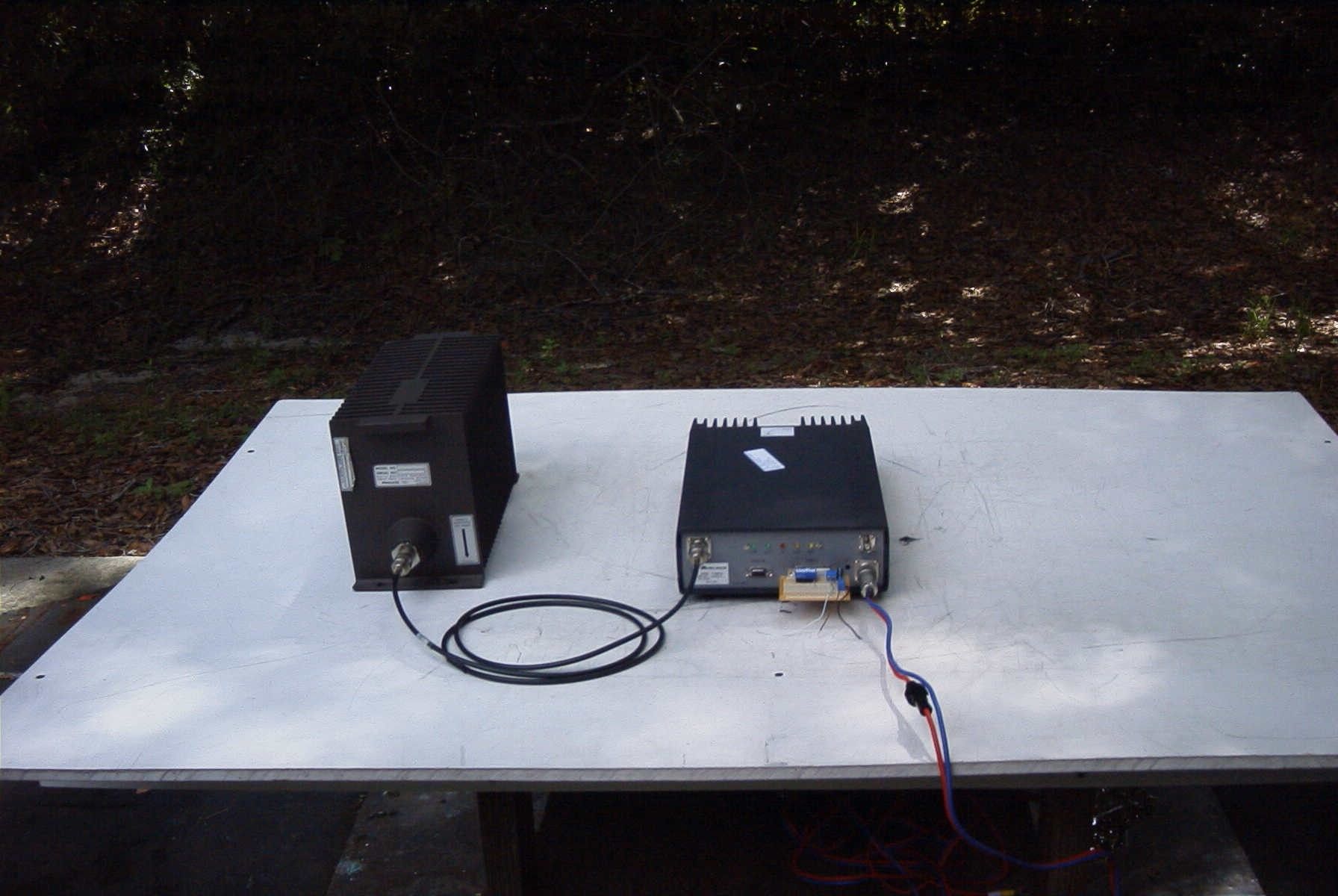
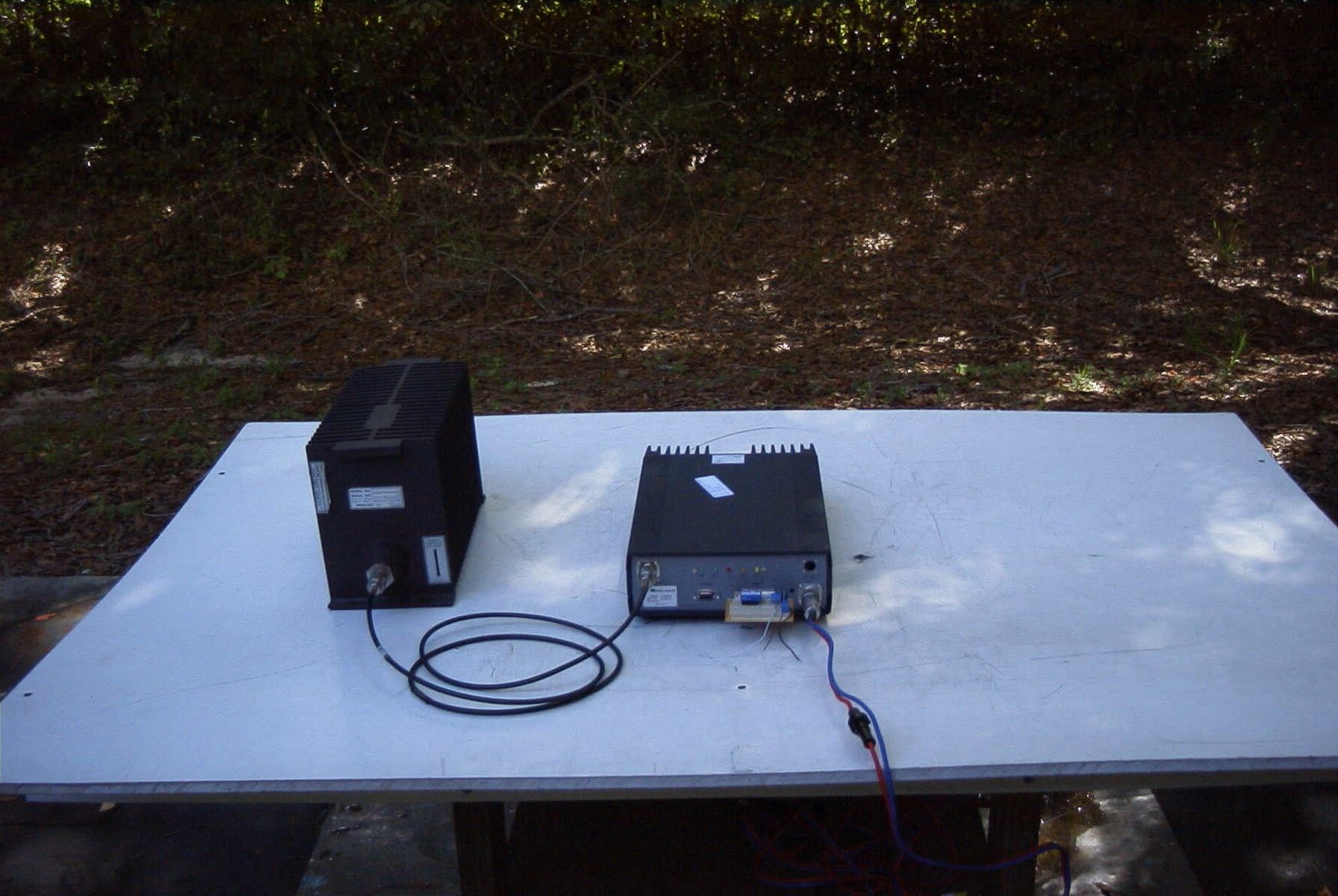
TIMCO ENGINEERING INC. 849 NW State Road 45 Newberry, Florida 32669 http://www.timcoengr.com 888.472.2424 F 352.472.2030 email: [email protected] APPLICANT: MIDLAND RADIO CORPORATION FCC ID: MMA7150610D REPORT #: V:\M\MidlandRadio_MMA\2123AUT6\2123AUT6 Test Report_Revised.doc COVER SHEET Test Report Product Name: UHF TRANSCEIVER FCC ID: MMA7150610D Applicant: MIDLAND RADIO CORPORATION 5900 PARRETTA DRIVE KANSAS CITY MO 64120 USA Date Receipt: 7/17/2006 Date Tested:8/14/2006 TIMCO ENGINEERING INC. 849 NW State Road 45 Newberry, Florida 32669 http://www.timcoengr.com 888.472.2424 F 352.472.2030 email: [email protected] APPLICANT: MIDLAND RADIO CORPORATION FCC ID: MMA7150610D REPORT #: V:\M\MidlandRadio_MMA\2123AUT6\2123AUT6 Test Report_Revised.doc TABLE OF CONTENTS TABLE OF CONTENTS LIST APPLICANT: MIDLAND RADIO CORPORATION FCC ID: MMA7150610D TEST REPORT: PAGE 1...........GENERAL INFORMATION & TECHNICAL DESCRIPTION PAGE 2...........TECHNICAL DESCRIPTION CONTINUED RF POWER OUTPUT PAGE 3...........MODULATION CHARACTERISTICS AUDIO FREQUENCY RESPONSE PLOT PAGE 4...........AUDIO LOW PASS FILTER PLOT PAGE 5-6.........MODULATION LIMITING PLOT PAGE 7-12........OCCUPIED BANDWIDTH PAGE 13-14.......SPURIOUS EMISSIONS AT ANTENNA TERMINALS PAGE 15-17.......FIELD STRENGTH OF SPURIOUS EMISSIONS PAGE 18..........METHOD OF MEASURING RADIATED SPURIOUS EMISSIONS PAGE 19..........FREQUENCY STABILITY PAGE 20-25.......TRANSIENT FREQUENCY STABILITY PAGE 26-27.......TEST SET UP PHOTOS PAGE 28..........EQUIPMENT LIST EXHIBITS CONTAING: SCHEMATIC DIAGRAM PARTS LIST OPERATING MANUAL SERVICE MANUAL LABEL SAMPLE LABEL LOCATION EXTERNAL PHOTOGRAPHS INTERNAL PHOTOGRAPHS TUNING PROCEDURE OPERATIONAL DESCRIPTION TEST SET UP PHOTOGRAPHS TIMCO ENGINEERING INC. 849 NW State Road 45 Newberry, Florida 32669 http://www.timcoengr.com 888.472.2424 F 352.472.2030 email: [email protected] APPLICANT: MIDLAND RADIO CORPORATION FCC ID: MMA7150610D REPORT #: M\MidlandRadio_MMA\2123AUT6\2123AUT6TestReport.doc Page 1 of 28 GENERAL INFORMATION REQUIRED FOR CERTIFICATION OF A LICENSED TRANSMITTER Part 2.1033(c)(1)(2) MIDLAND RADIO CORPORATION will manufacture the FCCID: MMA7150610D UHF TRANSCEIVER in quantity, for use under FCC RULES PART 90. Part 2.1033(c) TECHNICAL DESCRIPTION Part 2.1033(c)(3) Instruction book. A draft copy of the instruction manual is included as an exhibit. Part 2.1033(c) (4) Type of Emission: 10K6F3E Part 90.209 Part 90.207 Bn = 2M + 2DK M = 3000 D = 2300 Bn = 2(3000)+2(2300) = 10.6k narrow 12.5 kHz Part 2.1033(c) (4) Type of Emission: 14K8F3E Part 90.207 Bn = 2M + 2DK M = 3000 D = 4400 Bn = 2(3000)+2(4400) = 14.8k wide 25 kHz Part 2.1033(c) (4) Type of Emission: 11K25F1D Part 90.207 Bn = 2M + 2DK M = N/2=4800 D = 825 Bn = 2(4800)+2(825) = 11.25k narrow 12.5 kHz Part 2.1033(c) (4) Type of Emission: 20K0F1D Part 90.207 Bn = 2M + 2DK M = N/2=9600 D = 400 Bn = 2(9600)+2(400) = 20.0k wide 25 kHz Part 2.1033(c)(5) Frequency Range: 440 - 475 MHz Part 90.209 (b)(5) Part 2.1033(c)(6)(7) Power Output shall not exceed 59 Watts into a 50 ohm Part 90.205 resistive load. There are no user power controls. TIMCO ENGINEERING INC. 849 NW State Road 45 Newberry, Florida 32669 http://www.timcoengr.com 888.472.2424 F 352.472.2030 email: [email protected] APPLICANT: MIDLAND RADIO CORPORATION FCC ID: MMA7150610D REPORT #: M\MidlandRadio_MMA\2123AUT6\2123AUT6TestReport.doc Page 2 of 28 Part 2.1033(c)(8) DC Voltages and Current into Final Amplifier: POWER INPUT: FINAL AMPLIFIER ONLY INPUT POWER – (13.6V)(4A) = 54 Watts Part 2.1033(c)(9) Tune-up procedure. The tune-up procedure is included as an exhibit. Part 2.1033(c)(10) Complete Circuit Diagrams: Circuit and block diagrams are included as exhibits. Part 2.1033(c)(10): Description of all circuitry and devices provided for determining and stabilizing frequency is included in the circuit description. Part 2.1033(c)(11): A photograph or drawing of the equipment identification label is included as an exhibit. Part 2.1033(c)(12): Photographs of the equipment of sufficient clarity to reveal equipment construction and layout and label location are included as an exhibit. Part 2.1033(c)(13): For equipment employing digital modulation, a detailed description of the modulation technique. This UUT uses FSK to modulate the transmitter. Part 2.1033(c)(14): The data required for 2.1046 through 2.1057 is submitted below. Part 2.1046(a) RF POWER OUTPUT RF power is measured by connecting a 50-ohm, resistive wattmeter to the RF output connector. With a nominal battery voltage, and the transmitter properly adjusted the RF output measures: OUTPUT POWER: HIGH – 11 Watts LOW - 6.5 Watts TIMCO ENGINEERING INC. 849 NW State Road 45 Newberry, Florida 32669 http://www.timcoengr.com 888.472.2424 F 352.472.2030 email: [email protected] APPLICANT: MIDLAND RADIO CORPORATION FCC ID: MMA7150610D REPORT #: M\MidlandRadio_MMA\2123AUT6\2123AUT6TestReport.doc Page 3 of 28 Part 2.1047(a)(b) Modulation characteristics: AUDIO FREQUENCY RESPONSE The audio frequency response was measured in accordance with TIA/EIA 603. A curve or equivalent data showing the frequency response of the audio modulating circuit over a range of 100 – 5000Hz shall be submitted. The audio frequency response curve is shown below. AUDIO FREQUENCY RESPONSE PLOT 08/09/06 14:28:272123AUT6 AUDIO FREQ RESPONCE PLOT Ma xFre q .a t1 ColorLine StyleThickDataAxisCursor1 CyanSolid1Anlr.Level A!Norm alizeLeft.. -15 +10 -10 -5 +0 +5 d B 1005k200300 400600 800 1k2k3k 1002.60071k Hz dx=2.50071 kHz TIMCO ENGINEERING INC. 849 NW State Road 45 Newberry, Florida 32669 http://www.timcoengr.com 888.472.2424 F 352.472.2030 email: [email protected] APPLICANT: MIDLAND RADIO CORPORATION FCC ID: MMA7150610D REPORT #: M\MidlandRadio_MMA\2123AUT6\2123AUT6TestReport.doc Page 4 of 28 Part 2.1047(a) Voice modulated communication equipment: For equipment required to have an audio low-pass filter, a curve showing the frequency response of the filter, or of all the circuitry installed b…
Text truncated - open the document above for the full version.
Contact Information
Applicant
Butch Rittmann(Director of Operations)
Test Firm
Timco Engineering, Inc.Sid Sanders
Technical Specifications
| # | Rule Parts | Frequency Range | Power Output | Emission | Tolerance |
|---|---|---|---|---|---|
| 8 | 9 | 440 MHz - 475 MHz | 6.5 W | 20K0F1D | 1.5 ppm |
Other Applications from Midland Radio Corporation

MMAMXMC95
Jun 10, 2026Wireless Bluetooth Microphone
Equipment Class
JAB - Part 15 Class B Digital Device
MMAMXT295
Jun 08, 2026GMRS Radio
Equipment Class
TNF - Licensed Non-Broadcast Transmitter Held to Face
MMACLIPTALK
Apr 27, 2026Transceiver
Equipment Class
DTS - Digital Transmission System
MMABR200S
Jan 13, 2026BUSINESS BAND TWO-WAY RADIO
Equipment Class
TNF - Licensed Non-Broadcast Transmitter Held to Face
MMAGXT67
Oct 29, 2023GMRS RADIO
Equipment Class
TNF - Licensed Non-Broadcast Transmitter Held to Face