MMA75517
Midland Radio Corporation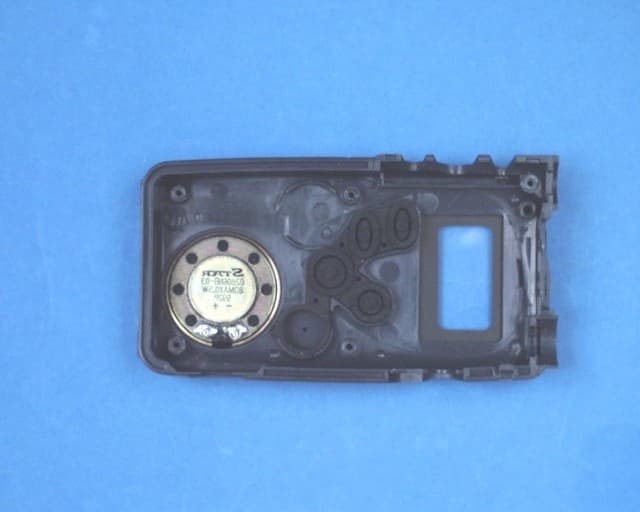
Click to zoom
Application Details
- Equipment Class
- FRF - Part 95 Family Radio Face Held Transmitter
- Date of Grant
- Mar 02, 2000
- Application Purpose
- Original Equipment
- Date of Application
- Feb 22, 2000
- Frequency Range
- 462.56250000 - 467.71250000
- Company
- Midland Radio Corporation
- Country
- United States
Documents & Files
Document Text
Text extracted from the exhibit documents filed with the FCC. Open a document above to read the original.
Users Manual
2 TABLE OF CONTENTS TIPS FOR GETTING THE MOST FROM YOUR 75-517........................................... 3 A NOTE ABOUT THE CTCSS or DCS CODES..................................................... 4 PREPARATION........................................................................................................... 4 BATTERIES............................................................................................................. 4 CHARGING THE BATTERIES............................................................................... 5 BELT CLIP............................................................................................................... 5 QUICK USE INSTRUCTIONS: ................................................................................... 5 POWER SAVE CIRCUIT............................................................................................. 5 RANGE OF FRS RADIOS........................................................................................... 5 FEATURES AND LOCATION OF CONTOLS........................................................... 6 TURNING THE RADIO ON OR OFF ..................................................................... 6 LOCKING THE CONTROLS .................................................................................. 6 UNLOCKING THE CONTROLS ............................................................................. 6 SELECTING THE CHANNEL................................................................................. 6 ADJUSTING THE VOLUME................................................................................... 7 ADJUSTING THE SQUELCH ................................................................................. 7 USING THE CALL FUNCTION .............................................................................. 7 USING THE MONITOR FUNCTION ...................................................................... 7 TURNING ON OR OFF THE BUTTON PRESS BEEP........................................... 7 TURNING ON THE DISPLAY BACKLIGHT......................................................... 7 TURNING THE ROGER BEEP ON OR OFF.......................................................... 7 LISTENING TO WEATHER BROADCASTS......................................................... 8 ACTIVATING SCAN FUNCTIONS ........................................................................ 8 ACTIVATING DUAL WATCH ............................................................................... 9 ACTIVATING “PRIVACY” CODES..................................................................... 10 DCS CODES .......................................................................................................... 11 RESETTING THE RADIO..................................................................................... 11 OPERATING THE HANDS FREE VOX (VOICE OPERATED TRANSMIT)..... 12 SETTING BABY SITTER MODE......................................................................... 13 SETTING MEMORY CHANNELS....................................................................... 14 ACCESSING MEMORY CHANNELS.................................................................. 14 DISPLAY SYMBOLS ............................................................................................ 15 TROUBLESHOOTING.............................................................................................. 16 CARE OF RECHARGEABLE NI-CAD BATTERIES............................................... 17 SERVICE: .................................................................................................................. 18 TECHNICAL SPECIFICATIONS* ............................................................................ 19 LIMITED WARRANTY............................................................................................. 20 OPTIONAL ACCESSORIES FOR YOUR RADIO 3 Accessory Name Model Number Ni-cad Battery (single “AA” 3 required)..................................18-BATT Standard Charger............................................................18-396 Quick Charger................................................................18-389 Charger Stand ...............................................................18-383 Lapel Microphone with Ear-bud Speaker...............................22-405 Speaker/Microphone........................................................22-411 Boom Microphone Headset ..............................................22-540 Call 816 241 8500 ext. 200 to order accessories. THIS RADIO COMPLIES WITH PART 15 OF THE FCC RULES. OPERATION IS SUBJECT TO THE CONDITION THAT THIS DEVICE DOES NOT CAUSE HARMFUL INTERFERENCE. Your Midland model 75-517 brings the new FRS (Family Radio Service) to your fingertips. The Family Radio Service is provided for by the FCC and is totally license free. For the first time business and the general public can use the quiet UHF FM band for personal communications at no air time charge. The 75-517 uses maximum allow able pow er for range up to 2 miles. Use for fishing, hunting, picnics, biking, business, or any other activity where communications are needed for convenience or safety. The model 75-517 incorporates all 14 channels with 38 different CTCSS and 83 DCS codes to provide the best in quiet communications. Also this radio offers scan, power save, 9 memory channels and a multifunction back-lighted liquid crystal display. This unit also incorporates VOX (voice operated transmit) that allows hands free use when the radio is equipped with certain accessories. TIPS FOR GETTING THE MOST FROM YOUR 75-517 Due to the band of operation (462/467 MHz) the 75-517 provides communications that are virtually free of atmospheric interference (skip) that is common on lower frequency bands. Along with this and an antenna system that is very efficient as compared to other unlicensed radio bands, communications range is surprisingly good. Many times the limit to maximum possible range is environmental factors such as …
Text truncated - open the document above for the full version.
Internal Photos
Mother & Daughter Boards w/Shields Daughter Board A Mother Board Daughter Board B Daughter Board A W/O Shield Daughter Board B W/O Shield Rear of Mother Board Speaker Housing
Test Report
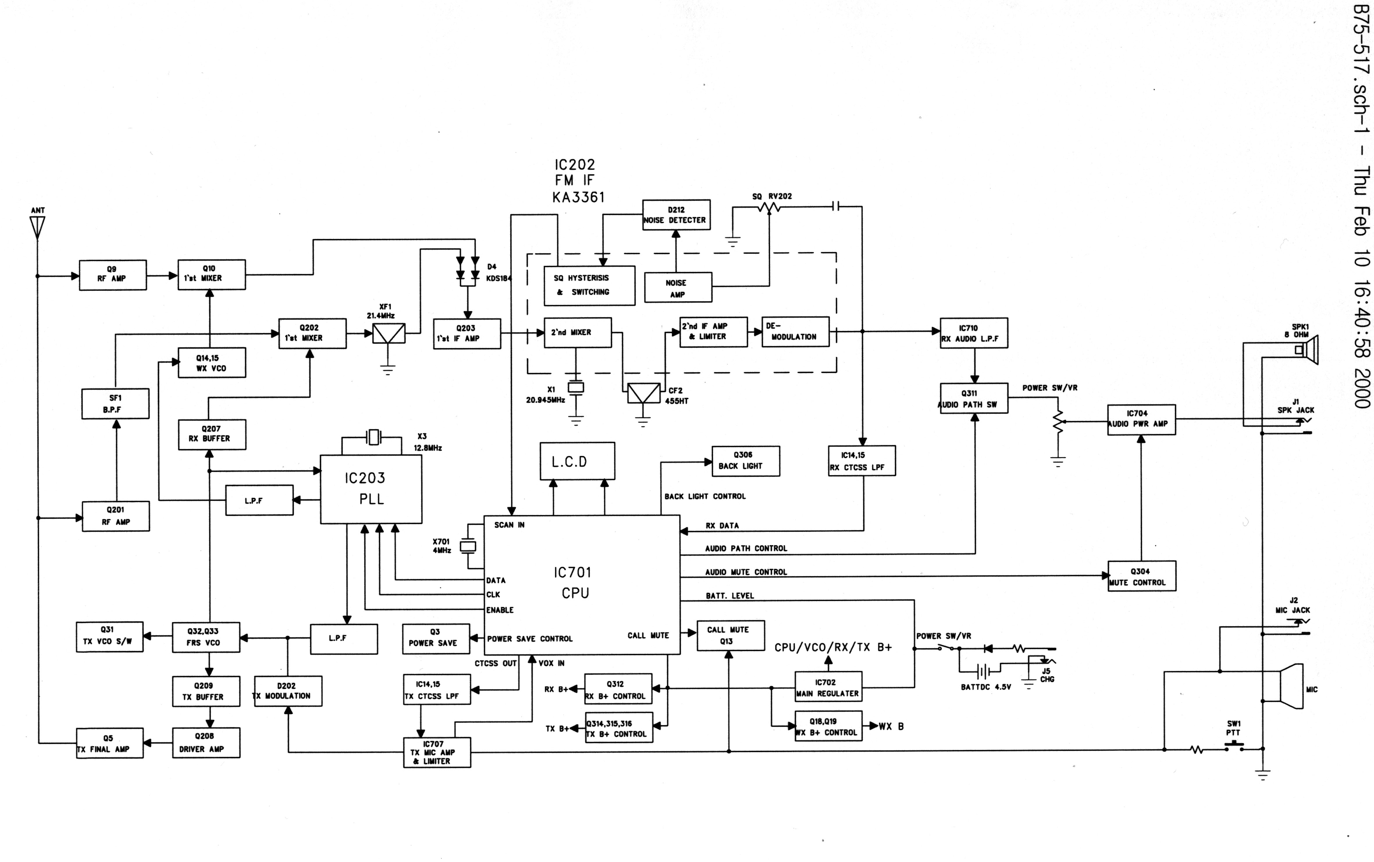
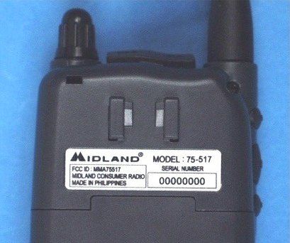
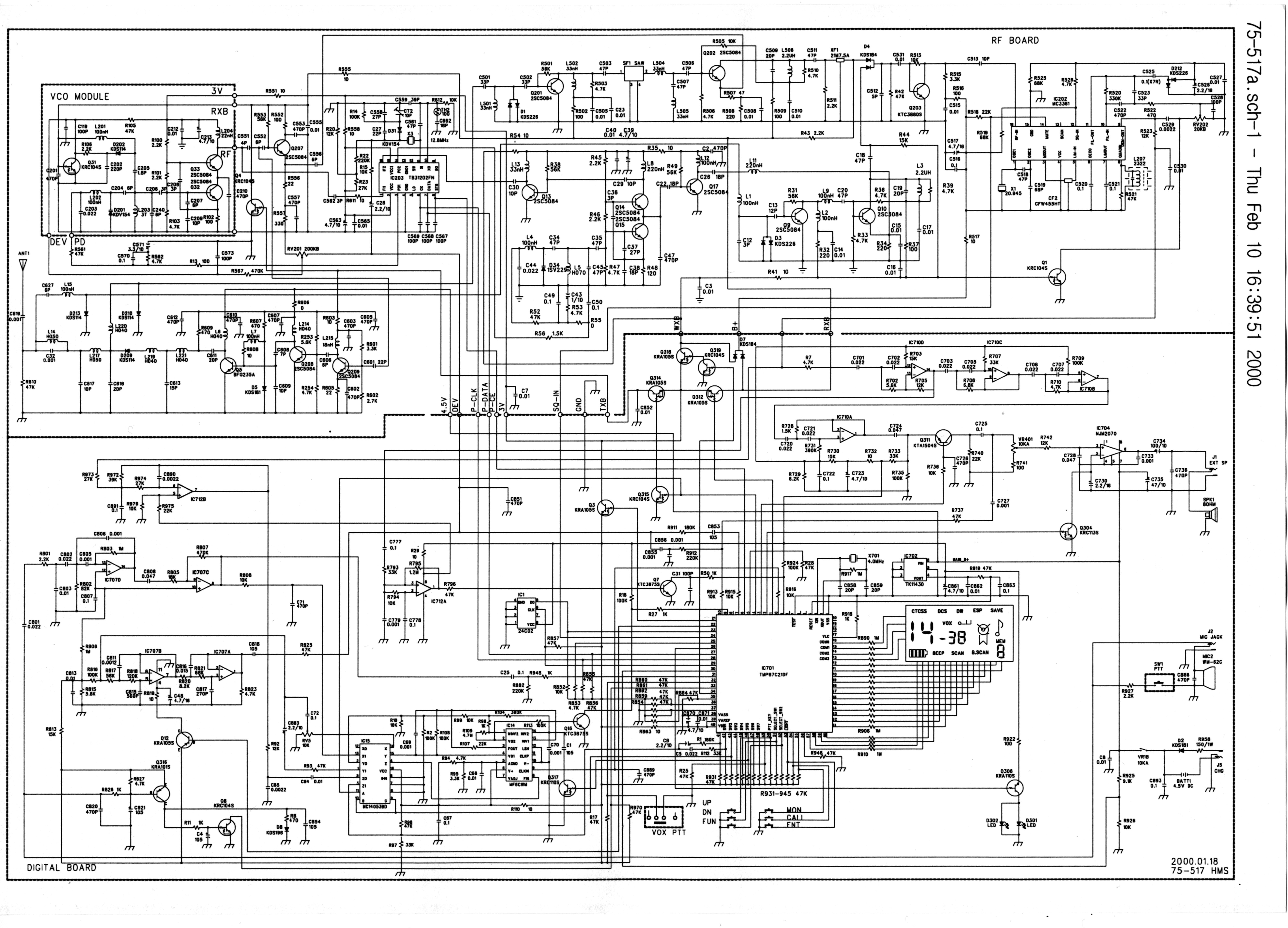
ENGINEERING STATEMENT For Type Certification of Midland Consumer Radio Model No: 75-517 FCC ID: MMA75517 I am an Electronics Engineer, a principal in the firm of Hyak Laboratories, Inc., Springfield, Virginia. My education and experience are a matter of record with the Federal Communications Commission. Hyak Laboratories, Inc. has been authorized by Midland Consumer Radio to make type certification measurements on the 75- 517 transceiver. These tests made by me or under my supervision in our Springfield laboratory. Test data and documentation required by the FCC for Type Certification are included in this report. The data verifies that the above mentioned transceiver meets FCC requirements and Type Certification is requested. ______________________________ Rowland S. Johnson Dated: February 22, 2000 A. INTRODUCTION The following data are submitted in connection with this request for type certification of the 75-517 transceiver in accordance with Part 2, Subpart J of the FCC Rules. The 75-517 is a portable, battery operated, UHF, frequency modulated transceiver intended for 12.5 kHz channel family radio service applications in the 462.5625-467.7125 MHz band. It operates from a nominal 4.5 Vdc battery supply. MFR rated output power is 0.5 watts ERP. B. GENERAL INFORMATION REQUIRED FOR TYPE CERTIFICATION (Paragraph 2.983 of the Rules) 1. Name of applicant: Midland Consumer Radio 2. Identification of equipment: FCC ID: MMA75517 a. The equipment identification label is submitted as a separate exhibit. b. Photographs of the equipment are submitted as a separate exhibit. 3. Quantity production is planned. 4. Technical description: a. 11k0F3E emission b. Frequency range: 462.5625 - 467.7125 MHz. c. Operating power of transmitter is fixed at the factory at less than 0.5 W ERP. d. Maximum power permitted is 0.5 watts, and the 75-517 fully complied with that power limitation. e. The dc voltage and dc currents at final amplifier: Collector voltage: 4.4 Vdc Collector current: 0.50 A f. Function of each active semiconductor device: See Appendix 1. g. Complete schematic diagram is submitted as a separate exhibit. h. A draft instruction manual is submitted as a separate exhibit. i. The transmitter tune-up procedure is submitted as a separate exhibit. 2 B. GENERAL INFORMATION (continued) j. A description of circuits for stabilizing frequency is included in Appendix 2. k. A description of circuits and devices employed for suppression of spurious radiation and for limiting modulation is included in Appendix 3. l. Not applicable. 5. Data for 2.985 through 2.997 follow this section. C. RF_Power_Output (Paragraph 2.985(a) of the Rules) The 75-517 has a permanently attached built-in antenna without provisions for a coaxial connector. Therefore RF power output was calculated, see Table 1. (The transmitter was tuned by the factory. TABLE 1 Operating Freq., MHz Power watts into a dipole antenna 462.5625 0.481 D. MODULATION CHARACTERISTICS 1. A curve showing frequency response of the transmitter is shown in Figure 1. Reference level was audio signal output from a Boonton 8220 modulation meter with one kHz deviation. Audio output was measured with an Audio Precision System One integrated test system. 2. Modulation limiting curves are shown in Figure 2, using a Boonton 8220 modulation meter. Signal level was established with a Audio Precision System One integrated test system. The curves show compliance with paragraphs 2.987(b). 3. Figure 3 is a graph of the post-limiter low pass filter which provides a roll-off of 60Logf/3 dB where f is audio frequency in kHz. Measurements were made following EIA RS-152B with an Audio Precision System One integrated test system on the Boonton 8220 modulation meter audio output. 3 4. Occupied_Bandwidth (Paragraphs 2.989(c) of the Rules) Figure 4 is a plot of the sideband envelope of the transmitter output taken with a Tektronix 494P spectrum analyzer. Modulation corresponded to conditions of 2.989(c)(1) and consisted of 2500 Hz tone at an input level 16 dB greater than that necessary to produce 50% modulation at 2722 Hz, the frequency of maximum response. Measured modulation under these conditions was 1.6 kHz. Emission designator: (2M + 2D) (2 x 3 kHz) + (2 x 2.5 kHz) = 11k0F3E 4 FIGURE 1 MODULATION FREQUENCY RESPONSE MODULATION FREQUENCY RESPONSE FCC ID: MMA75517 FIGURE 1 5 FIGURE 2 AUDIO LIMITER CHARACTERISTICS AUDIO LIMITER CHARACTERISTICS FCC ID: MMA75517 FIGURE 2 6 FIGURE 3 AUDIO LOW PASS FILTER RESPONSE AUDIO LOW PASS FILTER RESPONSE FCC ID: MMA75517 FIGURE 3 7 FIGURE 4 OCCUPIED BANDWIDTH ATTENUATION IN dB BELOW MEAN OUTPUT POWER Required On any frequency more than 50% up to and including 100% of the 25 authorized bandwidth, 12.5 kHz (6.25-12.5 kHz) On any frequency more than 100%, up to and including 250% of the 35 authorized bandwidth (12.5-31.25 kHz) On any frequency removed from the assigned frequency by more 43+10LogP = 40 than 250% of the authorized (P = 0.481) bandwidth (over 31.25 kHz) OCCUPIED BANDWIDTH FCC ID: MMA75517 FIGURE 4 8 D. MODULATION CHARACTERISTICS (Continued) The plots are within FCC limits. The horizontal scale frequency) is 10 kHz per division and the vertical scale amplitude) is a logarithmic presentation equal to 10 dB per division. E. SPURIOUS EMISSIONS AT THE ANTENNA TERMINALS (Paragraph 2.991 of the Rules) The 75-517 has a permanently attached antenna. There is no connector for an external antenna. Therefore, no antenna terminal conducted measurements were made. F. DESCRIPTION OF RADIATED SPURIOUS MEASUREMENT FACILITIES A description of the Hyak Laboratories’ radiation test facility is a matter of record with the FCC. The facility was accepted for radiation measurements from 25 to 1000 MHz on October 1, 1976 and is currently listed as an accepted site. G. FIELD STRENGTH MEASUREMENTS OF SPURIOUS RADIATION Field intensity measurements of radiated spurious emissions from the 75-517 were made with a Tektronix 494P spectrum analyzer using Singer DM-105 …
Text truncated - open the document above for the full version.
Contact Information
Applicant
Butch Rittmann(Director of Operations)
Technical Contact
Hyak Laboratories, Inc.Rowland S Johnson
[email protected](703) 451-1188
7011 Calamo St., Suite 107 · Springfield, Virginia · United States
Non-Technical Contact
Hyak Laboratories, Inc.Georgia Hall
[email protected](703) 451-1188
Test Firm
Hyak Laboratories, Inc.Rowland Johnson
703-451-1188
Technical Specifications
| # | Rule Parts | Frequency Range | Power Output | Emission | Tolerance |
|---|---|---|---|---|---|
| 1 | 95B | 462.5625 MHz - 467.7125 MHz | 500.00 mW | 11k0F3E | 0.0002500000 % |
Other Applications from Midland Radio Corporation

MMAMXMC95
Jun 10, 2026Wireless Bluetooth Microphone
Equipment Class
JAB - Part 15 Class B Digital Device
MMAMXT295
Jun 08, 2026GMRS Radio
Equipment Class
TNF - Licensed Non-Broadcast Transmitter Held to Face
MMACLIPTALK
Apr 27, 2026Transceiver
Equipment Class
DTS - Digital Transmission System
MMABR200S
Jan 13, 2026BUSINESS BAND TWO-WAY RADIO
Equipment Class
TNF - Licensed Non-Broadcast Transmitter Held to Face
MMAGXT67
Oct 29, 2023GMRS RADIO
Equipment Class
TNF - Licensed Non-Broadcast Transmitter Held to Face