MMA77104XLCB Transmitter
Midland Radio Corporation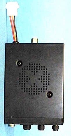
Click to zoom
Application Details
- Equipment Class
- TNB - Licensed Non-Broadcast Station Transmitter
- Date of Grant
- May 11, 2000
- Application Purpose
- Original Equipment
- Date of Application
- Apr 17, 2000
- Equipment Note
- CB Transmitter
- Frequency Range
- 26.96500000 - 27.40500000
- Company
- Midland Radio Corporation
- Country
- United States
Documents & Files
Document Text
Text extracted from the exhibit documents filed with the FCC. Open a document above to read the original.
External Photos
Front View Back View Top View Botto m View
Internal Photos
Circuit Board, Track Side PLL Top PLL Bottom Circuit Board, Component Side Circuit Board, Component Side PLL Top
Operational Description
ALIGNMENT INSTRUCTIONS Warning : Any repairs or adjustment should be made under the supervision of a qualified radiotelephone technician. 8.1. VCO a. Connect the power supply (DC 13.8 V) b. Connect the oscilloscope probe to test point C84 c. Adjust the coil T7 for 3.8V at 40-Ch RX. d. Check that T6 voltmeter of receiver reads from 2 to 4 volts for all channels. 8.2. Transmitter a. TX Power alignments With RF voltmeter at base of Q24, transmit of channel 19. Adjust in turn T8, T9 for maximum reading on RF voltmeter. Repeat as needed. Remove RF voltmeter. b. Max Mod Alignments Adjust VR4 to obtain 90% MOD. At 16 dB greater than 50% MOD. AF 1 kHz. c. Final Check 1. Output power should be from 3.6 to 4.0 watts. 2. Frequency should be within +400 Hz of channel center frequency. 3. Spurious content as observed on spectrum synthesizer should be at least 60 dB below carrier. 4. With 2500 Hz modulation at 16 dB greater than that required to produce 50% modulation, occupied bandwidth should be at least 2 dB better than limit spec. 8.3. RX Sensitivity Alignment a. Set the signal generator to provide 27.185 MHz, 1 kHz 30% modulation. Place the channel selector in channel 19 position. b. Adjust T1, T2, T3, T4, and T5 for maximum audio output across the 8 ohm dummy load resistor. This alignment should be performed by gradually decreasing the signal output signal to a minimum level required for tuning to avoid inaccurate alignment due to AGC action. Squelch Circuit Alignment a. Set the signal generator to provide 60 dB, 1 kHz, 30% mod antenna input. b. Rotate the squelch control in full clockwise direction. c. Temporarily adjust for maximum audio output, and note the audio output level. Then adjust so that audio output just appeared. d. Next, reduce the antenna input signal level to 53~58 dB and make sure the audio output decreases to zero. e. Reduce antenna signal input level to zero, and adjust the SQ control until the noise output decreases to just disappear.
Test Report
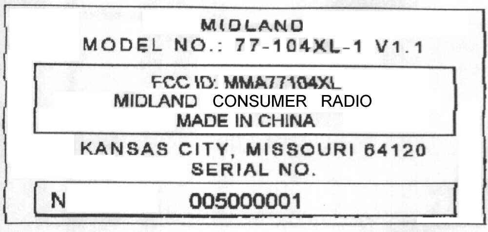
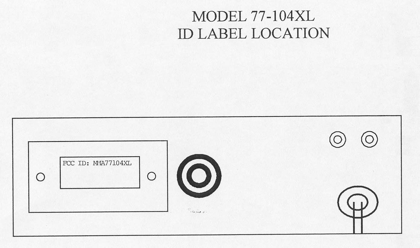
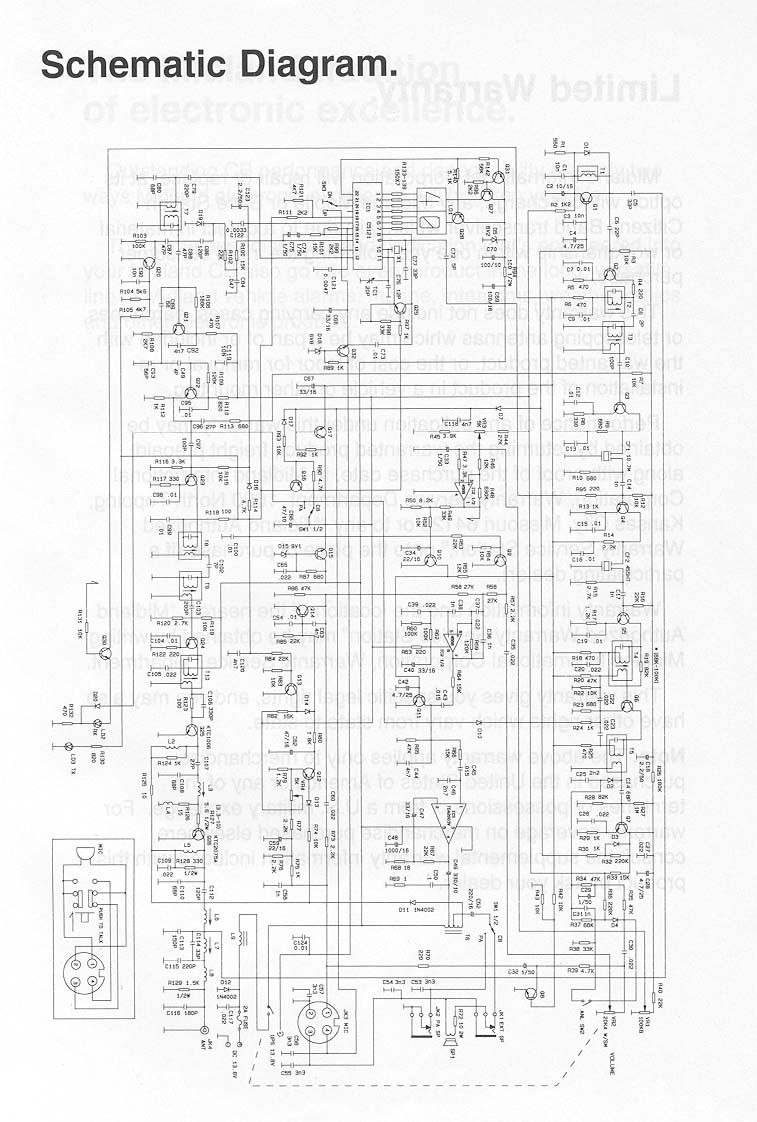
ENGINEERING STATEMENT For Type Certification of MIDLAND CONSUMER RADIO Model No: 77-104XL FCC ID: MMA77104XL I am an Electronics Engineer, a principal in the firm of Hyak Laboratories, Inc., Springfield, Virginia. My education and experience are a matter of record with the Federal Communications Commission. Hyak Laboratories, Inc. has been authorized by Midland Consumer Radio to make type certification measurements on the 77- 104XL transceiver. These tests were made by me or under my supervision in our Springfield laboratory. Test data and documentation required by the FCC for type certification are included in this report. It is submitted that the above-mentioned transceiver meets all applicable FCC require- ments. ______________________________ Rowland S. Johnson Dated: April 12, 2000 A. INTRODUCTION The following data are submitted in connection with this request for type certification of the 77-104XL transceiver in accordance with Part 2, Subpart J of the FCC Rules. The 77-104XL is a double-sideband amplitude modulated transmitter/receiver combination intended for mobile operation in the citizens radio service. The transmitter has 40-channel capability in the 26.965 - 27.405 MHz band utilizing phase locked loop (PLL) technology. B. GENERAL INFORMATION REQUIRED FOR TYPE ACCEPTANCE (Paragraph 2.983 of the Rules) 1. Name of applicant: Midland Consumer Radio 2. Identification of equipment: FCC ID: MMA77104XL a. The equipment identification label is submitted as a separate exhibit. Photographs of the equipment are submitted as a separate exhibit. 3. Quantity production is planned. 4. Technical description: a. 6k00A3E emission b. Frequency range: 26.965 - 27.405 MHz c. Operating power of transmitter is fixed at the factory at less than 4 watts, AM. d. Maximum power rating under 95.635(c) of the Rules is 4 watts. e. The dc voltage and dc currents at final amplifier: Collector voltage: 13.7 V Collector current: 611 mA @ 13.8 Vdc. f. Function of each active semiconductor device: See Appendix 1. g. Complete circuit diagram is submitted as a separate exhibit. A draft instruction book is submitted as a separate exhibit. The transmitter tune-up procedure is submitted as a separate exhibit. j. A description of circuits for stabilizing frequency is included in Appendix 2. k. A description of circuits and devices employed for suppression of spurious radiation and for limiting modulation is included in Appendix 3. l. Not applicable. 2 B. GENERAL INFORMATION...(Continued) 5. Data for 2.985 through 2.997 follow this section. 6. RF_Power_Output (Paragraph 2.985(a),(b)(1) of the Rules) RF power output in the AM mode was measured with a Bird 4421 RF power meter and a Narda 765-20 50 ohm dummy load. (The transmitter was tuned by the factory.) Power was measured with a supply voltage of 13.8 Vdc and indicated: Channel Power, watts 1 4.0 21 4.0 40 4.0 B. MODULATION CHARACTERISTICS 1. AF_Frequency_Response A curve showing frequency response of the transmitter is shown in Figure 1. Reference level was taken as a 1 kHz tone with 50% modulation, as measured on a Datatech 209 modulation meter, using a Audio Precision TRMS voltmeter and tracking generator. 2. Modulation_Limiting Curves of AM modulation limiting for both positive and negative peaks are shown in Figures 2a and 2b, respec- tively. Characteristics at 300, 830, and 2500 Hz are shown using a Datatech 209 modulation meter. Signal level was established with a Audio Precision TRMS voltmeter and tracking generator. The curves show compliance with Paragraph 95.633(d) of the Rules. 3. Modulation_Limiter_Attack_Time Modulation limiter attack time was measured by applying to the microphone input terminals a pulsed tone at 2500 Hz, 16 dB above the level required for 50% modulation at the frequency of maximum response, 830 Hz. The spectrum analyzer was tuned to upper and lower fourth- order sidebands in the time domain. Sweep speed was 100 milliseconds per division. Plots are included as Figures 3a and 3b. Any transients observed in excess of 33 dB attenuation as referenced to the carrier were less than 20 ms in duration. 3 FIGURE 1 TRANSMITTER FREQUENCY RESPONSE TRANSMITTER FREQUENCY RESPONSE FCC ID: MMA77104XL FIGURE 1 4 FIGURE 2a AM MODULATION LIMITING - POSITIVE PEAKS MODULATION LIMITING CHARACTERISTICS Percent modulation as a function of input level at microphone jack in dBm for 300 Hz, 830 Hz, and 2500 Hz tones. MODULATION LIMITING POSITIVE PEAKS FCC ID: MMA77104XL FIGURE 2a 5 FIGURE 2b AM MODULATION LIMITING - NEGATIVE PEAKS MODULATION LIMITING CHARACTERISTICS Percent modulation as a function of input level at microphone jack in dBm for 300 Hz, 830 Hz, and 2500 Hz tones. MODULATION LIMITING NEGATIVE PEAKS FCC ID: MMA77104XL FIGURE 2b 6 FIGURE 3a MODULATION LIMITER ATTACK TIME Measurement_Conditions: 16 dB over 50% modulation level at 830 Hz with 2500 Hz tone, upper fourth order sideband; horizontal scale 100 ms/div. UPPER FOURTH-ORDER SIDEBAND LIMITER ATTACK TIME FCC ID: MMA77104XL FIGURE 3a 7 FIGURE 3b MODULATION LIMITER ATTACK TIME Measurement_Conditions: 16 dB over 50% modulation level at 830 Hz with 2500 Hz tone, lower fourth order sideband; horizontal scale 100 ms/div. LOWER FOURTH-ORDER SIDEBAND LIMITER ATTACK TIME FCC ID: MMA77104XL FIGURE 3b 8 C. MODULATION CHARACTERISTICS (Continued) 4. Occupied_Bandwidth_-_AM (Paragraph 2.989(c) of the Rules) Figure 4 is a plot of the sideband envelope of the transmitter taken from a Tektronix 494P spectrum ana- lyzer. Modulation corresponded to conditions of 2.989(a) and consisted of 2500 Hz tone at an input level 16 dB greater than that necessary to produce 50% modulation at 830 Hz, the frequency of maximum response. Measured modulation at 1150 Hz was 85% positive, 86% negative. The plot is within the limits imposed by Paragraph 95.631(b)(1,3) for double sideband AM modulation. The horizontal scale, frequency, is 10 kHz per division and the vertical scale, amplitude, is a logarithmic presen- tation equal to 10 …
Text truncated - open the document above for the full version.
Contact Information
Applicant
Butch Rittmann(Director of Operations)
Technical Contact
Hyak Laboratories, Inc.Rowland S Johnson
[email protected](703) 451-1188
7011 Calamo St., Suite 107 · Springfield, Virginia · United States
Non-Technical Contact
Hyak Laboratories, Inc.Georgia Hall
[email protected](703) 451-1188
Test Firm
Hyak Laboratories, Inc.Rowland Johnson
703-451-1188
Technical Specifications
| # | Rule Parts | Frequency Range | Power Output | Emission | Tolerance |
|---|---|---|---|---|---|
| 1 | 95D | 26.965 MHz - 27.405 MHz | 4 W | 6k00A3E | 0.0050000000 % |
Other Applications from Midland Radio Corporation

MMAMXMC95
Jun 10, 2026Wireless Bluetooth Microphone
Equipment Class
JAB - Part 15 Class B Digital Device
MMAMXT295
Jun 08, 2026GMRS Radio
Equipment Class
TNF - Licensed Non-Broadcast Transmitter Held to Face
MMACLIPTALK
Apr 27, 2026Transceiver
Equipment Class
DTS - Digital Transmission System
MMABR200S
Jan 13, 2026BUSINESS BAND TWO-WAY RADIO
Equipment Class
TNF - Licensed Non-Broadcast Transmitter Held to Face
MMAGXT67
Oct 29, 2023GMRS RADIO
Equipment Class
TNF - Licensed Non-Broadcast Transmitter Held to Face