MMA9001ZMOBILE CB TRANSCEIVER
Midland Radio Corporation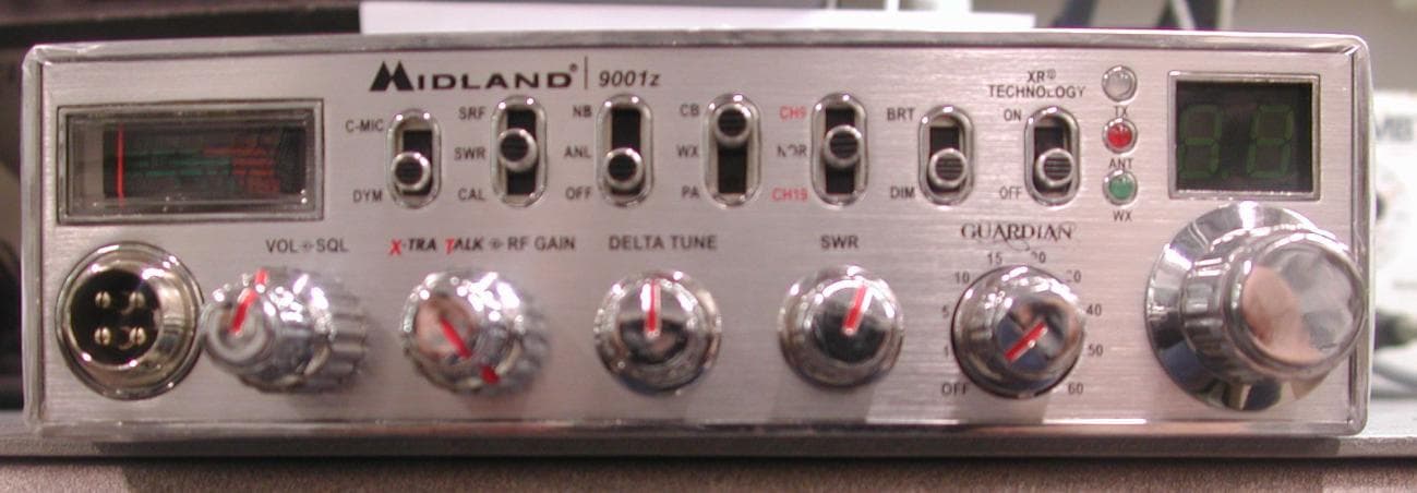
Click to zoom
Application Details
- Equipment Class
- TNB - Licensed Non-Broadcast Station Transmitter
- Date of Grant
- Dec 21, 2009
- Application Purpose
- Original Equipment
- Date of Application
- Dec 21, 2009
- Equipment Note
- MOBILE CB TRANSCEIVER
- Frequency Range
- 26.96500000 - 27.40500000
- Company
- Midland Radio Corporation
- Country
- United States
Documents & Files
Document Text
Text extracted from the exhibit documents filed with the FCC. Open a document above to read the original.
Users Manual
C l a s s i c C B R a d i o w i t h G u a r d i a n A l e r t W W W . M I D L A N D R A D I O . C O M Owner‘s Manual Midland Radio Corporation 5900 Parretta Drive Kansas City, MO. 64120 Tel. +1-816-241-8500 9001z www.midlandradio.com 1 9001z INDEX Thank You ................................................................................................................................................................................2 Major 9001z Features ...........................................................................................................................................................2 Installation ...........................................................................................................................................................................2-3 CB Antenna .............................................................................................................................................................................3 9001z Features and Controls .............................................................................................................................................4 Feature Operation .................................................................................................................................................................5 How to Operate Your CB ...................................................................................................................................................6 Technical Specifications ........................................................................................................................................................7 Limited Warranty ...................................................................................................................................................................7 Limitation of Liability ............................................................................................................................................................7 Service and Technical Support ........................................................................................................................................8 Accessories ........................................................................................................................................................................8 Accessories Order Form ................................................................................................................................................9 Other Midland Products ...............................................................................................................................................10 2 www.midlandradio.com Thank you Congratulations on your purchase of a state-of-the-art Midland 9001z mobile CB radio. In the years ahead, you can expect to realize time and again why Midland holds the front running position among CB users everywhere. You will come to know that American Original is not just a slogan, but the heading of long list of hearable, seeable benefits. As your Midland CB experience unfolds and grows we hope you will remember that CB radios are only one kind of electronic excellence available under the Midland name. Your 40 channel CB radio represents the state of the art in high tech engineering. The unit incorporates microprocessor con - trolled PLL circuitry for precise tuning. The 9001z is a classic style CB with the innovative Guardian alert feature that is skillfully constructed with the finest components.This radio is designed for reliable and trouble-free performance for years to come. Enjoy! Midland Radio Corporation Hereby certifies that this unit has been designed, manufactured, FCC type accepted and certified in accordance with part 95 and Part 15, Subpart C of the current FCC rules and regulations as of the date of manufacture. • 40 CB Channels • 4 Watt Output Power • Guardian Alert • Weather Scan • XTRA TALK Mic Control • Instant Channel 9/19 • RF Gain • Switchable Noise Blanker(NB) • Delta Tune • SWR Calibration • XR Technology • Automatic Noise Limiter(ANL) • PA Function • Last Channel Memory • Push to talk ergonomically designed microphone • 9 ft coil Mic cord • Includes mounting bracket/hardware and fuse DC power cord Major 9001z Features Installation This transceiver may be installed in any 12-volt negative ground-system car or truck. Most current U.S. and Foreign vehicles use a negative system, but some older models and some newer large trucks may have a positive ground. Check the requirements for your vehicle before you begin installation. Generally, you have a negative-ground system if the minus (-) battery terminal is connected to the motor block. Contact your dealer in the event you are unable to determine your vehicle’s polarity system. Location Your new Midland CB is designed to be installed under the dash or vertically on a console of your vehicle. Safety and convenience are the primary considerations in deciding exactly where to locate your radio. Caution: Be sure that the unit is located so that it does not interfere with the driver, supplemental restraint systems (air bags), or impair access to any controls. Connecting cables must be routed and secured in such a manner as not to interfere with the operation of the brake, accelerator or other controls. Interference from either the unit or connecting cables may contribute to the loss of control of the vehicle. Mechanical Mounting Step 1: Plug power cable into back of radio marked “Power”. Be sure to observe polarity markings. Step 2: Use the mounting bracket as a template for marking the location of screw holes under the dash. Use a nail or other sharp pointed object to mark the hole locations. Step 3: Drill a ‘1/8” hole for each screw hole in the mounting bracket. Attach the bracket to the dash with the Phillips head sheet metal screws provided. NOTE: Extreme care should be exercised when drilling…
Text truncated - open the document above for the full version.
Cover Letter(s)
5900 Parretta Drive ● KANSAS CITY, MISSOURI ● 64120 TELEPHONE: (816) 241-8500 ● FAX: (816) 241-5713 EMAIL: [email protected] WEBSITE: www.midlandradio.com Midland Radio Corporation 5900 Parretta Drive, Kansas City, MO. 64120 Phone: (816) 241-8500 Fax: (816) 241-5713 Website: wwwl.midlandradio.com E-Mail: [email protected] October 14, 2009 Federal Communications Commission Authorization and Evaluation Commission Confidentiality Request regarding application for certification of FCC ID: MMA9001Z Pursuant to Sections 0.457 and 0.459 of the Commission’s Rules, we hereby request confidential treatment of information accompanying this application as outlined below: Schematic Block Diagram Operational description The above materials contain trade secrets and proprietary information not customarily released to the public. The public disclosure of these materials may be harmful to the applicant and provide unjustified benefits to its competitors. The applicant understands that pursuant to Section 0.457 of the Rules, disclosure of this application and all accompanying documentation will be made before the date of the Grant for this application. Sincerely, David K. Free Engineering Project Manager
External Photos
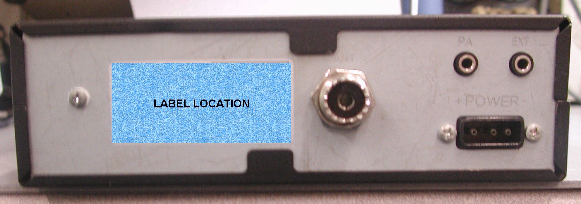
APPLICANT: MIDLAND RADIO CORP. FCC ID: MMA9001Z EXTERNAL PHOTOS
Internal Photos
APPLICANT: MIDLAND RADIO CORP. FCC ID: MMA9001Z INTERNAL PHOTOS
Parts List/Tune Up Info
GP214D 1.4GHz DUAL PLL DESCRIPTION The GP214D is a dual frequency synthesizer designed for RF operation up to 1.4GHz. The device contains prescalers, programmable reference, and feedback frequency dividers, phase detectors, and charge pumps necessary for the precision control of dual VCO loops. Data transfer is made via a simple serial data interface. The GP214D is fabricated using advanced CMOS process and available in a 16-pin TSSOP plastic package with 0.65mm pitch . FEATURES ▪ Two systems for transmitter and receiver Pb 16TSSOP ▪ 2.4V to 5.0V operation (100MHz to 1.4GHz) ▪ Low current consumption 8.5mA @ 3.0V (Typ.) ▪ Modulus prescaler, 64 / 66 ▪ Selectable charge pump current ± 0.2mA, ± 0.4mA, ± 0.8mA, ± 1.6mA APPLICATIONS ▪ Portable wireless communications (PCS, cordless) ▪ Other wireless communication systems BLOCK DIAGRAM Version 1.2 (Jan. 2006) 1GAINTECH INCORPORATED GP214D 1.4GHz DUAL PLL Version 1.2 (Jan. 2006) 2GAINTECH INCORPORATED PIN DESCRIPTION Pin No. Symbol Function Description I / O 1 Fin1 RF input, channel 1. I 2, 15 Vcc Power supply. Two pins are connected each other. - 3 CP1 Charge pump output, channel 1. Charge pump current is selected by the input serial data. O 4, 13 GND Ground. Two pins are connected. - 5 LD Output of lock detection. It is the open drain output. O 6 CK Clock input. 7 DATA Serial data input. 8 EN Input of enable signal. Serial data interface. I 9 BO Output of buffer amplifier. The local signal passes through the buffer amplifier. O 10 OSCO Oscillator output. O 11 OSCI PLL reference input. Typically connected to a TCXO output. I 12 SW Switchover terminal to control time constant of loop filter. It is the open drain output. When switched off, it’s normal output. O 14 CP2 Charge pump output, channel 2. O 16 Fin2 RF input, channel 2. I ABSOLUTE MAXIMUM RATINGS Parameters Symbol Value Unit Power supply voltage Vcc 5.5 V Operating temperature T OPR -30 to +85 °C Storage temperature T STG -35 to +150 °C ESD (Human body model) 2000 V Note: This device is ESD sensitive. Appropriate ESD protection is required for device handling and assembly. GP214D 1.4GHz DUAL PLL Version 1.2 (Jan. 2006) 3GAINTECH INCORPORATED ELECTRICAL CHARACTERISTICS (Unless otherwise specified, Vcc = 3.0V, Ta = 25°C) Characteristic Symbol Test Condition Min. Typ. Max.Unit Operating power supply voltage Vcc Fin1= Fin2= 200MHz~1.4GHz 2.4 3.0 5.0 V Operating current consumption Icc Fin1= Fin2= 800MHz/ -5dBm input 7.0 8.5 14.5mA Standby current I SB Standby mode - 0 80 μA Fin operating frequency Fin Fin1=Fin2= -5dBm 200 - 1400MHz Vcc = 2.4V -15 - 10 Vcc = 3.0V -15 - 10 Fin1= Fin2= 200~1200MHz Vcc = 5.0V -15 - 10 Vcc = 2.4V -15 - 0 Vcc = 3.0V -15 - 0 Fin input sensitivity Fin Fin1= Fin2= 1200~1400MHz Vcc = 5.0V -15 - 0 dBm OSCI operating frequency F OSC V Fin = 0dBm, sinewave 4 - 40 MHz F OSC = 4~10MHz Vcc= 2.4~3.7V -10 0 10 OSCI input voltage V OSC F OSC = 10~40MHz Vcc= 2.4~5.0V -15 0 20 dBm Serial data input high voltage (CK, DATA, EN) V IH Vcc= 1.7 to 5.0V Vcc – 0.2 Vcc - V Serial data input low voltage (CK, DATA, EN) V IL Vcc= 1.7 to 5.0V - 0 0.2 V I CP1 CP1= 0, CP2= 0 (V CP = 1/2 Vcc) - 15% ± 1.6 + 15% I CP2 CP1= 1, CP2= 0 (V CP = 1/2 Vcc) - 15% ± 0.2 + 15% I CP3 CP1= 0, CP2= 1 (V CP = 1/2 Vcc) - 15% ± 0.4 +15% Charge pump output current I CP4 CP1= 1, CP2= 1 (V CP = 1/2 Vcc) - 15% ± 0.8 +15% mA Charge pump leakage I CPL Standby mode (V CP = 1/2 Vcc) -1 - 1 μA GP214D 1.4GHz DUAL PLL Version 1.2 (Jan. 2006) 4GAINTECH INCORPORATED PROGRAMMING DESCRIPTION SERIAL DATA INPUT AND TIMING The programmable functions are accessed through the MCU serial data interface. The interface includes clock (CK, pin 6), data (DATA, pin 7) and enable signal (EN, pin 8). Serial data controls programmable reference counter and programmable counters in channel 1 and channel 2. The serial data is clocked in on the rising edge of clock and transferred into the shift register composed of 17-bit data field and 2-bit control field. When EN is high, stored data is latched. Data is entered LSB first. MSB LSB 0.2us 0.2us 0.1us 0.2us 0.1us 0.2us 0.2us 0.1us GC2 GC1 N17(R12) N2(R2) N1(R1) CK DATA EN GROUP CODE AND LOCATION The data stored in the shift register is loaded into one of four appropriate latches depending on the state of group code (control bits) listed below. Control Bits GC2(MSB-1) GC1(MSB) Data Location 0 0 Control Latch 1 0 Ch 1 N Latch 0 1 Ch 2 N Latch 1 1 OSC R Latch GP214D 1.4GHz DUAL PLL Version 1.2 (Jan. 2006) 5GAINTECH INCORPORATED OPTIONAL CONTROL The control register enables various functions shown in the table below. LSB Channel 1 Channel 2 MSB Bit1 Bit2 Bit3 Bit4 Bit5 Bit6Bit7Bit8 Bit9 Bit10Bit11 Bit12 Bit13Bit14 T CP CP1 CP2 SB1 CP1CP2SB2 SBR LD1LD2 SW GC2GC1 Te s t Mode Charge Pump Polarity Charge Pump Output Current Ch 1 Standby Charge Pump Output Current Ch2 Standby Ref. Divider Standby Lock Detector Filter Switch Group Code “0”, “0” ▪Test mode selection (T) H: test mode, L: normal mode ▪Output polarity of charge pump (CP) CP is set to “0” at normal and changed to “1” when reverse operation, according to the dependence of VCO output frequency upon VCO input voltage. “Normal” denotes proportional response in the frequency to the VCO input voltage. ▪ Charge pump output current (CP1 and CP2) Charge pump employs circuits characterized by constant output current. The output current can be selected for the best performance. Control Bits CP1 CP2 Charge Pump Output Current 0 0 ±1600μA 0 1 ±200μA 1 0 ±400μA 1 1 ±800μA GP214D 1.4GHz DUAL PLL Version 1.2 (Jan. 2006) 6GAINTECH INCORPORATED ▪ Test mode and lock detector output (T, LD1 and LD2) The LD state can be changed via controlling SB1, SB2, LD1 and LD2. T SB1 SB2 LD1 LD2 LD Output State 0 0 low 0 1 channel2 1 0 channel1 0 1 1 channel 1 and channel2 0 0 low 0 1 high 1 0 channel1 0 1 1 1 channel1 0 0 low 0 1 channel2 1 0 high 0 1 1 channel2 0 0 low 0 1 high 1 0 high 0 1 1 1 1 high 0 0 low 0 1 pres2 1 0 fpll2 1 0 1 1 fref 0 0 div4 0 1 pres1 1 0 fpll1 …
Text truncated - open the document above for the full version.
Parts List/Tune Up Info
ALIGMENT PROCEDURES MIDLAND 9001Z 1.0 TEST CONDITION STANDARD DC POWER SUPPLY 13.8 VDC MEASUREMENT CHANNEL CB CH19(27.185MHZ),WX CH4(162.475MHZ) STANDARD AUDIO LOADING 8 OHM ANTENNA IMPEDANCE 50 OHM STANDARD REF.MODULATION 30 %(AM),WX 3.3KHZ(FM) STANDARD REF.AUDIO OUTPUT 0.5W 2.0 EQUIPMENT SETUP AS BELOW. 2.1 TX TEST SETUP Spectrum analyzer Modulation meter Audio generator Distortion meter Watt meter Frequency counter Power supply M9001z UUT Oscilloscope 2.2 RX TEST SETUP 3.0 VCO ADJUST CONNECT U.U.T(UNIT UNDER TEST) M9001Z IN TX SETUP CH1 USE VOLTMETER MEASURE RX VCO AT TP1 ADJUST L401 ABOUT 1.8-1.9 V PRESS PTT AND TX VCO 1.8 – 1.9V SWITCH TO CH40 RX VCO AROUND 2.1 – 2.3V AND TX VCO AROUND 2.1 – 2.3V 4.0 TX FREQUENCY ADJUST CH20 PRESS PTT CHECK TX FREQUENCY AT FREQUENCY COUNTER 27.205 MHZ +/- 300 Hz ADJUST TO CENTER BY ADJUST CT1 AND CHECK CH1 AND CH40 5.0 TX POWER OUTPUT ADJUST CONNECT U.U.T(UNIT UNDER TEST) M9001Z IN TX SETUP CH20 PRESS PTT CHECK TX POWER OUTPUT AT WATT METER 4.0W BY ADJUST RV6 AND CHECK CH1 AND CH40 MUST BE IN SPEC 3.6 – 4.4 W Sinad meter RFsignal generator Distortion meter 8 ohm load Power supply M9001z UUT Oscilloscope 7.0 TX MODULATION ADJUST CONNECT U.U.T(UNIT UNDER TEST) M9001Z IN TX SETUP SET AUDIO GENNERATOR 50MV GO TO CH20 PRESS PTT ADJUST PEAK TX MODULATION BY ADJUST RV5 95 % AM MOD AND CHECK CH1 AND CH40 MUST BE IN SPEC 90% – 100% 8.0 TX HARMONIC AND BALANCE MOD ADJUST CONNECT U.U.T(UNIT UNDER TEST) M9001Z IN TX SETUP SET AUDIO GENNERATOR OFF GO TO CH1 SEE SPECTRUM ANALYZER PRESS PTT SEE HARMONIC LINE 13MHZ ADJUST L10 AND L11 UNTIL HARMONIC 13MHZ IS MINNIMUM AND GO TO CH40 PRESS PTT SEE HARMONIC LINE 13MHZ MUST BE IN SPEC LESS THAN 60dBc IF STILL OUT WILL ADJUST L10 AND L11 AGAIN UNTIL IN SPEC AND RECHECK CH1 BOTH 9.0 TX POWER S- METER ADJUST CONNECT U.U.T(UNIT UNDER TEST) M9001Z IN TX SETUP GO TO PRESS PTT ADJUST RV1 UNTIL RED PIN = 7 AT S9-METER 10.0 ANTENNA RED LAMP ADJUST DISCONNECT ANTENNA AND U.U.T M9001Z PRESS PTT ADJUST RV 8 UNTIL RED LAMP ON THEN CONNECT ANTENNA PRESS PTT RED LAMP MUST BE OFF 11.0 RX SENSITIVITY ADJUST CONNECT U.U.T(UNIT UNDER TEST) M9001Z IN RX SETUP SET RF SIGNAL GENERATOR FREQUENCY 27.185MHZ MOD AM 30% AMPLITUDE -107dBm GO TO CH19 MAX VOLUME ADJUST RX MAXIMUM SENSITIVITY FIRST AT L1,L2,L3 AND L4 MORE THAN 12 dB SINAD AT SINADER METER. 12.0 SQUELCH ADJUST CONNECT U.U.T(UNIT UNDER TEST) M9001Z IN RX SETUP SET RF SIGNAL GENERATOR FREQUENCY 27.185MHZ MOD AM 30% AMPLITUDE -47dBm GO TO CH19 MAX VOLUME ADJUST , MAX SQUELCH AND MAX RF GAIN ADJUST RV2 TURN OFF AND TURN ON SIGNAL INCREASE SIGNAL AMPLITUDE UNTIL SQUELCH OFF AND DECREASE SIGNAL AMPLITUDE UNTIL SQUELCH ON IN SPEC -53 TO -41 dBm 13.0 S-9 METER ADJUST SET RF SIGNAL GENERATOR FREQUENCY 27.185MHZ MOD AM 30% AMPLITUDE -67dBm GO TO CH19 MAX VOLUME ADJUST RV7 UNTIL RED PIN = 9 AT S9-METER 14.0 WX VCO ADJUST SET RF SIGNAL GENERATOR FREQUENCY 162.4 MHZ MOD FM 3.3 KHZ AMPLITUDE -47dBm SELECT SWITCH TO WX MODE USE VOLTMETER MEASURE WX VCO AT TP1 CH2 ADJUST L201 ABOUT 4.4 – 4.5V GO TO CH1 CHECK WX VCO AROUND 4.55 – 4.65 V 15.0 WX AUDIO & SENSITIVITY ADJUST SET RF SIGNAL GENERATOR FREQUENCY 162.4 MHZ MOD FM 3.3 KHZ AMPLITUDE -47dBm CH2 SET AUDIO MAXIMUM ADJUST L5 UNTIL AUDIO MAXIMUM AND CHANGE AMPLITUDE TO -107dBm CONTROL VOLUME 2 VOLT AND ADJUST L204 AND L205 TO MAXIMUM SENSITIVITY AND CHECK WX SENSITIVITY CH2 MUST BE >0.5uv@ 12dBsinad AND RECHECK CH2 MUST BE >0.5uv@ 12dBsinad 16.0 WX SQUELCH ADJUST SET RF SIGNAL GENERATOR FREQUENCY 162.4 MHZ MOD FM 3.3 KHZ ADJUST UNTIL WX SENSITIVITY = 12dBsinad ADJUST RV10 TO TURN OFF SQUELCH AND TURN ON AGAIN
Test Report
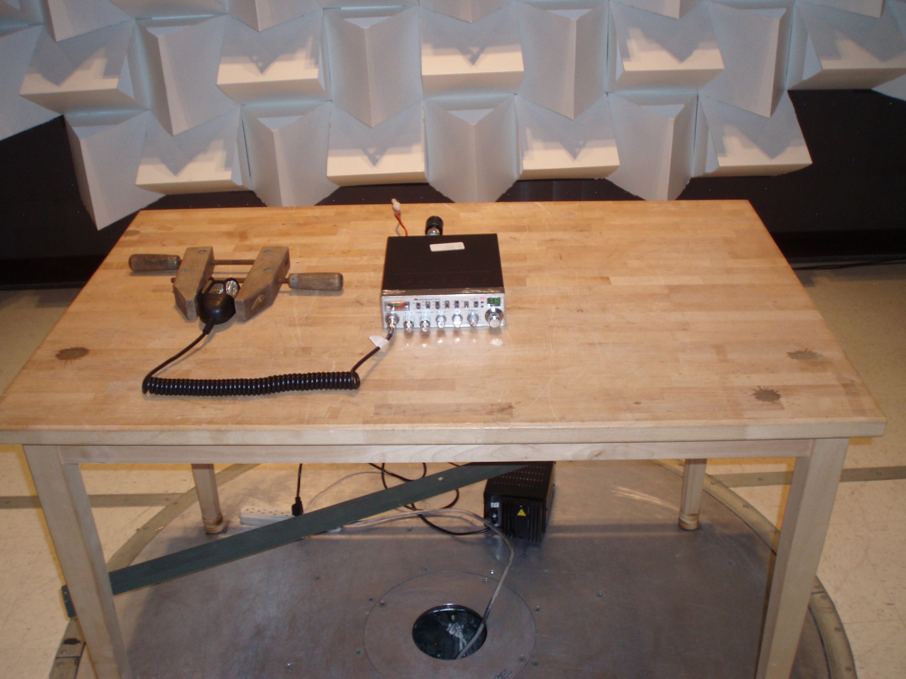
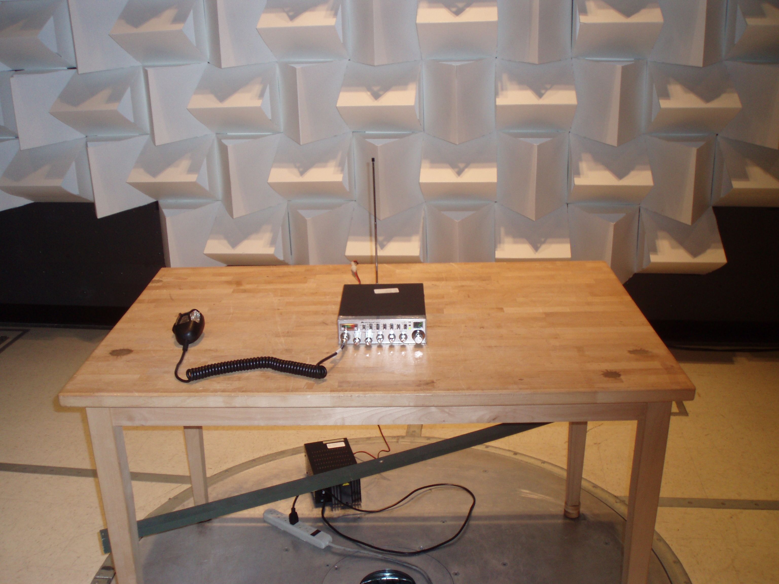
FCC PART 95 SUBPART D TEST REPORT FOR CB TRANSCEIVERS APPLICANT MIDLAND RADIO CORPORATION 5900 PARRETTA DRIVE KANSAS CITY MISSOURI 64120 USA FCC ID MMA9001Z MODEL NUMBER 9001z PRODUCT DESCRIPTION MOBILE CB TRANSCEIVER DATE SAMPLE RECEIVED 10/30/2009 DATE TESTED 11/19/2009 TESTED BY Richard Block APPROVED BY Mario de Aranzeta TIMCO REPORT NO. 2628AUT9TestReport.doc TEST RESULTS PASS FAIL THE ATTACHED REPORT SHALL NOT BE REPRODUCED EXCEPT IN FULL WITHOUT THE WRITTEN APPROVAL OF TIMCO ENGINEERING, INC. 849 NW STATE ROAD 45 NEWBERRY, FL 32669 USA PH: 888.472.2424 OR 352.472.5500 FAX: 352.472.2030 EMAIL: [email protected] HTTP://WWW.TIMCOENGR.COM Testing Certificate # 0955-01 APPLICANT: MIDLAND RADIO CORPORATION FCC ID: MMA9001Z REPORT #: M\MidlandRadio_MMA\2628AUT9\2628AUT9TestReport.doc Page 2 of 19 TABLE OF CONTENTS GENERAL REMARKS ................................................................................................... 3 GENERAL INFORMATION ............................................................................................ 4 TEST ENVIRONMENT .................................................................................................. 5 TEST SETUP SUMMARY .............................................................................................. 5 EQUIPMENT LIST ........................................................................................................ 6 TEST PROCEDURE ...................................................................................................... 7 RF POWER OUTPUT .................................................................................................... 8 MODULATION CHARACTERISTICS.............................................................................. 9 AUDIO FREQUENCY RESPONSE ................................................................................. 9 AUDIO LOW PASS FILTER RESPONSE ...................................................................... 10 AUDIO INPUT VS MODULATION ................................................................................ 11 OCCUPIED BANDWIDTH ........................................................................................... 12 SPURIOUS EMISSIONS AT ANTENNA TERMINALS (CONDUCTED)............................ 14 FIELD STRENGTH OF SPURIOUS EMISSIONS .......................................................... 16 FREQUENCY STABILITY ............................................................................................ 18 RADIATED EMISSIONS TEST SETUP PHOTO ............................................................ 19 APPLICANT: MIDLAND RADIO CORPORATION FCC ID: MMA9001Z REPORT #: M\MidlandRadio_MMA\2628AUT9\2628AUT9TestReport.doc Page 3 of 19 GENERAL REMARKS The attached report shall not be reproduced except in full without the written permission of Timco Engineering Inc. The test results relate only to the items tested. Summary The device under test does: fulfill the general approval requirements as identified in this test report not fulfill the general approval requirements as identified in this test report Attestations This equipment has been tested in accordance with the standards identified in this test report. To the best of my knowledge and belief, these tests were performed using the measurement procedures described in this report. All instrumentation and accessories used to test products for compliance to the indicated standards are calibrated regularly in accordance with ISO 17025 requirements. Testing Certificate # 0955-01 I attest that the necessary measurements were made, under my supervision, at: Timco Engineering Inc. 849 NW State Road 45 Newberry, Fl 32669 Authorized Signatory Name: Mario de Aranzeta C.E.T. Compliance Engineer/ Lab. Supervisor Date: 11/20/2009 APPLICANT: MIDLAND RADIO CORPORATION FCC ID: MMA9001Z REPORT #: M\MidlandRadio_MMA\2628AUT9\2628AUT9TestReport.doc Page 4 of 19 GENERAL INFORMATION DUT Specification DUT Description MOBILE CB TRANSCEIVER FCC ID MMA9001Z Model Number 9001Z Serial Number N/A Operating Frequency 26.965-27.405 MHz No. of Channels 40 Type of Emission 6KOOA3E Bn = 2M M = 3000 Bn = 6000 Modulation AM DUT Power Source 110–120Vac/50– 60Hz DC Power Battery Operated Exclusively Test Item Prototype Pre-Production Production Type of Equipment Fixed Mobile Portable APPLICANT: MIDLAND RADIO CORPORATION FCC ID: MMA9001Z REPORT #: M\MidlandRadio_MMA\2628AUT9\2628AUT9TestReport.doc Page 5 of 19 TEST ENVIRONMENT Test Facility Timco Engineering, Inc. 849 NW State Road 45 Newberry, FL 32669 USA. Test Condition in the laboratory Temperature: 26ºC Relative humidity: 50% TEST SETUP SUMMARY Test Setup Diagram/ Description The DUT was placed on the turntable per setup per ANSI C63.4: 2003. A test set up photo is provided for clarification. Deviation from the standard/procedure No deviation Modification of DUT No modification Applicable Standards EIA/TIA-382-A, FCC CFR 47 PART 95 APPLICANT: MIDLAND RADIO CORPORATION FCC ID: MMA9001Z REPORT #: M\MidlandRadio_MMA\2628AUT9\2628AUT9TestReport.doc Page 6 of 19 EQUIPMENT LIST Device Manufacturer Model Serial Number Cal/Char Date Due Date 3/10-Meter OATS TEI N/A N/A Listed 3/20/07 3/19/10 3-Meter OATS TEI N/A N/A Listed 2/5/09 2/5/12 3-Meter Semi- Anechoic Chamber Panashield N/A N/A Listed 5/11/07 5/10/10 Analyzer Open- Frame Tower Preamplifier HP 8449B 3008A01075 CAL 7/22/09 7/22/11 Analyzer Open- Frame Tower Quasi-Peak Adapter HP 85650A 2043A00305 CAL 7/22/09 7/22/11 Analyzer Open- Frame Tower RF Preselector HP 85685A 3107A01282 CAL 7/22/09 7/22/11 Analyzer Open- Frame Tower Spectrum Analyzer HP 8566B/8 5662A 2627A03154/26 48A14276 CAL 7/22/09 7/22/11 Antenna: Biconnical Eaton 94455-1 1057 CAL 1/15/08 1/15/10 Antenna: Biconnical Electro-Metrics BIA-25 1171 CAL 10/1/09 10/1/11 Antenna: Log- Periodic Eaton 96005 1243 CAL 12/13/07 12/13/09 LISN Electro-Metrics ANS- 25/2 2604 CAL 10/1/09 10/1/11 LISN Electro-Metrics EM-7820 2682 CAL 9/24/09 10/24/11 Signal Generator HP 8640B 2308A214…
Text truncated - open the document above for the full version.
Contact Information
Applicant
Butch Rittmann(Director of Operations)
Test Firm
Timco Engineering, Inc.Bruno Clavier
Technical Specifications
| # | Rule Parts | Frequency Range | Power Output | Emission | Tolerance |
|---|---|---|---|---|---|
| 1 | 95D | 26.965 MHz - 27.405 MHz | 4 W | 6K00A3E | 50.0000000000 ppm |
Other Applications from Midland Radio Corporation

MMAMXMC95
Jun 10, 2026Wireless Bluetooth Microphone
Equipment Class
JAB - Part 15 Class B Digital Device
MMAMXT295
Jun 08, 2026GMRS Radio
Equipment Class
TNF - Licensed Non-Broadcast Transmitter Held to Face
MMACLIPTALK
Apr 27, 2026Transceiver
Equipment Class
DTS - Digital Transmission System
MMABR200S
Jan 13, 2026BUSINESS BAND TWO-WAY RADIO
Equipment Class
TNF - Licensed Non-Broadcast Transmitter Held to Face
MMAGXT67
Oct 29, 2023GMRS RADIO
Equipment Class
TNF - Licensed Non-Broadcast Transmitter Held to Face